Kenwood KRF-V7510D Service Manual
Hide thumbs
Also See for KRF-V7510D:
- Instruction manual (24 pages) ,
- Service manual (33 pages) ,
- Instruction manual (25 pages)
Advertisement
Table of Contents
AV SURROUND RECEIVER
KRF-V7510D/VR-208
KRF-V8010D/VR-209
SERVICE MANUAL
Indicator
KENWOOD badge
(B12-0340-04)
(B43-0302-04)
AV SURROUND RECEIVER
STANDBY
ON / STANDBY
POWER
- ON
– OFF
PHONES
Knob (BUTTON)
Foot
(K27-2274-04)
(J02-1405-03)
Miniature phone jack(2P)
(E11-0347-05)
ANTENNA
AM
(ƒ)
SYSTEM CONTROL
REC OUT
GND
FM
L
75 Ω
R
PHONO
CD
Lock terminal board
Phono jack x 2
(E70-0080-05)
(E63-0172-05)
Knob
Front glass
(K29-6879-02)
(B10-2426-02)
DOLBY DIGITAL
CLIP INDICATOR
SPEAKERS
SOURCE
A
B
BASS BOOST
MONITOR
DIRECT
Phone jack(3P)
Knob
(E11-0295-05)
(K29-6879-02)
Slide switch
Phono jack
(S62-0034-05)
(E63-1020-05)
Phono jack
Phono jack
(E63-1021-05)
(E63-1022-05)
VIDEO OUT
VIDEO IN
DOLBY DIGITAL / PCM IN
SL16
MONITOR
VIDEO 1
VIDEO 1
VIDEO 2 VIDEO 3
VIDEO 2
(XS8)
PLAY IN REC OUT PLAY IN
REC OUT PLAY IN
PLAY IN
PLAY IN
CENTER
SUBWOOFER
MD / TAPE
MONITOR
VIDEO 1
VIDEO 2
VIDEO 3
PRE OUT
Phono jack x 2
(E63-0173-05)
Phono jack
(E63-1015-05)
Knob
(K29-6898-03)
DIMMER
P.CALL
P.CALL
BAND
AUTO
MEMORY
MULTI CONTROL
INPUT MODE LISTEN MODE SOUND
SETUP
Knob
(K29-6881-04)
Screw terminal board
(E70-0089-05)
R
L
C
FRONT
R
+
+
+
VIDEO 3
L
-
-
R
+
A
R
SURROUND
FRONT SPEAKERS
CENTER SPEAKER
SURROUND
Optical receiving module
(W02-1181-05)
Lock terminal board
(E70-0068-05)
© 1998-4/B51-5419-00 (K/K) 1796
Panel *
Knob
(A60-)
(K29-6880-04)
VOLUME CONTROL
INPUT SELECTOR
DOWN
UP
Foot
(J02-1405-03)
Power cord bushing
AC power cord *
(J42-0083-05)
(E30-)
SPEAKERS
L
B
-
-
+
-
-
+
L
SPEAKERS
AC outlet *
(E03-)
Metallic cabinet
(A01-3534-01)
* Refer to parts list on page 32.
Advertisement
Table of Contents

Related Manuals for Kenwood KRF-V7510D


Summary of Contents for Kenwood KRF-V7510D
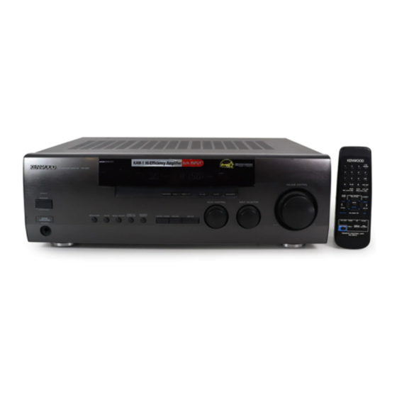
- Page 1 AV SURROUND RECEIVER KRF-V7510D/VR-208 KRF-V8010D/VR-209 SERVICE MANUAL © 1998-4/B51-5419-00 (K/K) 1796 Indicator KENWOOD badge Knob Knob Front glass Panel * Knob (B12-0340-04) (B43-0302-04) (K29-6879-02) (K29-6898-03) (B10-2426-02) (A60-) (K29-6880-04) DOLBY DIGITAL AV SURROUND RECEIVER CLIP INDICATOR VOLUME CONTROL STANDBY DIMMER P.CALL P.CALL...
-
Page 2: Table Of Contents
KRF-V7510D/V8010D/VR-208/209 CONTENTS / ACCESSORIES Contents CONTENTS / ACCESSORIES ........2 PC BOARD ..............12 CONTROLS ..............3 SCHEMATIC DIAGRAM ..........17 DISASSEMBLY FOR REPAIR........5 EXPLODED VIEW .............31 BLOCK DIAGRAM ............6 PARTS LIST...............32 CIRCUIT DESCRIPTION ..........7 SPECIFICATIONS .............41 ADJUSTMENT ............11 Accessories AM loop antenna (1) -
Page 3: Controls
KRF-V7510D/V8010D/VR-208/209 CONTROLS Frequency display, PRO LOGIC Input display, indicator Preset channel display, AUTO SOUND indicator DIGITAL indicator Surround mode display Band indicators S.DIRECT indicator AUTO indicator Speaker indicator AUTO SOUND DIGITAL AUTO MEMO. indicator * **** ** PRO LOGIC S.DIRECT MEMO. - Page 4 If you connect audio components from 2 MACRO key original remote control supplied with the KENWOOD and other makers to the MD/ Use in combination with the AUDIO, VIDEO, component you are controlling. TAPE or CD jacks, you can set the remote...
-
Page 5: Disassembly For Repair
KRF-V7510D/V8010D/VR-208/209 DISASSEMBLY FOR REPAIR (VR-257) 1. Remove the 8 screws (1,2,3), remove the rear panel. 2. Connect the GND of the rear panel and the chassis, the GND of the mounting hardware and the chassis with 2 alligators clip (4) -
Page 6: Block Diagram
(X08) TC9164AF H, P, Lch VIDEO3 STK411-230 H, P, Rch COXIAL TC9163AF DIGITAL STK407-090 SP. 5ch OUTPUT DA&AD Ω Ω VIDEO2 28.3V/8 20.0V/8 IC10 CONVERTER M62446SP OPTICAL TC9162AF (1/2) SP-A (X09) YSS248 6ch E. VOL CS4226 with IC6(1/3) TONE CONT. LS/RS IC10 TUNER... -
Page 7: Circuit Description
KRF-V7510D/V8010D/VR-208/209 CIRCUIT DESCRIPTION 1. Microprocessor CXP82832-141Q(X09 : IC51) 1-1 Microprocessor periphery block diagram Key matrix * No. of : u -COM Port NO. KS0 P.CH DOWN ON/STANDBY SPEAKER A P.CH UP DIMMER SPEAKER B FL DISPLAY (X09) ED51 BAND LISTEN MODE... - Page 8 KRF-V7510D/V8010D/VR-208/209 CIRCUIT DESCRIPTION 1-2 Pin description Pin No. Pin Name Description G10,11 Display grids 10,11 None – Ic test mode port. None No connect AUDIO Audio signal detection port. L=AUDIO. VOL.ENC.A Volume encoder A(clockwise) output. REMOCON Remote contol signal input.
- Page 9 KRF-V7510D/V8010D/VR-208/209 CIRCUIT DESCRIPTION Pin No. Pin Name Description FB.RLY Front B speaker relay control. H=relay on. C.RLY Center speaker relay control. H=relay on. S.RLY Rear speaker relay control. H=relay on. POWER.RLY Power relay control. H=relay on. STANDBY.LED Standby led control.L=led on.
- Page 10 KRF-V7510D/V8010D/VR-208/209 CIRCUIT DESCRIPTION Pin No. Pin Name Descriptions Microprocessor interface serial data output port. Microprocessor interface serial data input port. Microprocessor interface clock input port. TEST Test port. – Power supply(+5V) 72~79 STREAM STREAM detection port. – – Power supply(+5V) SDIWCK Word clock for SD input ports.
-
Page 11: Adjustment
KRF-V7510D/V8010D/VR-208/209 ADJUSTMENT INPUT OUTPUT RECEIVER ALIGNMENT ALIGN ITEM FIG. SETTINGS SETTINGS SETTINGS POINTS FM SECTION SELECTOR : FM 98.0MHz Minimum 1kHz,±68.25kHz dev. DISTORTION 98.0 MHz distortion Selector : L or R (TUNER A1) (STEREO) (L or R) Pilot : ±6.75kHz dev. -
Page 12: Pc Board
PC BOARD (Component side view) POWER SUPPLY UNIT AC OUTLET SYSTEM CONTROL X00-287X-XX (J70-1173-11) CENTER FRONT SPEAKER SPEAKERS X00 B/6 X00 D/6 POWER PHONES AC220- AC110- AC220- AC110- 240V 120V 240V 120V Refer to the schematic diagram for the value of resistors and capacitors. - Page 13 PC BOARD (Component side view) TUNER UNIT SURROUND UNIT X05-482X-XX X08-284X-XX ANTENNA (J70-1145-11) (J70-1169-21) SYSTEM CONTROL MONITOR VIDEO1 1 14 VIDEO1 VIDEO2 VIDEO3 VIDEO2 VIDEO3 Refer to the schematic diagram for the value of resistors and capacitors.
- Page 14 PC BOARD (Component side view) AUDIO UNIT FRONT CENTER SPEAKER SPEAKERS A FRONT SPEAKERS B PRE OUT SURROUND SPEAKERS VIDEO 1 MONITOR MD/TAPE PLAY PLAY PLAY PLAY PLAY PHONO X09-489X-XX A/3 (J70-1171-21) X09 C/3 X09 B/3 Refer to the schematic diagram for the value of resistors and capacitors.
- Page 15 L72-0596 YES 2.2K 330P 390P 0.033 2.2u50 0.022 W02-2622 DETECTOR CANADA RD2.7ES(B2) or RESET MTZJ2.7(B) 10.3V 1.2K KRF-V7510D (X05-4820-21) D7,8,13,16 MA111 DESTINATION R72, C30, RD3.3ES(B2) or UNIT No. CF1,2 D , E DATA SHIFT REGISTER LATCH UNIVERSAL COUNTER 470P COUNTRY ABB.
- Page 16 SURROUND UNIT (X08-2840-10) SRch C132 R134 DIGITAL 4.7u50 5.1K IC24 SLch C131 R133 4.7u50 5.1K R36 1K SERIAL AUDIO DATA INTERFACE R9 220 3.4V R8 220 +15V 1000P 1000P DIGITAL DIGITAL FILTERS C152 R154 FILTERS 4.7u50 5.1K 330P 2.9V 2.8V DAC,A/D 4.3V CONVERTER...
-
Page 17: Schematic Diagram
12 VIDEO1 R208 R209 SWch X00- TRNS 3 VIDEO2 1 VIDEO3 IC23 IC22 (1/2) (1/2) SW MIX SWch 90Hz L.P.F. -14.8V -14.8V -15V -15V -15V -15V X09-B/3 +15V +15V +15V -CN52 ANA Rch ANA Lch VR208/209(K) (2/4) KRF-V5551D/V7510D/V8010D(M) (2/4) KRF-V7510D/V8010D/VR-208/209 Y05-3600-10... - Page 18 (X09-XXXX-XX) (A/3) +15V VR-208 (X09-4890-11) 15.0V PHONO EQ AMP DESTINATION (AUDIO) C21,22, C23-26, C33,34, D1,11-14, R1,2, R3,4,16, R27,28, R229, R241, R315,316, R343, R367, R369- W4,10,12,28,57,58,60, W56,63, C103 UNIT No. C1,2 C5,6 C7,8 (1/2) COUNTRY ABB. 29,30 31,32 39,40 22,25,26 242,253 329,330,363 347,358 129,130,219,220...
- Page 19 KRF-V7510D (X09-4892-91) DESTINATION C7,8 C21,22, C23-26, C33,34, D1,11-14, R1,2, R3,4,16, R27,28, R229, R241, R315,316, R343, R367, R369- W4,10,12,28,57,58,60, W56,63, UNIT No. C1,2 C5,6 29,30 31,32 39,40 22,25,26 242,253 329,330,363 347,358 129,130,219,220 79,128 COUNTRY ABB. R343 2-91 3300u50 47u50 3900P50 MA111...
- Page 20 2SC4116 2 SWch 2SC2003 PRE OUT 2SC2631 CN11 3 SLch 2SC2878 2SC3940A COLD 4 SRch USED EXCEPT (M,Y) TYPE KRF-V7510D (Y) 1 Rch POWER TRANSFORMER 2SD1757K 2SA1535 TC74HCU04AF FRONT A SP. (X00-287X-XX) (A/6) USED EXCEPT 2 Lch (K,P) TYPE (X00- ) (B/6) 3 Cch CENTER SP.
- Page 21 (BOTTOM VIEW) PROTECTION U.S.A. STANDBY R544 100K 0-11 NO YES 4.5V S DATA CANADA D502 POWER DOLBY DIGITAL S BUSY KRF-V7510D (X09-4892-91) RELAY R R555 10K 4.8V 4.4V E2 DATA DESTINATION D504, C534, RELAY C S518 UNIT No. D505 IC52...
- Page 22 220-240V~ AC110- AC220- 120V~ 1240V~ AC110- AC220- X00-2870-21 120V~ 1240V~ (A/6) M4x6 : N09-1966-05 (VR-209/KRF-V8010D) M4x6 : N86-4006-46 (VR-208/KRF-V7510D) (15P) : N09-3411-05 (C/6) X08-2840-10 : N29-0216-05 : N82-2608-46 ø3x6 : N89-3006-45 ø3x8 : N89-3008-45 ø3x8 : N89-3008-46 SYSTEM VIDEO VIDEO2...
- Page 23 Parts No. Description Ref. No Parts No. Description ress Parts nation marks ress Parts nation marks VR-208/209/KRF-V7510D/V8010D H10-7418-02 POLYSTYRENE FOAMED FIXTURE L H10-7419-02 POLYSTYRENE FOAMED FIXTURE R A01-3534-01 METALLIC CABINET H25-0232-04 PROTECTION BAG (235X350X0.03) A09-0366-08 BATTERY COVER H25-0391-04 PROTECTION BAG...
- Page 24 New Parts New Parts Parts without Parts No. are not supplied. Parts without Parts No. are not supplied. Les articles non mentionnes dans le Parts No. ne sont pas fournis. Les articles non mentionnes dans le Parts No. ne sont pas fournis. Teile ohne Parts No.
- Page 25 New Parts New Parts Parts without Parts No. are not supplied. Parts without Parts No. are not supplied. Les articles non mentionnes dans le Parts No. ne sont pas fournis. Les articles non mentionnes dans le Parts No. ne sont pas fournis. Teile ohne Parts No.
- Page 26 New Parts New Parts Parts without Parts No. are not supplied. Parts without Parts No. are not supplied. Les articles non mentionnes dans le Parts No. ne sont pas fournis. Les articles non mentionnes dans le Parts No. ne sont pas fournis. Teile ohne Parts No.
- Page 27 New Parts New Parts Parts without Parts No. are not supplied. Parts without Parts No. are not supplied. Les articles non mentionnes dans le Parts No. ne sont pas fournis. Les articles non mentionnes dans le Parts No. ne sont pas fournis. Teile ohne Parts No.
- Page 28 New Parts New Parts Parts without Parts No. are not supplied. Parts without Parts No. are not supplied. Les articles non mentionnes dans le Parts No. ne sont pas fournis. Les articles non mentionnes dans le Parts No. ne sont pas fournis. Teile ohne Parts No.
- Page 29 New Parts New Parts Parts without Parts No. are not supplied. Parts without Parts No. are not supplied. Les articles non mentionnes dans le Parts No. ne sont pas fournis. Les articles non mentionnes dans le Parts No. ne sont pas fournis. Teile ohne Parts No.
- Page 30 New Parts New Parts Parts without Parts No. are not supplied. Parts without Parts No. are not supplied. Les articles non mentionnes dans le Parts No. ne sont pas fournis. Les articles non mentionnes dans le Parts No. ne sont pas fournis. Teile ohne Parts No.
-
Page 31: Exploded View
– – – – NJM4580ED ANALOGUE IC TC9164AF MOS-IC VR-209 – – – – – – – – TC9163AF MOS-IC KRF-V7510D – – – – – – – – – KRF-V8010D – – – – – – – – –... -
Page 32: Parts List
Input level / impedance / wave length Optical ....... -15 dBm ~ -21 dBm, 600 nm ±30nm Coaxial ..............0.5 Vp-p / 75 Ω 1. KENWOOD follows a policy of continuous advancements in development. For this reason specifications may be changed without notic e. Notes Notes... - Page 33 Unit 3712-3724, Level 37, Tower 1, Metroplaza, 223 Hing Fong Road, Kwai Fong N.T., Hong Kong KENWOOD ELECTRONICS U.K. LIMITED KENWOOD ELECTRONICS GULF FZE KENWOOD House, Dwight Road, Watford, Herts., WD1 8EB., United Kingdom P.O.Box 61318, Jebel Ali, Dubai, U.A.E. KENWOOD ELECTRONICS BELGUM N.V.