
Related Manuals for Sony XR-C5080R


Summary of Contents for Sony XR-C5080R
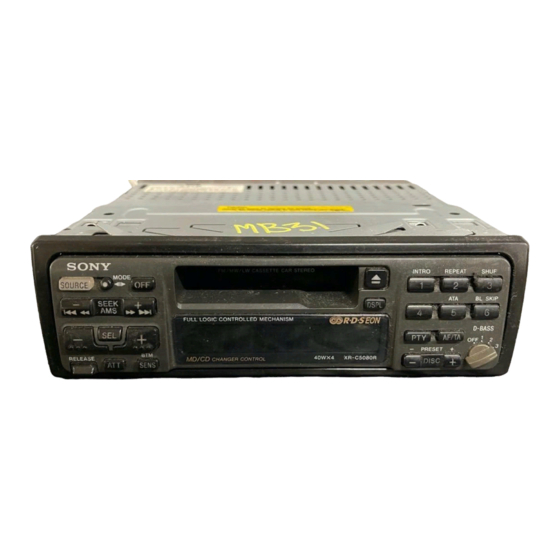
- Page 1 XR-C5080R/C5090R SERVICE MANUAL AEP Model UK Model Photo: XR-C5090R Model Name Using Similar Mechanism XR-5800R Tape Transport Mechanism Type MG-25G-136 SPECIFICATIONS FM/MW/LW CASSETTE CAR STEREO MICROFILM...
- Page 2 TABLE OF CONTENTS Flexible Circuit Board Repairing • Keep the temperature of the soldering iron around 270 ˚C dur- ing repairing. GENERAL • Do not touch the soldering iron on the same conductor of the Location of Controls ............3 circuit board (within 3 times).
- Page 3 SECTION 1 This section is extracted from instruction manual. GENERAL – 3 –...
- Page 4 – 4 –...
- Page 5 – 5 –...
- Page 6 – 6 –...
- Page 7 – 7 –...
- Page 8 – 8 –...
- Page 9 SECTION 2 DISASSEMBLY Note: Follow the disassembly procedure in the numerical order given. FRONT PANEL ASS’Y 1 Push the button (release). 2 Remove the front panel ass’y to the direction of the arrow A . COVER ASS’Y 3 cover ass’y –...
- Page 10 SUB PANEL, MECHANISM DECK (MG-25G-136) 5 screw (PTT2.6 × 6) 3 connector (CN352) 6 mechanism deck (MG-25G-136) 4 flexible flat cable (CN351) 2 sub panel 1 three screws (PTT2.6 × 8) 1 three screws (PTT2.6 × 8) MAIN BOARD, HEAT SINK 5 two screws 6 three screws (PTT2.6 ×...
-
Page 11: Assembly Of Mechanism Deck
SECTION 3 ASSEMBLY OF MECHANISM DECK Note: Follow the assembly procedure in the numerical order given. 7 Holder the hanger by bending the claw. 5 Fit projection on C part. HOUSING 1 Install the catch to the hanger. 2 Install the hanger onto two claws of the housing. - Page 12 LEVER (LDG-A) / (LDG-B) shaft A shaft A shaft B shaft B shaft C 1 Fit the lever (LDG-A) on shafts A – C and install it. 3 type-E stop ring 2.0 2 Fit the lever (LDG-B) on shafts A and B and install it.
- Page 13 GUIDE (C) 2 guide (C) 1 three claws – 13 –...
-
Page 14: Mechanical Adjustments
SECTION 5 SECTION 4 ELECTRICAL ADJUSTMENTS MECHANICAL ADJUSTMENTS 1. Clean the following parts with a denatured-alcohol-moistened TEST MODE swab: This set have the test mode function. In the test mode, FM Auto playback head pinch roller Scan/Stop Level and AM (MW) Auto Scan/Stop Level adjustments rubber belt capstan can be performed easier than it in ordinary procedure. - Page 15 FM Noise Focus Adjustment TUNER SECTION 0 dB=1µV Setting: [SOURCE] button: FM Cautions during repair When the tuner unit is defective, replace it by a new one be- FM RF signal level meter cause its internal block is difficult to repair. antenna jack (J1) generator 0.01 µ...
- Page 16 FM Signal Meter Adjustment AM (MW) Auto Scan/Stop Level Adjustment Setting: Make this adjustment after “FM Auto Scan/Stop Level Adjust- [SOURCE] ment”. button: FM Setting: FM RF signal [SOURCE] button: MW generator antenna jack (J1) 30 Ω 15 pF 0.01 µ F 65 pF Carrier frequency : 98.00 MHz : 35 dB (56.2 µ...
- Page 17 Adjustment Location: – SET UPPER VIEW – Tape Speed Adjustment RV1 AM (MW) Auto Scan/Stop Level Adjustment RV2 FM Auto Scan/Stop Level Adjustment RV3 FM Noise Focus Adjustment RV4 FM Stereo Separation Adjustment RV1 FM Signal Meter Adjustment – 17 –...
- Page 21 • IC Block Diagrams – MAIN Section – IC1 TB2114F (EL) 24 23 21 20 14 13 RIPPLE FILTER – – SEEK/RECP SEEK/RECP 4BIT SWALLOW MODULAS COUNTER PRESCALER 12BIT PHASE PROGRAMABLE COMPARATOR COUNTER REFERENCE 40BIT 18BIT 20BIT COUNTER 22BIT SHIFT IF COUNTER 18BIT RESISTER...
- Page 22 IC151 LC75373ED – LFIN – – – LFOUT – LSELO LROUT – – – VREF SHIFT DECODER LATCH CONTROL REGISTER – – – RROUT RSELO – RFOUT – – – – RFIN 6 7 8 9 10 IC351 CXA2509AQ-T4 IC360 MM1322XFBE 8 OUT2 24dB 120µ/70µ...
- Page 23 IC601 BA3918-V2 IC701 BA8270F-E2 BUS ON BUS ON SWITCH REGULATOR RESET SWITCH BUS ON CLK IN BATTERY BATT BU IN SWITCH OVER VOLTAGE PROTECT VREF DATA DATA IN – DATA OUT 2 3 4 • Waveforms – MAIN Section – 2 IC3 9 XO 1 IC1 1 XO 42 mVp-p...
- Page 24 6-5. IC PIN FUNCTION DESCRIPTION • MAIN BOARD IC501 MN1886426SA (SYSTEM CONTROLLER) Pin No. Pin Name Function TUNMUT FM audio signal muting control output terminal “H”: muting on AMPON Standby control signal output to the power amplifier (IC801) “L”: standby Power supply on/off control signal output terminal at the illumination and liquid crystal display driver (IC901) “H”: power on ILLON...
- Page 25 Ground terminal (for A/D converter) — Ground terminal BUSON Bus on/off control signal output to the bus interface (IC701) (for SONY bus) “L”: bus on SYSRST Reset signal output to the bus interface (IC701) (for SONY bus) “L”: reset SEKOUT...
- Page 26 Pin No. Pin Name Function Input of FM stereo detection signal from FM/AM tuner unit (TU1), and output of forced monaural control signal to FM/AM tuner unit (TU1) (Commonly used for stereo display input ST IN and forced monaural output) FM stereo detection at input of “L”, forced monaural at output of “L”...
-
Page 27: Exploded Views
A-3313-456-A POWER BOARD, COMPLETE (XR-C5090R: German) 1-782-092-11 CORD (WITH CONNECTOR) (ISO-P) (POWER) A-3313-481-A MAIN BOARD, COMPLETE 1-782-093-11 CORD (WITH CONNECTOR) (ISO-S) (SPEAKER) (XR-C5080R: AEP, UK) A-3313-482-A MAIN BOARD, COMPLETE 1-777-989-21 CORD (WITH CONNECTOR) (AMP REM) (XR-C5080R: German) * 19 3-019-148-01 BRACKET (HS) (M) - Page 28 3-010-395-01 SPRING (RELEASE) * 63 3-018-386-01 HOLDER (LCD) X-3374-693-1 PANEL SUB ASSY (XR-C5090R) 3-010-382-01 PANEL, FRONT BACK X-3374-694-1 PANEL SUB ASSY (XR-C5080R) 3-015-036-01 CUSHION (BACK PANEL) 3-010-383-01 BUTTON (SOURCE) * 66 3-014-861-01 SHEET (LCD) (B) 3-010-384-01 BUTTON (M. O. S) LCD901 1-801-968-11 DISPLAY PANEL, LIQUID CRYSTAL (r.
- Page 29 (3) MECHANISM DECK SECTION (MG-25G-136) HP901 M901 Ref. No. Part No. Description Remark Ref. No. Part No. Description Remark A-3291-667-A CLUTCH (FR) ASSY 3-933-346-01 CATCHER * 152 3-019-130-01 LEVER (LDG-A) 3-933-344-01 GUIDE (C) * 153 3-019-131-01 LEVER (LDG-B) 3-014-798-01 SCREW (HEAD), SPECIAL 3-020-539-01 SPRING (LD-1), TENSION 3-364-151-01 WASHER 3-020-540-01 SPRING (LD-2), TENSION...
-
Page 30: Electrical Parts List
(MODE/*) (XR-C5090R) 3-018-385-01 PLATE (LCD), LIGHT GUIDE LSW904 1-762-617-11 SWITCH, KEY BOARD (WITH LED) 3-018-386-01 HOLDER (LCD) (SEEK/AMS, + ) + ) (XR-C5080R) LSW904 1-762-620-11 SWITCH, KEY BOARD (WITH LED) < CAPACITOR > (SEEK/AMS, + ) + ) (XR-C5090R) LSW905 1-762-617-11 SWITCH, KEY BOARD (WITH LED) - Page 31 (PRESET +/DISC +) (XR-C5090R) (XR-C5090R) R963 1-216-037-00 METAL CHIP 1/10W LSW931 1-762-617-11 SWITCH, KEY BOARD (WITH LED) (− PRESET/ − DISC) (XR-C5080R) R964 1-216-033-00 METAL CHIP 1/10W LSW931 1-762-620-11 SWITCH, KEY BOARD (WITH LED) (XR-C5090R) (− PRESET/ − DISC) (XR-C5090R)
- Page 32 MAIN Ref. No. Part No. Description Remark Ref. No. Part No. Description Remark 3-018-613-01 HEAT SINK C157 1-124-584-00 ELECT 100uF 3-018-798-01 BRACKET (IC) C158 1-163-031-11 CERAMIC CHIP 0.01uF 3-019-148-01 BRACKET (HS) (M) C201 1-163-037-11 CERAMIC CHIP 0.022uF 7-685-794-09 SCREW +PTT 2.6X10 (S) C202 1-126-160-11 ELECT 7-685-796-09 SCREW +PTT 2.6X14 (S)
- Page 33 MAIN Ref. No. Part No. Description Remark Ref. No. Part No. Description Remark C606 1-126-157-11 ELECT 10uF D623 8-719-970-02 DIODE 1SR139-400 C607 1-126-157-11 ELECT 10uF D624 8-719-404-49 DIODE MA111 C609 1-124-589-11 ELECT 47uF D651 8-719-018-04 DIODE MA8240-TX C610 1-124-234-00 ELECT 22uF D652 8-719-018-04 DIODE MA8240-TX...
- Page 34 MAIN Ref. No. Part No. Description Remark Ref. No. Part No. Description Remark JC51 1-216-296-00 SHORT (CHIP) 0 JC52 1-216-296-00 SHORT (CHIP) 0 < RESISTOR > JC53 1-216-296-00 SHORT (CHIP) 0 JC54 1-216-296-00 SHORT (CHIP) 0 1-216-049-11 RES, CHIP 1/10W JC55 1-216-296-00 SHORT (CHIP) 0 1-216-065-00 METAL CHIP...
-
Page 35: Main Power
1/8W S601 1-692-431-21 SWITCH, TACTILE (RESET) R534 1-216-246-00 RES, CHIP 100K 1/8W R535 1-208-814-11 RES, CHIP 1/10W < TUNER UNIT > (XR-C5080R) R535 1-216-097-00 RES, CHIP 100K 1/10W 1-693-373-11 TUNER UNIT (FM/AM) (XR-C5090R) R536 1-216-246-00 RES, CHIP 100K 1/8W < VIBRATOR >... - Page 36 (GERMAN, FRENCH, DUTCH, ITALIAN) (XR-C5090R: AEP, German) < SHORT > 3-861-725-11 MANUAL, INSTRUCTION (ENGLISH, SPANISH, SWEDISH, PORTUGUESE) JC801 1-216-296-00 SHORT (CHIP) 0 (XR-C5080R: AEP, UK) JC802 1-216-296-00 SHORT (CHIP) 0 3-861-725-21 MANUAL, INSTRUCTION JC803 1-216-295-00 SHORT (CHIP) 0 (GERMAN, FRENCH, DUTCH, ITALIAN) (XR-C5080R: AEP) <...
- Page 37 Ref. No. Part No. Description Remark PARTS FOR INSTALLATION AND CONNECTIONS *************************************** 3-916-161-31 FRAME ASSY X-3370-077-1 SCREW ASSY (AE. KEY), FITTING 1-775-543-11 CORD, GROUND 1-782-092-11 CORD (WITH CONNECTOR) (ISO-P) (POWER) 1-782-093-11 CORD (WITH CONNECTOR) (ISO-S) (SPEAKER) 1-465-459-21 ADAPTER, ANTENNA 1-777-989-21 CORD (WITH CONNECTOR) (AMP REM) X-3373-432-1 BRACKET ASSY (for RM-X4S) (XR-C5090R) –...
- Page 38 XR-C5080R/C5090R Sony Corporation 98A057542-1 9-925-694-11 Personal & Mobile Communication Company Printed in Hungary © 1998. 1 – 48 – Published by Quality Assurance Dept.