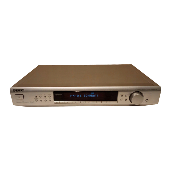
Sony ST-SE520 Service Manual
Stereo
Hide thumbs
Also See for ST-SE520:
- Operating instructions manual (72 pages) ,
- Operating instructions manual (44 pages)

Related Manuals for Sony ST-SE520


Summary of Contents for Sony ST-SE520
- Page 1 7/23/2017 ST-SE520 SERVICE MANUAL AEP Model UK Model SPECIFICATIONS FM STEREO FM-AM TUNER Digitized in Heiloo Netherland...
-
Page 2: Table Of Contents
REPLACE THESE COMPONENTS WITH SONY PARTS 3. ELECTRICAL ADJUSTMENTS ......... 5 WHOSE PART NUMBERS APPEAR AS SHOWN IN THIS MANUAL OR IN SUPPLEMENTS PUBLISHED BY SONY. 4. DIAGRAMS 4-1. Circuit Boards Location ............5 4-2. Schematic Diagram – Tuner Section – ......... 6 4-3. -
Page 3: Test Mode
www.freeservicemanuals.info 7/23/2017 SECTION 2 TEST MODE 1. Circuit Check Mode Set to the reception frequency that the circuit can STEREO RDS stations. (Set the input level to above 70 dB.) This enables circuit check to be performed in any of the reception modes-FM, AM (MW, LW). Set to a desired band before setting the test mode. - Page 4 www.freeservicemanuals.info 7/23/2017 NOTE : The preset data will be erased when this test mode is used. Therefore, take down the data before setting this mode and preset the data again after completing operations in this mode. 2. Display Tube Check and KEY Check mode 1.
-
Page 5: Electrical Adjustments
www.freeservicemanuals.info 7/23/2017 SECTION 3 SECTION 4 ELECTRICAL ADJUSTMENTS DIAGRAMS FM Signal Level Adjustment Adjustment Location: 4-1. CIRCUIT BOARDS LOCATION FM RF signal [TUNER BOARD] — Component Side — generator TRANSFORMER board IC201 TUNER board AC SW board Carrier frequency : 98 MHz RV201 Modulation : 1 kHz, 40 kHz deviation... -
Page 6: Schematic Diagram - Tuner Section
7/23/2017 ST-SE520 4-2. SCHEMATIC DIAGRAM – TUNER SECTION – • See page 5 for Waveform. • See page 11 for IC Block Diagram. (Page 8) (Page 8) Digitized in Heiloo Netherland... -
Page 7: Printed Wiring Board -Tuner Section
7/23/2017 ST-SE520 4-3. PRINTED WIRING BOARD –TUNER SECTION – • See page 5 for Circuit Boards Location. (Page 9) (Page 9) • Semiconductor Location Ref. No. Location Ref. No. Location D201 IC201 D901 IC302 IC802 D902 D903 IC901 D904... -
Page 8: Schematic Diagram - Display Section
7/23/2017 ST-SE520 4-4. SCHEMATIC DIAGRAM – DISPLAY SECTION – • See page 5 for Waveform. • See page 10 for IC Pin function. (Page 6) (Page 6) FUNCTION Digitized in Heiloo Netherland... -
Page 9: Printed Wiring Board - Display Section
7/23/2017 ST-SE520 4-5. PRINTED WIRING BOARD – DISPLAY SECTION – • See page 5 for Circuit Boards Location. (Page 7) (Page 7) Digitized in Heiloo Netherland... -
Page 10: Ic Pin Function
www.freeservicemanuals.info 7/23/2017 4-6. IC PIN FUNCTION • IC701 System Control (µPD78205GF-040-3BA) Pin Name Function Pin No. Pin Name Function — Power supply (+5V) IS 5 — Not used IS 4 — Not used IS 3 Model detection BAND 1 — Not used IS 2 BAND 2... -
Page 11: Ic Block Diagrams
www.freeservicemanuals.info 7/23/2017 4-7. IC BLOCK DIAGRAMS • Tuner section IC201 LA1235 IC901 LA5667 MUTING CIRCUIT CONTROL DETUNE LEVEL METER DRIVE IF OFF NULL METER SHORTING FM IF AMP QUADRATURE AF/NULL LIMITER METER AF AMP IC802 BU1922 TEST LOGIC AND OUTPUT SELECTOR SWITCH 57kHz OSCILLATOR... -
Page 12: Exploded View
3-703-685-21 SCREW (+BV 3X8) 4-981-264-21 BUTTON (4)(SILVER) 3-704-515-31 SCREW (BV/RING) 4-997-881-01 ESCUTCHEON (BLACK) 7-685-646-79 SCREW +BVTP 3X8 TYPE2 IT-3 4-997-881-11 ESCUTCHEON (SILVER) 4-963-404-21 EMBLEM (5-A), SONY 1-668-815-11 ENCODER BOARD 1-773-002-11 WIRE (FLAT TYPE)(15 CORE) * 10 A-4407-375-A DISPLAY BOARD, COMPLETE * 26... -
Page 13: Electrical Parts List
www.freeservicemanuals.info 7/23/2017 SECTION 6 AC SW DISPLAY ELECTRICAL PARTS LIST Note: • Due to standardization, replacements in the parts list • SEMICONDUCTORS The components identified by may be different from the parts specified in the In each case, u: µ , for example: mark 0 or dotted line with mark uA...: µ... - Page 14 www.freeservicemanuals.info 7/23/2017 ENCODER DISPLAY TRANSFORMER TUNER Ref. No. Part No. Description Remark Ref. No. Part No. Description Remark R747 1-249-413-11 CARBON 1/4W F < CONNECTOR > R749 1-249-413-11 CARBON 1/4W F R750 1-249-413-11 CARBON 1/4W F CNP901 1-580-230-11 PIN, CONNECTOR (PC BOARD) 2P CNP951 1-564-321-00 PIN, CONNECTOR 2P R751 1-249-413-11 CARBON...
- Page 15 www.freeservicemanuals.info 7/23/2017 TUNER Ref. No. Part No. Description Remark Ref. No. Part No. Description Remark C909 1-126-967-11 ELECT 47uF R310 1-247-815-91 CARBON 1/4W 0 R316 C910 1-126-964-11 ELECT 10uF 1-249-405-11 CARBON 1/4W F C911 1-126-959-11 ELECT 0.47uF R317 1-249-417-11 CARBON 1/4W F R318 1-249-417-11 CARBON...
- Page 16 7/23/2017 ST-SE520 Sony Corporation 9-922-832-12 2000D097511-1 Home Audio Division Company Printed in Hungary © 2000. 4 Digitized in Heiloo Netherland Published by Quality Assurance Dept.