Fujitsu ARYG18LLTB Installation Manual
Indoor unit duct type
Hide thumbs
Also See for ARYG18LLTB:
- Design & technical manual (425 pages) ,
- Service manual (114 pages) ,
- Service manual (23 pages)
Table of Contents
Advertisement
AIR CONDITIONER
INSTALLATION MANUAL
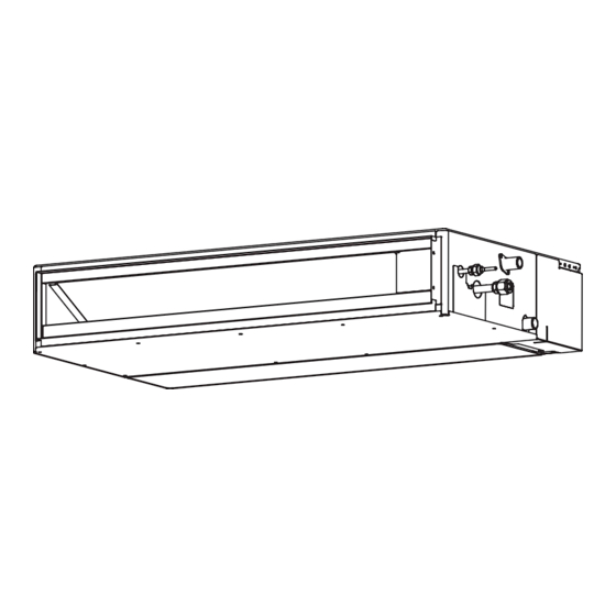
INDOOR UNIT (Duct Type)
For authorized service personnel only.
INSTALLATIONSANLEITUNG
INNENGERÄT (Für Luftkanalsysteme)
Nur für autorisiertes Fachpersonal.
MANUEL D'INSTALLATION
APPAREIL INTÉRIEURE (Type conduit)
Pour le personnel agréé uniquement.
MANUAL DE INSTALACIÓN
UNIDAD INTERIOR (Con conductos)
Sólo para personal de servicio autorizado.
MANUALE DI INSTALLAZIONE
UNITÀ INTERNA (Tipo di condotto)
Ad uso esclusivo del personale tecnico autorizzato.
ΕΓΧΕΙΡΙΔΙΟ ΕΓΚΑΤΑΣΤΑΣΗΣ
ΕΣΩΤΕΡΙΚΗ ΜΟΝΑΔΑ (Τύπος αγωγού)
Μόνο για εξουσιοδοτημένο τεχνικό προσωπικό.
MANUAL DE INSTALAÇÃO
UNIDADE INTERIOR (Tipo conduta)
Apenas para pessoal de assistência autorizado.
РУКОВОДСТВО ПО УСТАНОВКЕ
ВНУТРЕННИЙ МОДУЛЬ (Канального типа)
Только для авторизованного обслуживающего персонала.
MONTAJ KILAVUZU
İÇ ÜNİTE (Oluk tipi)
Yalnızca yetkili servis personeli için.
PART NO. 9374342235-02
AMP Air Conditioning
www.ampair.co.uk | sales@ampair.co.uk
Advertisement
Table of Contents

Related Manuals for Fujitsu ARYG18LLTB


Summary of Contents for Fujitsu ARYG18LLTB
-
Page 1: Air Conditioner
AIR CONDITIONER INSTALLATION MANUAL INDOOR UNIT (Duct Type) For authorized service personnel only. INSTALLATIONSANLEITUNG INNENGERÄT (Für Luftkanalsysteme) Nur für autorisiertes Fachpersonal. MANUEL D'INSTALLATION APPAREIL INTÉRIEURE (Type conduit) Pour le personnel agréé uniquement. MANUAL DE INSTALACIÓN UNIDAD INTERIOR (Con conductos) Sólo para personal de servicio autorizado. MANUALE DI INSTALLAZIONE UNITÀ... -
Page 2: Table Of Contents
Contents CAUTION PART NO. 9374342235-02 Read carefully all security information before use or install the air conditioner. INDOOR UNIT (Duct Type) Do not attempt to install the air conditioner or a part of the air conditioner by yourself. SAFETY PRECAUTIONS ..................2 ABOUT THE UNIT .....................2 This unit must be installed by qualified personnel with a capacity certificate for handling refrigerant fluids. -
Page 3: Accessories
2.3. Accessories Name and Shape Q’ty Application Hose band For installing drain hose WARNING For installation purposes, be sure to use the parts supplied by the manufacturer or other prescribed parts. The use of non-prescribed parts can cause serious accidents such as the unit to fall, water leakage, electric shock, or fi... -
Page 4: Installation Dimensions (Ceiling Concealed Type)
CAUTION 3.2B. Installation dimensions (Wall mounted type/Floor standing concealed type) If children under 10 years old may approach the unit, take preventive measures so that they cannot reach the unit. The wall mounted type/fl oor standing concealed type requires a temperature correction •... - Page 5 Replace the cover as follows. Inlet side • Remove the screws, and then remove cover and fan guard. • Install the cover with the screws as shown in the illustration below. Model Screw 7000, 9000, 12000, 14000 Btu/h 18000 Btu/h Screw Cover 7000, 9000, 12000, 14000 Btu/h...
-
Page 6: Install The Unit (Wall Mounted Type/Floor Standing Concealed Type)
3.3A.4. FIX THE UNIT 3.3B. Install the unit (Wall mounted type/Floor standing (1) Hang the unit concealed type) Hanger Hanger bolt WARNING Install the air conditioner in a location which can withstand a load do at least 5 times the Nut A weight of the main unit and which will not amplify sound or vibration. -
Page 7: Pipe Installation
3.3B.2. INSTALL THE FILTER • Install the fi lters (Accessories) to the unit. PROHIBITED CAUTION Filter (Accessories) Fasten the unit securely with Special nuts A and B. 4. PIPE INSTALLATION CAUTION Be careful that foreign matter (oil, water, etc.) does not enter the piping with refrigerant Unit Filter R410A models. -
Page 8: Flare Connection (Pipe Connection)
When the fl are nut is tightened properly by your hand, hold the body side coupling with 4.3. Flare connection (Pipe connection) a separate spanner, then tighten with a torque wrench. (See the table below for the fl are nut tightening torques.) WARNING Tighten with 2 wrenches. -
Page 9: When Drain Pump Is Not Used (Natural Drainage)
Gap of 1.5 to 2 m (1) Ceiling concealed type Gap of 1.5 to 2 m Supporter Locally arranged pipe Downward gradient 2.5-5.0 mm VP25 [O.D Max. 300 mm Supporter 32 mm or more] 100 mm or more 700 mm or less VP25 [O.D 32 mm Locally arranged pipe Horizontal or... -
Page 10: Install The Drain Pipe
• STEP1~STEP3 5.2. Install the drain pipe Butt the insulation against the unit. (1) Be sure to use supplied Drain hose 1 and Hose band 2 Unit 2 Hose band 1 Drain hose Slit Hard PVC side Drain hole Hose band STEP 1 Press fi... -
Page 11: Electrical Wiring
Note: Check for drainage When handling PCB, static electricity charged in the body may cause malfunction of Pour about 1 liter of water from the position shown in the diagram or from the airfl ow the PCB. Follow the cautions below: outlet to the dew tray. - Page 12 Connection diagrams Simultaneous twin (18, 22, 24 type only) Connection cable J u n c t i o n b o x Standard pair (Local purchase) Indoor unit (Primary) Outdoor unit Earth (Ground) line Connection cable Outdoor unit Indoor unit Earth (Ground) line Power line Earth (Ground) line...
-
Page 13: Connection Cable Preparation
CAUTION Tighten the indoor unit connection cable and power supply indoor and outdoor unit, branch box terminal board connections fi rmly with the terminal board screws. Faulty connection may cause a fi re. Remote controller cable If the indoor unit connection cable and power supply are wired incorrectly, the air conditioner may be damaged. -
Page 14: Setting The Dip Switches
SW state [Example] Detail Remote controller cable Cannot be used. ★ (Do not change) Connector Dual remote controller setting ★ * Refer to 2. DUAL REMOTE CONTROL- LERS in 7.5. Special Installation Methods. Cannot be used. Screws ★ Rear case (Do not change) DIP- Cannot be used. -
Page 15: Function Details
(4) Press the SET TEMP. buttons ( ) to select the setting value. (3) Cooling room temperature correction The display fl ashes as shown to the right during setting value selection. Depending on the installed environment, the room temperature sensor may require a cor- rection. -
Page 16: Jumper Wire Setting
(3) Fan delay setting (JM3) Setting record It is a function to delay the stop of cooling fan when the air conditioner is stopped. • Record any changes to the settings in the following table. (♦... Factory setting) Setting Setting Value Fan delay (1) Filter sign (2) Static pressure... - Page 17 Set the R.C. address (DIP switch setting ) Triple type ( 18 type only ) Set the R.C. address of each indoor unit using the DIP switches on the indoor unit circuit board. (See the following table and fi gure.) The DIP switches are normally set to make the R.C.
-
Page 18: Test Run
7.5.3. Dual remote controllers NOTE • 2 separate remote controllers can be used to operate the indoor units. Be sure to set the R.C. address sequentially. • The timer and self-diagnosis functions cannot be used on the secondary units. Outdoor Outdoor Outdoor Outdoor... -
Page 19: Optional Parts
• Wiring arrangement [Using the wireless remote controller for test run] (Option) Cable-tie (Medium/Accessories) • For the operation method, refer to the operating manual. • The outdoor unit may not operate depending on the room temperature. In this case, press the TEST RUN button on the wireless remote controller while the air conditioner is running. -
Page 20: Ir Receiver Unit (Optional Parts)
9.4. IR Receiver Unit (Optional parts) Cable-tie (Medium/Accessories) Connection method • Connection terminals Opening this knockout hole Bushing (Accessory Receiver unit of optional parts) terminal (CN13) Auto louver grille cable • Wiring arrangement 9.6. Optional parts cable binding Cable-tie (Medium/Accessories) Cable-tie* Air inlet Bushing**... - Page 21 R.C. address or Refrigerant circuit 4-way valve error ● ● ◊ ● ● ◊ address setting error [Simultaneous Multi] Coil (expansion valve ) error ● ● ◊ (10) Indoor unit capacity error ● ● ◊ Discharge temp. error ● ● ◊...