Table of Contents
Advertisement
Advertisement
Table of Contents

Related Manuals for Gree GWH07PA-K3NNA6E


Summary of Contents for Gree GWH07PA-K3NNA6E
- Page 1 Change for Life Service Manual GREE ELECTRIC APPLIANCES,INC.OF ZHUHAI...
-
Page 2: Table Of Contents
Service Manual Table of Contents Part Ⅰ : Technical Information ...............1 1. Summary ........................1 2. Specifications ......................3 2.1 Specification Sheet ......................3 2.2 Capacity Curve in Different Outdoor Temperature ............15 2.3 Cooling and Heating Data Sheet in Rated Frequency ...........15 3. Outline Dimension Diagram ..............16 3.1 Indoor Unit ........................16 3.2 Outdoor Unit ........................17... -
Page 3: Table Of Contents
Service Manual 9. Maintenance ......................49 9.1 Error code ........................49 9.2 Procedure of Troubleshooting ..................50 9.3 Maintenance method for normal malfunction ..............54 10. Exploded View and Parts List ..............56 10.1 Indoor Unit ........................56 10.2 Outdoor Unit .........................83 11. Removal Procedure ..................88 11.1 Removal Procedure of Indoor Unit ................88 11.2 Removal Procedure of Outdoor Unit ................93 Appendix:... -
Page 4: Part Ⅰ : Technical Information
Service Manual Part Ⅰ : Technical Information 1. Summary Indoor Unit: A1 Panel A2 Panel A3 Panel A5 Panel A6 Panel A7 Panel A9 Panel Outdoor Unit: 07/09K Remote Controller: AUTO HEALTH X-FAN T-ON T-OFF HUMIDITY AUTO SWING COOL FILTER SLEEP LOCK TURBO... - Page 5 Service Manual Model List: Model Product Code Model Product Code Model Product Code Remote Controller CA430000600 CA430N00600 YX1F GWH07PA-K3NNA6E GWH07PA-K3NNA6E/I CA430000601 CA430N00601 YV1F7 CA417001600 CA417N01600 YX1F GWH07PA-K3NNA5E GWH07PA-K3NNA5E/I CA417001601 CA417N01601 YV1F7 CA415001600 CA415N01600 YX1F GWH07NA-K3NNE4E/O CA403W01400 GWH07PA-K3NNA2E GWH07PA-K3NNA2E/I CA415001601 CA415N01601...
-
Page 6: Specifications
Service Manual 2. Specifications 2.1 Specification Sheet 1.GWH07PA-K3NNA6E 2.GWH07PA-K3NNA5E Model 3.GWH07PA-K3NNA2E 4.GWH07PA-K3NNA9E 5.GWH07PA-K3NNA3E 1.CA430000600 CA430000601 2.CA417001600 CA417001601 Product Code 3.CA415001600 CA415001601 4.CA429000700 CA429000701 5.CA416001600 CA416001601 Rated Voltage 220-240 Power Rated Frequency Supply Phases Power Supply Mode Indoor Cooling Capacity 2250... - Page 7 Service Manual Model of Outdoor Unit GWH07NA-K3NNE4E/O Product Code of Outdoor Unit CA403W01400 Compressor Manufacturer/Trademark Xi'an Qing'an Refrigeration Equipment Co.,Ltd Compressor Model YZG-A082Y2T3 Compressor Oil RB68EP Compressor Type Rotary L.R.A. Compressor RLA 3.35 Compressor Power Input Overload Protector B135-140-241E Throttling Method Capillary Operation Temp 16~30...
- Page 8 Service Manual 1.GWH07PA-K3NNA7F 2.GWH07PA-K3NNA1F Model 3.GWH07PA-K3NNA5F 1.CA428000600 CA428000601 2. CA414002200 CA414002201 Product Code 3.CA417001900 Rated Voltage 220-240 Power Rated Frequency Supply Phases Power Supply Mode Indoor Cooling Capacity 2200 Heating Capacity 2200 Cooling Power Input Heating Power Input Cooling Power Current 4.88 Heating Power Current 2.83...
- Page 9 Service Manual Model of Outdoor Unit GWH07NA-K3NNC7F/O Product Code of Outdoor Unit CA195W06200 Compressor Manufacturer/Trademark Xi'an Qing'an Refrigeration Equipment Co.,Ltd Compressor Model YZG-A082Y2T3 Compressor Oil RB68EP Compressor Type Rotary L.R.A. Compressor RLA 3.35 Compressor Power Input Overload Protector B135-140-241E Throttling Method Capillary Operation Temp 16~30...
- Page 10 Service Manual 1.GWH09PB-K3NNA6E 2.GWH09PB-K3NNA5E Model 3.GWH09PB-K3NNA2E 4.GWH09PB-K3NNA9E 5.GWH09PB-K3NNA3E 1.CA430000700 CA430000701 2.CA417001700 CA417001701 Product Code 3.CA415001700 CA415001701 4.CA429000800 CA429000801 5.CA416001700 Rated Voltage 220-240 Power Rated Frequency Supply Phases Power Supply Mode Indoor Cooling Capacity 2638 Heating Capacity 2820 Cooling Power Input Heating Power Input Cooling Power Current 4.45...
- Page 11 Service Manual Model of Outdoor Unit GWH09MA-K3NNE4E/O Product Code of Outdoor Unit CA403W01500 Compressor Manufacturer/Trademark ZHUHAI LINDA COMPRESSOR CO.,LTD Compressor Model QXA-B102C130 Compressor Oil RB68EP Compressor Type Rotary L.R.A. Compressor RLA Compressor Power Input Overload Protector INTERNAL Throttling Method Capillary Operation Temp 16~30 Ambient Temp (Cooling)
- Page 12 Service Manual 1.GWH09PA-K3NNA7F 2.GWH09PA-K3NNA2F Model 3.GWH09PA-K3NNA1F 4.GWH09PA-K3NNA5F 1.CA428000700 CA428000701 2.CA415003100 Product Code 3.CA414002301 CA414002300 4.CA417002000 Rated Voltage 220-240 Power Rated Frequency Supply Phases Power Supply Mode Indoor Cooling Capacity 2638 Heating Capacity 2814 Cooling Power Input Heating Power Input Cooling Power Current 3.64 Heating Power Current 3.46...
- Page 13 Service Manual Model of Outdoor Unit GWH09NA-K3NNC7F/O Product Code of Outdoor Unit CA195W06300 Compressor Manufacturer/Trademark ZHUHAI LANDA COMPRESSOR CO.,LTD Compressor Model QXA-B106C130A Compressor Oil RB68EP Compressor Type Rotary L.R.A. Compressor RLA Compressor Power Input Overload Protector UP3-20 Throttling Method Capillary Operation Temp 16~30 Ambient Temp (Cooling)
- Page 14 Service Manual 1.GWH12PC-K3NNA6E 2.GWH12PC-K3NNA5E Model 3.GWH12PC-K3NNA2E 4.GWH12PC-K3NNA9E 5.GWH12PC-K3NNA3E 1.CA430000800 CA430000801 2.CA417001800 CA417001801 Product Code 3.CA415001800 CA415001801 4.CA429000900 CA429000901 5.CA416001800 CA416001801 Rated Voltage 220-240 Power Rated Frequency Supply Phases Power Supply Mode Indoor Cooling Capacity 3223 Heating Capacity 3516 Cooling Power Input 1004 Heating Power Input Cooling Power Current...
- Page 15 Service Manual Model of Outdoor Unit GWH12NC-K3NNE4E/O Product Code of Outdoor Unit CA403W01600 Compressor Manufacturer/Trademark ZHUHAI LANDA COMPRESSOR CO., LTD Compressor Model QXA-B120C150 Compressor Oil RB68EP Compressor Type Rotary L.R.A. Compressor RLA Compressor Power Input 1020 Overload Protector INTERNAL Throttling Method Capillary Operation Temp 16~30...
- Page 16 Service Manual 1.GWH12PC-K3NNA7F 2.GWH12PC-K3NNA1F Model 3.GWH12PC-K3NNA5F 1.CA428000800 CA428000801 2.CA414002400 CA414002401 Product Code 3.CA417002100 Rated Voltage 220-240 Power Rated Frequency Supply Phases Power Supply Mode Indoor Cooling Capacity 3223 Heating Capacity 3370 Cooling Power Input 1146 Heating Power Input 1049 Cooling Power Current Heating Power Current 4.39 Rated Input...
- Page 17 Service Manual Model of Outdoor Unit GWH12NC-K3NNC7F/O Product Code of Outdoor Unit CA195W06400 Compressor Manufacturer/Trademark ZHUHAI LANDA COMPRESSOR CO., LTD Compressor Model QXA-B120C150 Compressor Oil RB68EP Compressor Type Rotary L.R.A. Compressor RLA Compressor Power Input 1020 Overload Protector INTERNAL Throttling Method Capillary Operation Temp 16~30...
-
Page 18: Capacity Curve In Different Outdoor Temperature
Service Manual 2.2 Capacity Curve in Different Outdoor Temperature Cooling Heating Condition Condition Heating °C °C Indoor:DB27 WB19 Indoor:DB20 °C Indoor air flow: Super High Indoor air flow: Super High Pipe length:5m Pipe length:5m -7 -5 32 33 34 35 36 37 38 39 40 41 42 43 44 45 Outdoor temp.( ) Outdoor temp.( ) °C... -
Page 19: Outline Dimension Diagram
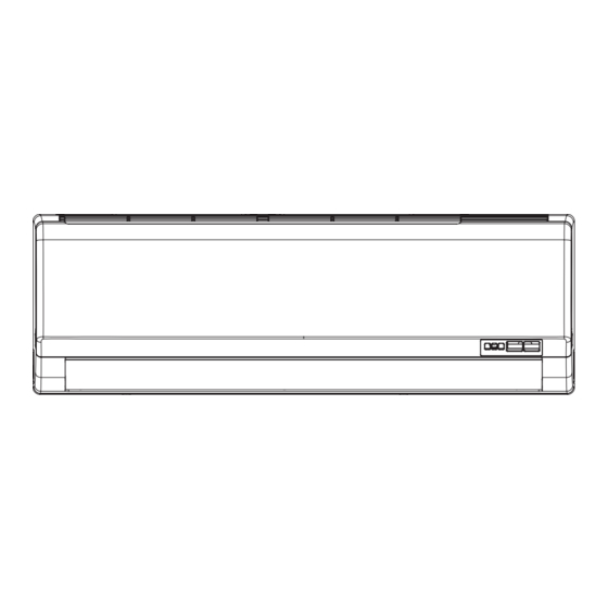
Service Manual 3. Outline Dimension Diagram 3.1 Indoor Unit 07K/09K(PA) Φ55 Φ55 09K(PB) Φ55 Φ55 Φ55 Φ55 Unit:mm Model 07K/09K(PA) 09K(PB) Technical Information... -
Page 20: Outdoor Unit
Service Manual 3.2 Outdoor Unit 07K/09K Unit:mm Unit:mm Technical Information... -
Page 21: Refrigerant System Diagram
side Valve Capillary Strainer Service Manual 4. Refrigerant System Diagram COOLING Cooling and heating model Outdoor unit Indoor unit Gas pipe side Valve 4-Way valve Di s charge Heat Suction Accumlator exchanger Compressor (evaporator) Heat exchanger Liquid pipe (condenser) side Valve Strainer Capillary... -
Page 22: Electrical Part
Note: Jumper cap is used to determine fan speed and the swing angle of horizontal lover for this model. ● Indoor Unit GWH07PA-K3NNA1F/I(CA414N02200) GWH09PA-K3NNA1F/I(CA414N02300) GWH07PA-K3NNA5F/I(CA417N01900) GWH09PA-K3NNA5F/I(CA417N02000) GWH12PC-K3NNA1F/I(CA414N02400) GWH12PC-K3NNA5F/I(CA417N02100) GWH09PA-K3NNA2F/I (CA415N03100) GWH09PB-K3NNA6E/I(CA430N00700) GWH12PC-K3NNA6E/I(CA430N00800) GWH07PA-K3NNA6E/I(CA430N00600) GWH07PA-K3NNA5E/I(CA417N01600) GWH09PB-K3NNA5E/I(CA417N01700) GWH12PC-K3NNA5E/I (CA417N01800) GWH07PA-K3NNA2E/I(CA415N01600) GWH09PB-K3NNA2E/I(CA415N01700) GWH12PC-K3NNA2E/I(CA415N01800) GWH07PA-K3NNA7F/I(CA428N00600) GWH09PA-K3NNA7F/I(CA428N00700) GWH12PC-K3NNA7F/I(CA428N00800) GWH07PA-K3NNA9E/I(CA429N00700) GWH09PB-K3NNA9E/I(CA429N00800) GWH12PC-K3NNA9E/I(CA429N00900) - Page 23 Service Manual GWH07PA-K3NNA6E/I(CA430N00601) GWH09PB-K3NNA6E/I(CA430N00701) GWH12PC-K3NNA6E/I(CA430N00801) GWH07PA-K3NNA2E/I(CA415N01601) GWH09PB-K3NNA2E/I(CA415N01701) GWH12PC-K3NNA2E/I(CA415N01801) GWH07PA-K3NNA7F/I(CA428N00601) GWH09PA-K3NNA7F/I(CA428N00701) GWH07PA-K3NNA5E/I(CA417N01601) GWH12PC-K3NNA5E/I(CA417N01801) GWH07PA-K3NNA9E/I(CA429N00701) GWH09PB-K3NNA9E/I(CA429N00801) GWH12PC-K3NNA9E/I(CA429N00901) GWH07PA-K3NNA1F/I(CA414N02201) GWH09PA-K3NNA1F/I(CA414N02301) GWH12PC-K3NNA1F/I(CA414N02401) GWH12PC-K3NNA7F/I(CA428N00801) GWH09PB-K3NNA5E/I(CA417N01701) GWH07PA-K3NNA3E/I(CA416N01600) GWH09PB-K3NNA3E/I(CA416N01700) GWH12PC-K3NNA3E/I(CA416N01800) BU(WH) BN(BK) RECEIVER AND ROOM TEMP. TUBE TEMP. DISPLAY BOARD SENSOR YEGN(GN) SENSOR POWER EARTH-PLATE YEGN YEGN...
- Page 24 Service Manual GWH07PA-K3NNA3E/I(CA416N01601) GWH12PC-K3NNA3E/I(CA416N01801) BU(WH) BN(BK) ROOM TEMP. FAN MOTOR TUBE TEMP. RECEIVER AND YEGN(GN) SENSOR SENSOR DISPLAY BOARD POWER EARTH-PLATE YEGN YEGN ROOM TUBE DISP1 EVAPORATOR AP1 PRINTED CIRCUIT BOARD N(1) AC-L COMP JUMP SWING-UD OFAN C0NNECTING CABLE HEALTH-L HEALTH-N TERMINAL BLOCK COOL PLASMA...
- Page 25 Service Manual GWH09MA-K3NNE4E/O(CA403W01500) GWH09NA-K3NNC7F/O(CA195W06300) GWH12NC-K3NNE4E/O(CA403W01600) GWH12NC-K3NNC7F/O(CA195W06400) These wiring diagrams are subject to change without notice; please refer to the one supplied with the unit. Technical Information...
-
Page 26: Pcb Printed Diagram
Service Manual 5.2 PCB Printed Diagram Technical Information... -
Page 27: Function And Control
Service Manual 6. Function and Control 6.1 Remote Controller Introduction of YX1F Buttons on Remote Controller ON/OFF button T-ON T-OFF MODE button AUTO SWING COOL SLEEP LOCK SPEED HEAT +/- botton MODE ON/OFF FAN button SWING SWING button SLEEP TIMER SLEEP button TIMER button Icon Display on Remote Controller... - Page 28 Service Manual When selecting auto mode, air conditioner will operate automatically according to ex-factory setting. Set temperature can't be adjusted and won't be displayed either. Press FAN button to adjust fan speed. (This function is not available in this air conditioner.) When selecting cool mode, air conditioner will operate under cool mode.
-
Page 29: Replacement Of Batteries In Remote Controller
Service Manual Replacement of Batteries in Remote Controller battery 1. Press the back side of remote controller on the spot marked with , and then push out the cover of battery box along the arrow direction. 2. Replace two No.7 (AAA 1.5V) dry batteries and make sure the positions of + and -- polar are correct. -
Page 30: Introduction For Icons On Display Screen
Service Manual 6.2 Remote Controller Introduction of YV1F7 Buttons on remote controller ON/OFF button ▲ button MODE button SWING button button FAN button TIMER OFF button CLOCK button TIMER ON button SLEEP button TEMP button TURBO button X-FAN button I FEEL button button Introduction for icons on display screen Set fan speed... - Page 31 Service Manual AUTO COOL HEAT Technical Information...
- Page 32 Service Manual battery reinstall remove Cover of battery box Technical Information...
- Page 33 Service Manual Technical Information...
-
Page 34: Remote Controller Introduction Of Yb1F2(Xfan)
Service Manual 6.3 Remote Controller Introduction of YB1F2(XFAN) ON/OFF Button AUTO HEALTH X-FAN MODE Button HUMIDITY FILTER +/- Button TURBO HOUR FAN Button ON/OFF Button Button ON/OFF MODE HEALTH SAVE Button X-FAN Button TEMP Button TIMER Button X-FAN TEMP TIMER TURBO Button TURBO SLEEP... - Page 35 Service Manual AUTO COOL DRY HEAT Auto no display (horizontal louvers stops at current position) Technical Information...
-
Page 36: Technical Information
Service Manual no display (horizontal louvers (swing angle is stops at current position) displayed dynamically) (swing angle is displayed dynamically) no display Technical Information... - Page 37 Service Manual Signal sender Battery Reinstall Cover of Remove battery box Technical Information...
-
Page 38: Brief Description Of Modes And Functions
Service Manual 6.4 Brief Description of Modes and Functions 1. Summary (1) Buzzer When the controller is energized or receives signal from button (emergency operation switch on air conditioner) or remote controller, the buzzer will give out a beep. (2) Display After energization, all icons will be displayed once. - Page 39 Service Manual that case, the compressor and the ODU fan stop operation, while the IDU operates at set fan speed. If freeze protection is released and the compressor has been out of operation for 3 mins, the unit will resume its previous operation status. Freeze protection period 3 min Compressor...
- Page 40 Service Manual ① Operation condition and process for fan mode In fan mode, the IDU fan motor operates at set speed, while the compressor and the ODU fan motor stop. 4-way valve is de-energized (4-way valve is not available for cooling only unit). Temperature setting range is 16~30℃ . ②...
- Page 41 Service Manual 3. Other Control Function Introduction (1)Timer function Controller has general timer function and clock timer function. When you select the remote controller with general timer function, only the general timer function of controller can be activated; when you select the remote controller with clock timer, only the clock timer function of controller can be activated.
-
Page 42: Special Function
Service Manual ③ When turning off the unit, horizontal louver will close at position O. ④ Swing action is valid only when set swing command and the IDU fan motor is operating. (8) Dual-8 nixie tube display ◆ When the air conditioner is turned on for the first time, dual-8 nixie tube defaulted to display current set temperature. ◆... -
Page 43: Notes For Installation And Maintenance
Service Manual Part Ⅱ : Installation and Maintenance 7. Notes for Installation and Maintenance Safety Precautions: 10. If the power cord or connection wire is not long enough, please get the specialized power cord or connection wire Important! from the manufacture or distributor. Prohibit prolong the wire by yourself. - Page 44 Service Manual Main Tools for Installation and Maintenance 1. Level meter, measuring tape 2. Screw driver 3. Impact drill, drill head, electric drill 4. Electroprobe 5. Universal meter 6. Torque wrench, open-end wrench, inner hexagon spanner 7. Electronic leakage detector 8.
-
Page 45: Installation Dimension Diagram
Service Manual 8. Installation 8.1 Installation Dimension Diagram Space to the wall Space to the wall At least 15cm At least 15cm Drainage pipe Installation and Maintenance... -
Page 46: Installation Procedures
Service Manual Installation procedures Start installation Preparation before installation Read the requirements select installation Prepare tools for electric connection location Select indoor unit Select outdoor unit installation location installation location Install the support of outdoor unit Install wall-mounting (select it according to the actual situation) frame, drill wall holes Connect pipes of indoor Fix outdoor unit... -
Page 47: Selection Of Installation Location
Service Manual 8.2 Installation Parts-checking 8.4 Electric Connection Requirement Name Name 1. Safety Precaution Indoor unit Sealing gum (1) Must follow the electric safety regulations when installing Outdoor unit Wrapping tape the unit. Support of outdoor (2) According to the local safety regulations, use qualified Connection pipe unit power supply circuit and air switch. - Page 48 Service Manual in the holes. 5. Connect the Pipe of Indoor Unit (3) Fix the wall-mounting frame on the wall with tapping screws (1) Aim the pipe joint at the corresponding bellmouth.(As show (ST4.2X25TA) and then check if the frame is firmly installed by in Fig.5) pulling the frame.
- Page 49 Service Manual 7. Connect Wire of Indoor Unit 8. Bind up Pipe (1) Open the panel, remove the screw on the wiring cover and (1) Bind up the connection pipe, power cord and drain hose then take down the cover.(As show in Fig.11) with the band.(As show in Fig.14) (2) Reserve a certain length of drain hose and power cord for installation when binding them.
-
Page 50: Installation Of Outdoor Unit
Service Manual 8.6 Installation of Outdoor unit Refer to the following table for wrench moment of force: Tightening torque(N . m) 1. Fix the Support of Outdoor Unit(Select it according to Hex nut diameter(mm) the actual installation situation) Φ6 15~20 Φ9.52 30~40 (1) Select installation location according to the house structure. -
Page 51: Vacuum Pumping And Leak Detection
Service Manual (3) The water outlet can't be placed in water in order to drain 8.8 Check after Installation and Test smoothly.(As show in Fig.27) operation 1. Check after Installation Check according to the following requirement after finishing installation. The drain hose can't be fluctuant Items to be checked Possible malfunction Has the unit been... -
Page 52: Error Code
Service Manual 9. Maintenance 9.1 Error code Display Method of Indoor Unit Indicator lamp (Only for the unit with indictor; Possible Causes(For specific maintenance Malfunction Error during blinking, ON for A/C Status method, please refer to the following procedure Name of troubleshooting) Code 0.5S and OFF for 0.5S) -
Page 53: Procedure Of Troubleshooting
Service Manual 9.2 Procedure of Troubleshooting 1. Malfunction of Temperature Sensor F1, F2 Main detection points: ● Is the wiring terminal between the temperature sensor and the controller loosened or poorly contacted? ● Is there short circuit due to trip-over of the parts? ●... - Page 54 Service Manual 2. Malfunction of Blocked Protection of IDU Fan Motor H6 Main detection points: ● SmoothlyIs the control terminal of PG motor connected tightly? ● SmoothlyIs the feedback interface of PG motor connected tightly? ● The fan motor can't operate? ●...
- Page 55 Service Manual 3. Malfunction of Protection of Jumper Cap C5 Main detection points: ● Is there jumper cap on the mainboard? ● Is the jumper cap inserted correctly and tightly? ● The jumper is broken? ● The motor is broken? ●...
- Page 56 Service Manual 4. Malfunction of Zero-crossing Inspection Circuit Malfunction of the IDU Fan Motor U8 Main detection points: ● Instant energization afte de-energization while the capacitordischarges slowly? ● The zero-cross detectioncircuit of the mainboard is defined abnormal? Malfunction diagnosis process: Start Turn power off for 1minute,the turn...
-
Page 57: Maintenance Method For Normal Malfunction
Service Manual 9.3 Maintenance method for normal malfunction 1. Air Conditioner Can't be Started Up Possible Causes Discriminating Method (Air conditioner Status) Troubleshooting Confirm whether it's due to power failure. If yes, No power supply, or poor After energization, operation indicator isn’t bright wait for power recovery. - Page 58 Service Manual 4. ODU Fan Motor Can't Operate Possible causes Discriminating method (air conditioner status) Troubleshooting Connect wires according to wiring diagram to Wrong wire connection, or poor Check the wiring status according to circuit make sure all wiring terminals are connected connection diagram firmly...
-
Page 59: Exploded View And Parts List
Service Manual 10. Exploded View and Parts List 10.1 Indoor Unit 07K/09K(PA) AUTO T-ON T-OFF HEALTH X-FAN AUTO SWING HUMIDITY COOL SLEEP FILTER LOCK SPEED HEAT TURBO HOUR ON/OFF ON/OFF MODE ON/OFF MODE MODE ON/OFF SWING SWING SLEEP TIMER TIMER ON CLOCK TIMER OFF TURBO... - Page 60 Service Manual Part Code Description GWH07PA-K3NNA6E/I Product Code CA430N00600 CA430000601 Air Louver 1 1051211302 1051211302 Air Louver 2 1051211402 1051211402 Helicoid Tongue 2611220202 2611220202 Left Axile Bush 10512037 10512037 Rear Case assy 22202254 22202254 Cross Flow Fan 10352034 10352034 O-Gasket of Cross Fan Bearing...
- Page 61 Service Manual Part Code Description GWH07PA-K3NNA5E/I Product Code CA417N01600 CA417N01601 Air Louver 1 1051211302 1051211302 Air Louver 2 1051211402 1051211402 Helicoid Tongue 2611220202 2611220202 Left Axile Bush 10512037 10512037 Rear Case assy 22202254 22202254 Cross Flow Fan 10352034 10352034 O-Gasket of Cross Fan Bearing 76512203 76512203 Ring of Bearing...
- Page 62 Service Manual Part Code Description GWH07PA-K3NNA2E/I Product Code CA415N01600 CA415N01601 Air Louver 1 1051211302 1051211302 Air Louver 2 1051211402 1051211402 Helicoid Tongue 2611220202 2611220202 Left Axile Bush 10512037 10512037 Rear Case assy 22202254 22202254 Cross Flow Fan 10352034 10352034 O-Gasket of Cross Fan Bearing 76512203 76512203 Ring of Bearing...
- Page 63 Service Manual Part Code Description GWH07PA-K3NNA7F/I Product Code CA428N00600 CA428N00601 Air Louver 1 1051211302 1051211302 Air Louver 2 1051211402 1051211402 Helicoid Tongue 2611220202 2611220202 Left Axile Bush 10512037 10512037 Rear Case assy 22202254 22202254 Cross Flow Fan 10352034 10352034 O-Gasket of Cross Fan Bearing 76512203 76512203 Ring of Bearing...
- Page 64 Service Manual Part Code Description GWH07PA-K3NNA9E/I Product Code CA429N00700 CA429N00701 Air Louver 1 1051211302 1051211302 Air Louver 2 1051211402 1051211402 Helicoid Tongue 2611220202 2611220202 Left Axile Bush 10512037 10512037 Rear Case assy 22202254 22202254 Cross Flow Fan 10352034 10352034 O-Gasket of Cross Fan Bearing 76512203 76512203 Ring of Bearing...
- Page 65 Service Manual Part Code Description GWH07PA-K3NNA3E/I Product Code CA416N01600 CA416N01601 Air Louver 1 1051211302 1051211302 Air Louver 2 1051211402 1051211402 Helicoid Tongue 2611220202 2611220202 Left Axile Bush 10512037 10512037 Rear Case assy 22202254 22202254 Cross Flow Fan 10352034 10352034 O-Gasket of Cross Fan Bearing 76512203 76512203 Ring of Bearing...
- Page 66 Service Manual Part Code Description GWH07PA-K3NNA1F/I Product Code CA414N02200 CA414N02201 Air Louver 1 1051211302 1051211302 Air Louver 2 1051211402 1051211402 Helicoid Tongue 2611220202 2611220202 Left Axile Bush 10512037 10512037 Rear Case assy 22202254 22202254 Cross Flow Fan 10352034 10352034 O-Gasket of Cross Fan Bearing 76512203 76512203 Ring of Bearing...
- Page 67 Service Manual Part Code Description GWH07PA-K3NNA5F/I GWH09PA-K3NNA5F/I Product Code CA417N01900 CA417N02000 Air Louver 1 1051211302 1051211302 Air Louver 2 1051211402 1051211402 Helicoid Tongue 2611220202 2611220202 Left Axile Bush 10512037 10512037 Rear Case assy 22202254 22202254 Cross Flow Fan 10352034 10352034 O-Gasket of Cross Fan Bearing 76512203 76512203...
- Page 68 Service Manual Part Code Description GWH09PA-K3NNA7F/I Product Code CA428N00700 CA428N00701 Air Louver 1 1051211302 1051211302 Air Louver 2 1051211402 1051211402 Helicoid Tongue 2611220202 2611220202 Left Axile Bush 10512037 10512037 Rear Case assy 22202254 22202254 Cross Flow Fan 10352034 10352034 O-Gasket of Cross Fan Bearing 76512203 76512203 Ring of Bearing...
- Page 69 Service Manual Part Code Description GWH09PA-K3NNA1F/I Product Code CA414N02300 CA414N02301 Air Louver 1 1051211302 1051211302 Air Louver 2 1051211402 1051211402 Helicoid Tongue 2611220202 2611220202 Left Axile Bush 10512037 10512037 Rear Case assy 22202254 22202254 Cross Flow Fan 10352034 10352034 O-Gasket of Cross Fan Bearing 76512203 76512203 Ring of Bearing...
- Page 70 Service Manual Part Code Description GWH09PA-K3NNA2F/I Product Code CA415N03100 Air Louver 1 1051211302 Air Louver 2 1051211402 Helicoid Tongue 2611220202 Left Axile Bush 10512037 Rear Case assy 22202254 Cross Flow Fan 10352034 O-Gasket of Cross Fan Bearing 76512203 Ring of Bearing 26152022 Evaporator Assy 01002577...
- Page 71 Service Manual 09K(PB) 37 38 AUTO T-ON T-OFF HEALTH X-FAN AUTO SWING HUMIDITY COOL SLEEP FILTER LOCK HEAT SPEED TURBO HOUR ON/OFF ON/OFF MODE ON/OFF MODE MODE ON/OFF SWING SWING SLEEP TIMER TIMER ON CLOCK TIMER OFF TURBO TEMP SLEEP X-FAN TEMP IFEEL...
- Page 72 Service Manual Part Code Description GWH09PB-K3NNA6E/I Product Code CA430N00700 CA430N00701 Front Panel Assy 2002275601 2002275601 Filter Sub-Assy 11122081 11122081 Screw Cover 2425201726 2425201726 Front Case Assy 2002223202 2002223202 Air Louver 1 1051211302 1051211302 Air Louver 2 1051211402 1051211402 Helicoid Tongue 2611216202 2611216202 Rear Case assy...
- Page 73 Service Manual Part Code Description GWH09PB-K3NNA5E/I Product Code CA417N01700 CA417N01701 Front Panel Assy 20022382 20022382 Filter Sub-Assy 11122081 11122081 Screw Cover 24252016 24252016 Front Case Assy 2002223201 2002223201 Air Louver 1 1051211302 1051211302 Air Louver 2 1051211402 1051211402 Helicoid Tongue 2611216202 2611216202 Rear Case assy...
- Page 74 Service Manual Part Code Description GWH09PB-K3NNA2E/I Product Code CA415N01700 CA415N01701 Front Panel Assy 20022292 20022292 Filter Sub-Assy 11122081 11122081 Screw Cover 24252016 24252016 Front Case Assy 2002223201 2002223201 Air Louver 1 1051211302 1051211302 Air Louver 2 1051211402 1051211402 Helicoid Tongue 2611216202 2611216202 Rear Case assy...
- Page 75 Service Manual Part Code Description GWH09PB-K3NNA9E/I Product Code CA429N00800 CA429N00801 Front Panel Assy 20022745 20022745 Filter Sub-Assy 11122081 11122081 Screw Cover 2425201726 2425201726 Front Case Assy 2002223202 2002223202 Air Louver 1 1051211302 1051211302 Air Louver 2 1051211402 1051211402 Helicoid Tongue 2611216202 2611216202 Rear Case assy...
- Page 76 Service Manual Part Code Description GWH09PB-K3NNA3E/I Product Code CA416N01700 Front Panel Assy 20022328 Filter Sub-Assy 11122081 Screw Cover 24252016 Front Case Assy 2002223201 Air Louver 1 1051211302 Air Louver 2 1051211402 Helicoid Tongue 2611216202 Rear Case assy 22202186 Rubber Plug (Water Tray) 76712012 O-Gasket sub-assy of Bearing 7651205102...
- Page 77 Service Manual AUTO T-ON T-OFF HEALTH X-FAN AUTO SWING HUMIDITY COOL SLEEP FILTER LOCK SPEED TURBO HEAT HOUR ON/OFF ON/OFF MODE ON/OFF MODE MODE ON/OFF SWING SWING SLEEP TIMER TIMER ON CLOCK TIMER OFF TURBO TEMP SLEEP X-FAN TEMP TIMER IFEEL X-FAN TURBO...
- Page 78 Service Manual Part Code Description GWH12PC-K3NNA6E/I Product Code CA430N00800 CA430N00801 Front Panel Assy 2002275701 2002275701 Display Board 30565120 30565120 Filter Sub-Assy 1112220403 1112220403 Screw Cover 2425201726 2425201726 Front Case Sub-assy 2002236101 2002236101 Air Louver 1 1051215603 1051215603 Air Louver 2 1051215503 1051215503 Helicoid Tongue...
- Page 79 Service Manual Part Code Description GWH12PC-K3NNA5E/I Product Code CA417N01800 CA417N01801 Front Panel Assy 20022360 20022360 Display Board 30565038 30565038 Filter Sub-Assy 1112220403 1112220403 Screw Cover 24252016 24252016 Front Case Sub-assy 20022361 20022361 Air Louver 1 1051215603 1051215603 Air Louver 2 1051215503 1051215503 Helicoid Tongue...
- Page 80 Service Manual Part Code Description GWH12PC-K3NNA2E/I Product Code CA415N01800 CA415N01801 Front Panel Assy 20022281 20022281 Display Board 30565211 30565211 Filter Sub-Assy 1112220403 1112220403 Screw Cover 24252016 24252016 Front Case Sub-assy 20022361 20022361 Air Louver 1 1051215603 1051215603 Air Louver 2 1051215503 1051215503 Helicoid Tongue...
- Page 81 Service Manual Part Code Description GWH12PC-K3NNA9E/I Product Code CA429N00900 CA415N01801 Front Panel Assy 2002274401 2002274401 Display Board 30565275 30565275 Filter Sub-Assy 1112220403 1112220403 Screw Cover 2425201726 2425201726 Front Case Sub-assy 2002236101 2002236101 Air Louver 1 1051215603 1051215603 Air Louver 2 1051215503 1051215503 Helicoid Tongue...
- Page 82 Service Manual Part Code Description GWH12PC-K3NNA3E/I Product Code CA416N01800 CA416N01801 Front Panel Assy 20022267 20022267 Display Board 30565212 30565212 Filter Sub-Assy 1112220403 1112220403 Screw Cover 24252016 24252016 Front Case Sub-assy 20022361 20022361 Air Louver 1 1051215603 1051215603 Air Louver 2 1051215503 1051215503 Helicoid Tongue...
- Page 83 Service Manual Part Code Description GWH12PC-K3NNA1F/I Product Code CA414N02400 CA414N02401 Front Panel Assy 20022275 20022275 Display Board 30565200 30565200 Filter Sub-Assy 1112220403 1112220403 Screw Cover 24252016 24252016 Front Case Sub-assy 20022361 20022361 Air Louver 1 1051215603 1051215603 Air Louver 2 1051215503 1051215503 Helicoid Tongue...
- Page 84 Service Manual Part Code Description GWH12PC-K3NNA7F/I Product Code CA428N00800 CA428N00801 Front Panel Assy 20022514 20022514 Display Board 30565110 30565110 Filter Sub-Assy 1112220403 1112220403 Screw Cover 242520179 242520179 Front Case Sub-assy 2001279001 2001279001 Air Louver 1 1051215603 1051215603 Air Louver 2 1051215503 1051215503 Helicoid Tongue...
- Page 85 Service Manual Part Code Description GWH12PC-K3NNA5F/I Product Code CA417N02100 Front Panel Assy 20022360 Display Board 30565038 Filter Sub-Assy 1112220403 Screw Cover 24252016 Front Case Sub-assy 20022361 Air Louver 1 1051215603 Air Louver 2 1051215503 Helicoid Tongue 2611216302 Left Axile Bush 10512037 Rear Case assy 22202467...
- Page 86 Service Manual 10.2 Outdoor Unit GWH07NA-K3NNC7F/O GWH07NA-K3NNE4E/O GWH09NA-K3NNC7F/O GWH09MA-K3NNE4E/O Installation and Maintenance...
- Page 87 Service Manual Part Code Description GWH07NA-K3NNC7F/O GWH07NA-K3NNE4E/O Product Code CA195W06200 CA403W01400 Front Grill 22263002 22263002 Cabinet 01433035P 01533255P Fan Motor 1501315604 1501315604 Chassis Sub-assy 0280322902P 02803229P Drainage Connecter 06123401 06123401 Compressor and Fittings 00106071 00106071 Magnet Coil 4300040047 4300040047 4-Way Valve 430004022 430004022 4-Way Valve Assy...
- Page 88 Service Manual Part Code Description GWH09NA-K3NNC7F/O GWH09MA-K3NNE4E/O Product Code CA195W06300 CA403W01500 Front Grill 22263002 22263002 Front Panel 01533255P 01533255P Fan Motor 1501315604 1501315604 Chassis Sub-assy 01700000127P 0280312301P Drainage Connecter 06123401 06123401 Compressor and Fittings 00101260 00103841 Magnet Coil 4300040047 4300040047 4-Way Valve 430004022 430004022...
- Page 89 Service Manual GWH12NC-K3NNE4E/O GWH12NC-K3NNC7F/O Installation and Maintenance...
- Page 90 Service Manual Description GWH12NC-K3NNE4E/O GWH12NC-K3NNC7F/O Product Code CA403W01600 CA195W06400 Front Grill 22413008 22413008 Front Panel 01533034P 01533034P Chassis Sub-assy 0280325701P 02803253P Drainage Connecter 06123401 06123401 Compressor and Fittings 00103937 00103937 Magnet Coil 4300040047 4300040047 4-way Valve Assy 03073310 03073140 4-way Valve 430004022 430004022 Strainer A...
-
Page 91: Removal Procedure
Service Manual 11. Removal Procedure Caution: discharge the refrigerant completely before removal. 11.1 Removal Procedure of Indoor Unit Note:Take A1 plane for example. Steps Procedure 1.Before disassembly Open the front panel . to remove it. Filter Remove axial sleeve of horizontal louver and bend the louver slightly. - Page 92 Service Manual Steps Procedure 3.Removal of indicator and front panel Remove connection screw of indicator and then remove the indicator. Screw Front Panel Assy Remove rotating shaft of front panel and then remove the front panel. 4.Removal of electric box cover 2 Screw Remove connection screws between electric box cover 2 and front case.
- Page 93 Service Manual Steps Procedure 5. Removal of front case Remove connection screws between front case and rear case. Screw Clasp Release clasp connecting front case and rear case and then remove the front case. 6. Removal of vertical louver Remove 10 clasps of vertical louver and rear case assy.
- Page 94 Service Manual Steps Procedure 7. Removal of electric box assy Indoor temp sensor Unplug indoor temp sensor. Electric box cover Remove connection screws of electric box assy and rear case. Release clasps and remove connection screws of earthing wire and evaporator assy. Then remove electric Electric box assy box assy.
- Page 95 Service Manual Steps Procedure Remove screws of step motor and then remove the motor. Step Motor Remove 4 connection screws of motor clamp and rear case. Then remove motor clamp. Motor Press Plat O-Gasket sub-assy of Bearing Removal of ring of bearing sub-assy. Ring of Bearing Removal of connection screws connecting motor.
-
Page 96: Removal Procedure Of Outdoor Unit
Service Manual 11.2 Removal Procedure of Outdoor Unit 07/09K Step Procedure 1. Remove big handle Remove the screw fixing big handle; slide out the big handle upwards to make the Right side plate clasp of big handle separate from the groove of right side plate, and then remove the big handle. - Page 97 Service Manual Step Procedure 4. Remove right side plate Protective grille Remove the screws fixing right side plate and then remove the right side plate. Right side plate Cut off the wire binder fixing the protective grille and then remove the protective grille. Screws Screws Screws...
- Page 98 Service Manual Step Procedure 7. Remove motor Motor Remove the screws fixing motor and then remove the motor. Screws 8. Remove motor support Motor support Remove the screws fixing motor support and then remove the motor support. Screws 9. Remove clapboard and soundproof sponge Clapboard Screws Remove the screws fixing clapboard and...
- Page 99 Service Manual Step Procedure 10. Remove magnetic coil Magnetic coil Remove one screw on magnetic coil, and then remove the magnetic coil. Screw 11. Remove gas valve and liquid valve Unsolder the spot weld between capillary with valve and condenser; remove two screws fixing the gas valve;...
- Page 100 Service Manual Step Procedure 13. Remove valve support Screw off the screw fixing the valve support and then remove the valve support. Valve support Screw 14.Remove compressor Compressor Remove 3 foot nuts on compressor, and then remove the compressor. Note: Protect the ports of discharge pipe and suction pipe to avoid foreign objects to enter it.
- Page 101 Service Manual 1. Before disassembly 2. Remove big handle Remove the connection screw fixing the big handle big handle and then remove the handle. 3. Remove top panel top panel Remove connection screws connecting the top panel with the front panel and the right side plate, and then remove the top panel.
- Page 102 Service Manual 4. Remove front grille Remove connection screws between the front grille and the front panel. Then remove the front grille . front grille 5. Remove front panel Remove connection screws connecting the front panel with the chassis and the motor support, and then remove the front panel.
- Page 103 Service Manual 8. Remove motor and motor suppor t motor suppor t Remove the 4 tapping screws fixing the motor and disconnect the leading wire insert of the motor. Then remove the motor. Remove the 2 tapping screws fixing the motor support and lift the motor support to remove it .
- Page 104 Service Manual 12. Remove magnet coil magnet coil Remove the screw fixing the magnet coil and then remove the coil. 13. Remove valves and 4-way valve subassembl y 4- wa y valv e Unsolder welding joint connecting the capillary, the valve and the outlet pipe of condenser to remove the capillary.
-
Page 105: Appendix
Service Manual Appendix: Appendix 1: Reference Sheet of Celsius and Fahrenheit Conversion formula for Fahrenheit degree and Celsius degree: Tf=Tcx1.8+32 Set temperature Fahrenheit Fahrenheit Fahrenheit display Fahrenheit display Fahrenheit display Fahrenheit Celsius( Celsius( Celsius( temperature temperature temperature 60.8 69/70 69.8 78/79 78.8 62/63... -
Page 106: Appendix 2: Pipe Expanding Method
Service Manual Appendix 2: Pipe Expanding Method Pipe Note: Pipe cutter Improper pipe expanding is the main cause of refrigerant leakage.Please expand the pipe according to the following steps: Leaning Uneven Burr A:Cut the pip ● Confirm the pipe length according to the distance of indoor unit and outdoor unit. ●... -
Page 107: Appendix 4: List Of Resistance For Temperature Sensor
Service Manual Appendix 4: List of Resistance for Temperature Sensor Resistance Table of Ambient Temperature Sensor for Indoor and Outdoor (15K) Temp( C) Resistance(kΩ) Temp( C) Resistance(kΩ) Temp( Resistance(kΩ) Temp( Resistance(kΩ) 138.1 18.75 3.848 1.071 128.6 17.93 3.711 1.039 121.6 17.14 3.579 1.009... - Page 108 Service Manual Resistance Table of Tube Temperature Sensors for Outdoor and Indoor (20K) Temp( C) Resistance(kΩ) Temp( C) Resistance(kΩ) Temp( Resistance(kΩ) Temp( Resistance(kΩ) 181.4 25.01 5.13 1.427 171.4 23.9 4.948 1.386 162.1 22.85 4.773 1.346 153.3 21.85 4.605 1.307 20.9 4.443 1.269 137.2...
- Page 109 Service Manual Resistance Table of Discharge Temperature Sensor for Outdoor (50K) Temp( C) Resistance(kΩ) Temp( Resistance(kΩ) Temp( C) Resistance(kΩ) Temp( Resistance(kΩ) 853.5 18.34 4.75 799.8 93.42 17.65 4.61 89.07 16.99 4.47 703.8 84.95 16.36 4.33 660.8 81.05 15.75 4.20 620.8 77.35 15.17 4.08...
- Page 110 GREE ELECTRIC APPLIANCES,INC.OF ZHUHAI Add: West Jinji Rd, Qianshan, Zhuhai, Guangdong, China 519070 Tel: (+86-756) 8522218 Fax: (+86-756) 8669426 Email: gree@gree.com.cn Http://www.gree.com HONG KONG GREE ELECTRIC APPLIANCES SALES LIMITED Add: Unit 2612,26/F.,Miramar Tower 132 Nathan Road,TST,Kowloon,HK Tel: (852) 31658898 Fax: (852) 31651029...