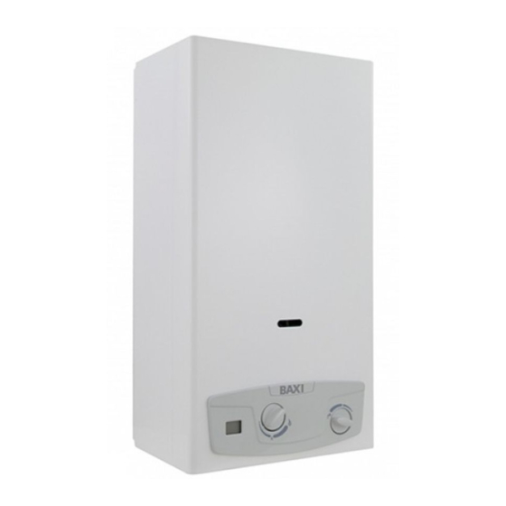
Advertisement
Advertisement

Summary of Contents for Baxi 11i
- Page 1 Baxi 11i Baxi 14i INSTALLATION, OPERATION AND MAINTENANCE MANUAL...
- Page 3 The device is well built in accordance with the current legislation. The CE sign positioned on the product indicates that it conforms to the following European Directives: 142/2009 93/68 0694 0694CP4791 WARNING This booklet contains information relevant to the user as well as the installer. The user must read the following chapters: General safety, Flue gas device and Operation.
-
Page 4: General Safety
Two knobs to attach to the control panel after installation stance Centre ahead of time to save wasting time and money afterwards. Water filter to insert in the water valve pipe fitting. 1. TECHNICAL CHARACTERISTICS 1.a Technical Data Baxi 11i Baxi 14i kcal/h kcal/h Nominal power usage (Pn) 19,0 16.340... - Page 5 Misure in mm B (Ø) Fig. 1 Flue gas release safety device Release hood Heat exchanger Ignition electrode Burner Hydraulic valve Temperature regulator Gas valve Gas input Gas adjustment screws Electronic devices Battery box Economiser Gas pressure intake Pilot burner Sensor Fig.
-
Page 6: Installation
2.c Room ventilation 2. INSTALLATION The installation of the water heater must comply with regulations in 2.a Regulations force including any updates. See paragraph 2.a The use of gas devices is controlled by precise regulations. Warning: This device can only be installed in venues that are per- It is essential to observe regulations in force. -
Page 7: E Gas Connection
2.e Gas Connection 2.g Disposal of waste product See paragraph 2.a This B11BS water heater is supplied with a device for releasing Determine the pipe diameter according to current regulations. flue gas. Before installing the device blow in the gas pipe to eliminate any For output of combustion by-products refer to the regulations in residue from its manufacturing. -
Page 8: H Gas Transformation
- Extract the large spring and the small spring/modulation valve set (fig. 14) - Substitute the modulation valve with the one in the kit - Insert the valve and the large spring, taking care with the di- rection of the insertion (fig. 16) and making sure that the drilled spring guide disc is in its correct position (fig. -
Page 9: Operation
(MIN ). Using the econo- Model 11i: for the extraction of 2.5 to 5.5 l/m the temperature of mizer limits the amount of heating when the hot water usage is mo- the water supplied remains at 60°C, (in this case the has valve sup-... -
Page 10: A Removing The Casing
4.a Removing the casing (Fig. 18) To remove the outer casing follow the steps below: - Remove the selector Knobs (A and B) - Remove the screws (C) - Shift the casing upwards to free it from the upper and lateral ho- - Shift the casing forwards - To reinsert the casing, follow the above steps in reverse order 4.b Troubleshooting: problems and solutions... -
Page 11: Serial Number Plate
IT-ES-PT-F: II2H3+ G20: 20 mbar Pn = Nominal power usage G30/G31: 28-30/37 mbar Qn = Nominal thermal range Baxi 11i Pm = Minimal power usage Qm = Minimal thermal range Pn = 19.0 O max = Maximum water pressure Qn = 21.8 Pm = 7.5...


