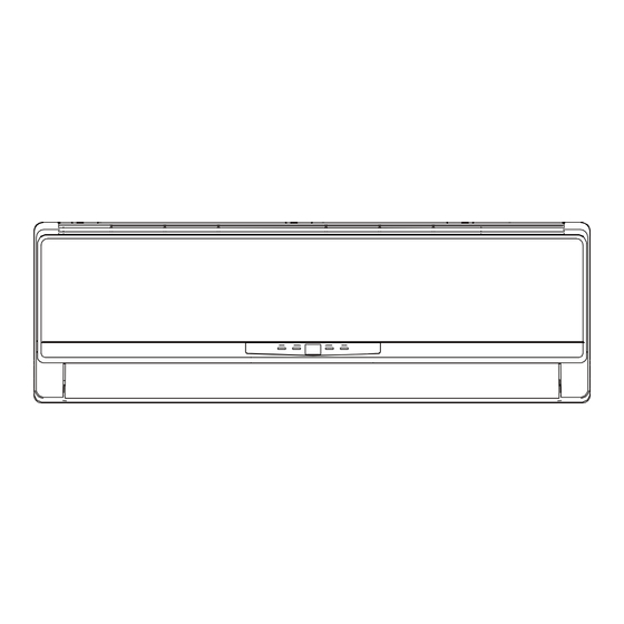
Summary of Contents for Gree GWH09MA-K3DNA2B
- Page 5 ON OFF MODE / FA N C LOCK TIMER ON X-F AN T EMP TIMER OF F T URBO SLEEP LIGH T...
- Page 13 Condition Cooling Condition Heating Indoor:DB26.7℃ WB19.4℃ Indoor:DB21.1℃ Indoor air flow: Super High Indoor air flow: Super High Pipe length:5m Pipe length:5m Compressor Speed (rps) Compressor Speed (rps) Condition Cooling Condition Heating Indoor:DB26.7℃ WB19.4℃ Indoor:DB21.1℃ Indoor air flow: Super High Indoor air flow: Super High Pipe length:5m Pipe length:5m Outdoor temp(℃)...
- Page 14 Indoor side noise when blowing Outdoor side noise when Compressor speed changed Supper High High Middle Indoor fan motor rotating speed Compressor Speed(rps)
- Page 17 GAS SIDE 3-WAY VALVE Muffler Di s charge HEAT EXCHANGE (EVAPORATOR) Suction Accumlator COMPRESSOR HEAT EXCHANGE (CONDENSER) LIQUID SIDE 2-WAY VALVE Capillary i a r t r e n COOLING GAS SIDE 3-WAY VALVE 4-Way valve Muffler Di s charge HEAT EXCHANGE (EVAPORATOR)
- Page 18 POWER DISPLAY ROOM TUBE TEM.SENSOR TEM.SENSOR YEGN CN1 CN2 W4BU N(1) DISP1 DISP2 W5BK ROOM TUBE COM-OUT W3BN YEGN W2YEGN AC-L L-OUT W1YEGN JUMP EVAPORATOR ELECTRIC BOX SWING-UD TR_OUT TR_IN ~ SWING MOTOR(U.D) TRANSFORMER FAN MOTOR...
- Page 19 POWER DISPLAY ROOM TUBE TEM.SENSOR TEM.SENSOR YEGN CN1 CN2 W1BU N(1) DISP-1 DISP-2 W3BK ROOM TUBE COM-OUT W2BN YEGN W4YEGN AC-L L-OUT W5YEGN JUMP EVAPORATOR ELECTRIC BOX SWING-UD HEALTH-L HEALTH-N COOL PLASMA ~ GENERATOR YEGN SWING MOTOR(U.D) FAN MOTOR TUBE OUTROOM EXHUAST TEM.SENSOR...
- Page 20 OUTROOM TUBE EXHUAST TEM.SENSOR TEM.SENSOR TEM.SENSOR YEGN YEGN LX1-1 LX1-2 AC-L2 AC-L5 AC-L4 AC-L3 AC-L AC-L AC-N1 AC-L1 AC-N AC-N2 COMU N(1) OVC-COMP AC-N3 YEGN OFAN W13 W14 W15 ELECTRIC BOX MID.ISOLATION SHEET FAN MOTOR W16 W17 W18 YEGN CT1,2 YEGN R(W) S(U) C(V) YEGN...
-
Page 24: Mode Icon
ON/OFF Press it to start or stop operation. MODE Press it to select operation mode (AUTO/COOL/DRY/FAN/HEAT). Press it to increase temperature setting. Press it to decrease temperature setting. Press it to set fan speed. Press it to set swing angle. TIMER ON Press it to set auto-on timer. -
Page 25: Fan Speed Display
LIGHT icon: is displayed by pressing the LIGHT button.Press LIGHT button again to clear the display. LOCK icon: is displayed by pressing "+" and “-” buttons simultaneously.Press them again to clear the display. SET TIME display: After pressing TIMER button, ON or OFF will blink.This area will show the set time. TURBO icon: is displayed when pressing theTURBO button.Press this button again to clear the display. -
Page 26: Replacement Of Batteries
TIMER ON: Press this button to initiate the auto-ON timer. To cancel the auto-timer program, simply press this button again. After pressing this button, disappears and "ON" blinks . 0 0:00 is displayed for ON time setting. Within 5 seconds, press + or - button to adjust the time value. - Page 27 Start cooling preset Original working state -2℃ preset Stop cooling 6 minutes 3 minutes 6 minutes Compresso r Outdoor fan Preset wind speed Indoor fan Stop...
- Page 30 Cooling angle Heating angle O(0°) O(0°)
- Page 34 Space to the ceiling 15cm Above Space to the wall 15cm Above 15cm Above Space to the wall 300cm Above Above Air outlet side Space to the floor The dimensions of the space necessary for correct ● installation of the appliance including the minimum permissible distances to adjacent structures Space to the obstruction Air inlet side...
- Page 35 Wall Wall Mark on the middle of it Gradienter Space Space to the to the wall wall above above Right Left Ф55mm Ф55mm (Rear piping hole) (Rear piping hole) Fig.1 Indoor Outdoor Wall pipe Seal pad outlet pipe of indoor unit outlet pipe of drain hose indoor unit...
- Page 36 External connection Gas side pipe electric wire Liquid side piping Gas side piping Tailing 2 Liquid side insulation Tailing 1 Piping insulation Finally wrap it Fig.3 Water drainage pipe with tape Left Right Left rear Fig.4 Right rear Fixing hook Mounting plate Mounting...
- Page 37 Manifold Valve Multimeter Manometer -76cmHg Hi handle Lo Handle Charging hose Low pressure valve Fig.6 Vacuum pump Drain-water hole Bottom frame Drain connecter Hose (available commercially, inner dia. 16mm)
- Page 38 Fig. a Fig. b Air filter Healthy filter Fig.


