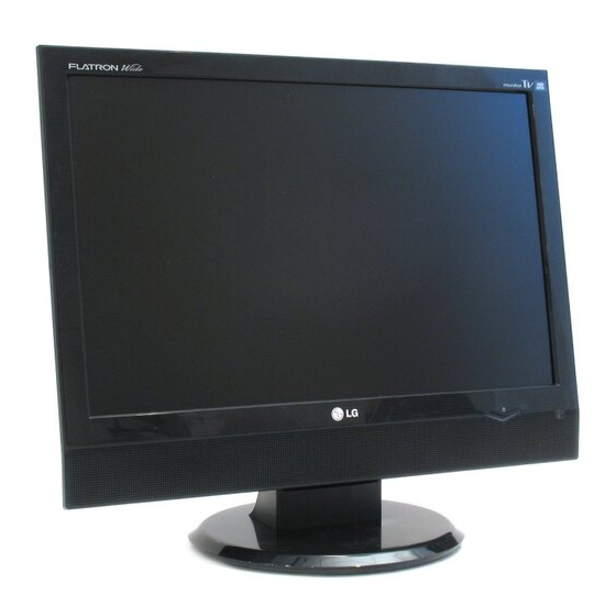
LG FLATRON M198WA Service Manual
Hide thumbs
Also See for FLATRON M198WA:
- Service manual (56 pages) ,
- User manual (50 pages) ,
- Brochure (34 pages)
Table of Contents
Advertisement
COLOR MONITOR
SERVICE MANUAL
Downloaded from
www.Manualslib.com
CHASSIS NO. : LP69G
MODEL:
*(
) **Same model for Service
CAUTION
BEFORE SERVICING THE UNIT,
READ THE SAFETY PRECAUTIONS IN THIS MANUAL.
manuals search engine
Website:http://biz.LGservice.com
M198WA (M198WA-BMH.A**MLP)
M228WA (M228WA-BMH.A**MLP)
Advertisement
Table of Contents

Related Manuals for LG FLATRON M198WA


Summary of Contents for LG FLATRON M198WA
- Page 1 Website:http://biz.LGservice.com COLOR MONITOR SERVICE MANUAL CHASSIS NO. : LP69G MODEL: M198WA (M198WA-BMH.A**MLP) M228WA (M228WA-BMH.A**MLP) ) **Same model for Service CAUTION BEFORE SERVICING THE UNIT, READ THE SAFETY PRECAUTIONS IN THIS MANUAL. Downloaded from www.Manualslib.com manuals search engine...
-
Page 2: Table Of Contents
CONTENTS CONTENTS ....................2 PRECAUTION ...................3 SPECIFICATION ..................7 DISASSEMBLY ..................14 ADJUSTMENT ..................16 SERVICE OSD ..................22 TROUBLE SHOOTING ................23 BLOCK DIAGRAM...................29 EXPLODED VIEW ...................32 REPLACEMENT PARTS LIST ............... 34 SVC. SHEET ....................- 2 - Downloaded from www.Manualslib.com manuals search engine... -
Page 3: Precaution
PRECAUTION WARNING FOR THE SAFETY-RELATED COMPONENT. WARNING BE CAREFUL ELECTRIC SHOCK ! • There are some special components used in LCD monitor that are important for safety. These parts are • If you want to replace with the new backlight (CCFL) or marked on the schematic diagram and the inverter circuit, must disconnect the AC adapter... -
Page 4: Servicing Precautions
SERVICING PRECAUTIONS CAUTION: Before servicing receivers covered by this 9. Use with this receiver only the test fixtures specified in service manual and its supplements and addenda, read this service manual. and follow the SAFETY PRECAUTIONS on page 3 of this CAUTION: Do not connect the test fixture ground strap publication. - Page 5 General Soldering Guidelines Replacement 1. Use a grounded-tip, low-wattage soldering iron and 1. Carefully insert the replacement IC in the circuit board. appropriate tip size and shape that will maintain tip 2. Carefully bend each IC lead against the circuit foil pad and solder it.
- Page 6 Circuit Board Foil Repair At Other Connections Excessive heat applied to the copper foil of any printed Use the following technique to repair the defective copper circuit board will weaken the adhesive that bonds the foil pattern at connections other than IC Pins. This technique to the circuit board causing the foil to separate from or involves the installation of a jumper wire on the "lift-off"...
-
Page 7: Specification
SPECIFICATION NOTE : Specifications and others are subject to change without notice for improvement. 1. Application range 3. Test method This specification is applied to 19"/22" Wide Monitor TV used LP69G chassis. 3.1 Performance : LGE test method followed 3.2 Demanded other specification 2. - Page 8 4.1.2 RGB/DVI Item Specification Remark Supported Sync. Type Separate Sync., Digital Operating Frequency Analog Horizontal 28 ~ 83kHz Vertical 56 ~ 75 Hz Digital Horizontal 28 ~ 83kHz Vertical 56 ~ 75 Hz Resolution(M198WA) Analog Max. 1440 x 900 @ 75Hz Recommend 1440 x 900 @ 60Hz Digital...
- Page 9 4-2. (LPL LM220WE1-TLA1, P/N:EAJ33945801 (ZBD)) - M228WA Module Specification Item Typ. Unit Remark Type TFT Color LCD Module Active Display area 473.76 (H) x 296.1 (V) Outline dimension 493.7 (H) x 320.1 (V) x16.5 (D) Pixel pitch 0.282mm (H) x 0.282mm (V) x RGB Color arrangement RGB vertical stripe Color Depth...
- Page 10 4.3.1 Optical Characteristic - M228WA Item Specification Remark Viewing Angle 70/70 80/80 <CR≥10> 60/70 75/85 Luminance PSM:Dynamic, CSM: 6500K RGB-PC Luminance Full White (100IRE) (cd/m AV/TV PSM:Dynamic, CSM:Cool Component Full White (100IRE) White Luminance Uniformity Contrast Ratio RGB-PC/ At DFC Mode AV/TV/ Typ.
- Page 11 5. Component Video Input (Y, PB, PR) Resolution H-freq(kHz) V-freq.(kHz) Pixel clock(MHz) Proposed 720*480 15.73 59.94 13.500 480i 720*480 15.75 60.00 13.514 480i 720*576 15.625 50.00 13.500 576i 720*480 31.47 59.94 27.000 480P 720*480 31.50 60.00 27.027 480P 720*576 31.25 50.00 27.000 576P...
- Page 12 7. RGB input ( DTV ) Resolution H-freq(kHz) V-freq.(kHz) Pixel clock(MHz) Proposed 720*480 31.47 59.94 27.000 480P 720*480 31.50 60.00 27.027 480P 720*576 31.25 50.00 27.000 576P 1280*720 37.5 50.00 74.250 720P 1280*720 44.96 59.94 74.176 720P 1280*720 45.00 60.00 74.250 720P 1920*1080...
- Page 13 9. DVI input (DTV) Resolution H-freq(kHz) V-freq.(kHz) Pixel clock(MHz) Proposed 720*480 31.47 59.94 27.000 480P 720*480 31.50 60.00 27.027 480P 720*576 31.25 50.00 27.000 576P 1280*720 37.5 50.00 74.250 720P 1280*720 44.96 59.94 74.176 720P 1280*720 45.00 60.00 74.250 720P 1920*1080 33.72 59.94...
-
Page 14: Disassembly
DISASSEMBLY 1. Push down slightly to disassembly it. Push the button. 2. After push the cable management like above fig.(Downward), Disassembly the Cable management with pulling it upward. 3. Disassembly Cable Holder. Hold the stand base. Disassembly Stand base. Remove base body Like a picture. Push 2 letches Like a picture. - Page 15 Pull base body to separate from set during pressing 2 letches. 1. Remove the screws. 2. Disassembly Hinge Cover. # 10 Remove the screws. Disassembly back cover. # 11 Pull the connector. - 15 - Downloaded from www.Manualslib.com manuals search engine...
-
Page 16: Adjustment Instruction
ADJUSTMENT INSTRUCTION 1. Application Range This specification sheet is applied to 19"/ 20"/ 22" LCD Monitor TV which is manufactured in TV (or Monitor) Factory or is produced on the basis of this data. 2. Specification 1) The adjustment is according to the order which is designated and which must be followed, according to the plan which can be changed only on agreeing. - Page 17 4.3. Confirm color coordinate of AV (1) Set Input to AV (2) Input signal : CVBS, NTSC @ 60Hz Full white 216/255 gray level (85 IRE, Model : 202, Pattern : 78 at MSPG925L) (3) Set PSM : Dynamic / CSM : Cool (4) Confirm whether x = 0.285±0.03, y = 0.293±0.03 or not.
- Page 18 (5) DVI 2) DIGITAL DATA 256Byte *M198WA - Select input DVI model 112(1440*900@60hz), 64 Gray Scale pattern and whether picture is displayed or not *M208WA / M228WA - Select input DVI model 122(1680*1050@60hz), 64Gray pattern and whether picture is displayed or not. 4.7.
- Page 19 * Area Option (M198WA/M208WA/M228WA-BMH) 4.11. Internal pressure Change by suffix : Area Option : South America - S.Am - Confirm whether is nomal or not when between power board's ac block and GND is impacked on 1.5kV(dc) or No. Item Condition Remark 2.2kV(dc) for one second.
- Page 20 5. Adjustment Command (2) Command Set 5.1. Adjustment Commands(LENGTH=84) Adjustment contents CMD(hex) ADH(hex) ADL(hex) Details EEPROM READ 0-Page 0~7F Read Adjustment Contents Description (hex) 0-Page 80~FF Read FACTORY ON Factory mode on 1-Page 0~7F Read FACTORY OFF Factory mode off 1-Page 80~FF Read EEPROM ALL INIT.
- Page 21 ADJUSTMENT Windows EDID V1.0 User Manual 2. EDID Read & Write 1) Run WinEDID.exe Operating System: MS Windows 98, 2000, XP Port Setup: Windows 98 => Don’t need setup Windows 2000, XP => Need to Port Setup. This program is available to LCD Monitor only. 1.
-
Page 22: Service Osd
SERVICE OSD BLUEBIRD3 - LP69G BLUEBIRD3 - LP69G Version 3.00 070502 Version 3.00 070502 M198WA WXGA+ LPL 19W M198WA WSXGA+ LPL 22W Tool Option 7809 Tool Option 7810 Area Option S.Am Area Option S.Am 2HR-OFF 2HR-OFF FACTORY-MODE FACTORY-MODE CHANNEL-MUTE CHANNEL-MUTE RAM Delay RAM Delay Power Off History... -
Page 23: Trouble Shooting
TROUBLESHOOTING GUIDE 1. NO POWER (LED INDICATOR OFF) : [A] Process Fail Check 15V or Check 15V or ST_5V of Power B/D. ST_5V of Power B/D. Pass Fail Fail Re-soldering of Change Check Output of Check short of defect part of IC100, Q307. IC1100, IC1101. - Page 24 2. NO RASTER : [B] Process Fail Check LED status Repeat A PROCESS. On Display Unit. Pass Fail Change Panel Link Cable Check Panel Link Cable or Module. or Module. Pass Check Inverter Fail Change Inverter Connector Connector or inverter. or Inverter.
- Page 25 3. NO RASTER ON RGB SINGAL Repeat [A, B] process. Pass Fail Check the input/ output Check the J701. of R708, R709 Pass Check Fail Re-soldering or Change the the input/output defect part. of R128, R131, R136. Pass Re-soldering or change the Fail Check the input/output of defect part, Check the...
- Page 26 4. No Raster on Component Signal Repeat [A, B] process. Fail Check the input/ output Check the J900. of R901. Pass Fail Re-soldering or Change the Check the input/output defect part. of R125. Pass Re-soldering or change the Fail Check the input/output of defect part, Check the IC100.
- Page 27 5. No Raster on DVI Signal Repeat [A, B] process. Pass Re-soldering or change the X100 Fail Check the input/ output defect part, Check the of R100. X100. Pass Check input source cable and jack. 6. No Raster on AV(Scart in 7.
- Page 28 8. No sound Fail Check the input Sourse. Change the source input. Pass Re-soldering of Change the Fail Check input/Output defect part, Check the ofIC100. X100 Pass Fail Re-soldering of Change Check the input/ output the defect part. of IC500 Pass Fail Change Speaker.
-
Page 29: Block Diagram
BLOCK DIAGRAM - 29 - Downloaded from www.Manualslib.com manuals search engine... -
Page 30: Description Of Block Diagram
DESCRIPTION OF BLOCK DIAGRAM 1. Power Supply Block (LIPS) This Block Generates DC Voltage (5V,15V) to Main Control system from AC Power (100-240 V, 50/60 Hz, 1.0A) 2. DC/DC Converter block DC/DC Converter convert the input 5V,15V to proper 1.8V,2.5V,3.3V,5V,10.5V for Main control system. For shooting heat trouble, we use the DC/DC converting IC 3. -
Page 31: Lips Board Block Diagram
LIPS Board Block Diagram 50 ~ 60Hz 100KHz HVDC ENERGY INPUT RECTIFIER OUTPUT RECTIFIER TRANSFER COMPONENTS AND FILTER AND FILTER LINE 100 ~ 240V SIGNAL PHOTO COLLENT- CONTROL -COUPLER CIRCUIT ISOLATION PRIMARY SECONDARY Operation description_LIPS 1. EMI components. This part contains of EMI components to comply with global marketing EMI standards like FCC,VCCI CISPR, the circuit included a line-filter, across line capacitor and of course the primary protection fuse. -
Page 32: Exploded View
EXPLODED VIEW - 32 - Downloaded from www.Manualslib.com manuals search engine... -
Page 33: Exploded View Parts List
Speaker,Full Range, L07030A-027 ND35 3W 16OHM 85DB 300HZ 30 X 70 X 22 SOLDER SUNLINK COMPANY EAJ36290801 LCD,Module-TFT, LM190WX1-TLC1 DRIVER 19INCH 1440X900 300CD COLOR 72% 16/10 850:1 5ms, MAGNA source D-IC, OKI gate D-IC, TLI T-con, 160/160, P7 LG PHILIPS LCD EAJ33945801 LCD,Module-TFT, LM220WE1-TLA1 DRIVER 22.0INCH 1680X1050 300CD COLOR 72% 16/10 800:1 160/160 5ms 4LAMPS LG PHILIPS LCD... -
Page 34: Replacement Parts List
REPLACEMENT PARTS LIST DATE: 2007. 06. 20. LOC. NO. PART NO. DESCRIPTION / SPECIFICATION LOC. NO. PART NO. DESCRIPTION / SPECIFICATION ACCESSORY C1124 0CE477EH618 "Capacitor,AL,RadialKMG5.0TP25VB47" MFL37805907 ManualPRINTING USER - BRAND M198W C1125 0CE107WF6DC "Capacitor,AL,ChipMVK6.3TP16VC100M" 6410TEW011A Power CordIMO LP-22 & H05VV-F 0.7 C1126 0CE227WF6DC "Capacitor,AL,ChipMVK8.0TP16VC220M"... - Page 35 LOC. NO. PART NO. DESCRIPTION / SPECIFICATION LOC. NO. PART NO. DESCRIPTION / SPECIFICATION C148 0CK473CK56A "Capacitor,Ceramic,ChipC1608X7R1H4" C205 0CK104CK56A "Capacitor,Ceramic,Chip0603B104K50" C149 0CK473CK56A "Capacitor,Ceramic,ChipC1608X7R1H4" C301 0CE107WF6DC "Capacitor,AL,ChipMVK6.3TP16VC100M" C150 0CK473CK56A "Capacitor,Ceramic,ChipC1608X7R1H4" C302 0CK103CK56A "Capacitor,Ceramic,Chip0603B103K50" C151 0CK473CK56A "Capacitor,Ceramic,ChipC1608X7R1H4" C303 0CC101CK41A "Capacitor,Ceramic,ChipC1608C0G1H1" C152 0CK473CK56A "Capacitor,Ceramic,ChipC1608X7R1H4"...
- Page 36 LOC. NO. PART NO. DESCRIPTION / SPECIFICATION LOC. NO. PART NO. DESCRIPTION / SPECIFICATION C528 0CC102CK41A "Capacitor,Ceramic,ChipC1608C0G1H1" D712 0DSON00138A "Diode,SchottkyMMBD301LT1G 600MV 3" C529 0CC102CK41A "Capacitor,Ceramic,ChipC1608C0G1H1" D713 0DSON00138A "Diode,SchottkyMMBD301LT1G 600MV 3" C530 0CC102CK41A "Capacitor,Ceramic,ChipC1608C0G1H1" D714 0DD184009AA Diode AssemblyKDS184 KDS184 TP KE C531 0CC102CK41A "Capacitor,Ceramic,ChipC1608C0G1H1"...
- Page 37 LOC. NO. PART NO. DESCRIPTION / SPECIFICATION LOC. NO. PART NO. DESCRIPTION / SPECIFICATION RESISTORs IC701 0IMMR00014A "IC,EEPROMM24C02-RMN6TP 2KBIT 256X" IC702 0IMMR00014A "IC,EEPROMM24C02-RMN6TP 2KBIT 256X" AR400 0RJ1000C687 "Resistor,ArrayRCA86TRJ100R 100OHM" AR401 0RJ1000C687 "Resistor,ArrayRCA86TRJ100R 100OHM" COILs & FILTERs & INDUCTORs AR410 0RJ1000C687 "Resistor,ArrayRCA86TRJ100R 100OHM"...
- Page 38 LOC. NO. PART NO. DESCRIPTION / SPECIFICATION LOC. NO. PART NO. DESCRIPTION / SPECIFICATION R1153 0RJ1053D477 "Resistor,ChipMCR03EZPF1053 105KOH" R193 0RJ1000D677 "Resistor,ChipMCR03EZPJ101 100OHM" R116 0RJ0472D677 "Resistor,ChipMCR03EZPJ470 47OHM 5" R194 0RJ1000D677 "Resistor,ChipMCR03EZPJ101 100OHM" R117 0RJ0472D677 "Resistor,ChipMCR03EZPJ470 47OHM 5" R196 0RJ1000D677 "Resistor,ChipMCR03EZPJ101 100OHM" R118 0RJ0472D677 "Resistor,ChipMCR03EZPJ470 47OHM 5"...
- Page 39 LOC. NO. PART NO. DESCRIPTION / SPECIFICATION LOC. NO. PART NO. DESCRIPTION / SPECIFICATION R316 0RJ1002D677 "Resistor,ChipMCR03EZPJ103 10KOHM" R706 0RJ0332D677 "Resistor,ChipMCR03EZPJ330 33OHM 5" R319 0RH2001D622 "Resistor,ChipMCR10EZHJ202 2KOHM 5" R707 0RJ0000D677 "Resistor,ChipMCR03EZPJ000 0OHM 5%" R320 0RH2001D622 "Resistor,ChipMCR10EZHJ202 2KOHM 5" R708 0RJ0682D677 "Resistor,ChipMCR03EZPJ680 68OHM 5"...
-
Page 40: Module
LOC. NO. PART NO. DESCRIPTION / SPECIFICATION LOC. NO. PART NO. DESCRIPTION / SPECIFICATION JACKs J1000 6612F00099A "Jack,PhonePEJ024-01 1P 4P STRAIGH" J1001 6612J10026A "Jack,RCARCA-359HA-00A-01G 14.0MM" J1002 6612F00024C "Jack,DINPSJ014-01 SOCKET 4P ANGLE" J1003 6612F00099A "Jack,PhonePEJ024-01 1P 4P STRAIGH" J900 6612J10031B "Jack,RCAPPJ209-01 14.0MM 1RX3C AN" SWITCHs SW2001 140-058E... -
Page 41: Printed Circuit Board
PRINTED CIRCUIT BOARD MAIN (TOP) - 41 - Downloaded from www.Manualslib.com manuals search engine... - Page 42 MAIN (BOTTOM) - 42 - Downloaded from www.Manualslib.com manuals search engine...
- Page 43 CONTROL LED & P/SW - 43 - Downloaded from www.Manualslib.com manuals search engine...
-
Page 44: Schematic Diagram
SCHEMATIC DIAGRAM 1. MSTAR - 44 - Downloaded from www.Manualslib.com manuals search engine... - Page 45 2. PANEL & CONNECTOR - 45 - Downloaded from www.Manualslib.com manuals search engine...
- Page 46 3. DDR - 46 - Downloaded from www.Manualslib.com manuals search engine...
- Page 47 4. AMP - 47 - Downloaded from www.Manualslib.com manuals search engine...
- Page 48 5. TUNER - 48 - Downloaded from www.Manualslib.com manuals search engine...
- Page 49 6. D-SUB & DVI - 49 - Downloaded from www.Manualslib.com manuals search engine...
- Page 50 7. SCART & DAC - 50 - Downloaded from www.Manualslib.com manuals search engine...
- Page 51 8. JACK - 51 - Downloaded from www.Manualslib.com manuals search engine...
- Page 52 9. POWER - 52 - Downloaded from www.Manualslib.com manuals search engine...
- Page 53 10. CONTROL KEY - 53 - Downloaded from www.Manualslib.com manuals search engine...
- Page 54 11. IR + LED + POWER - 54 - Downloaded from www.Manualslib.com manuals search engine...
- Page 55 Jun. 2007 P/NO : MFL38456749 Printed in Korea Downloaded from www.Manualslib.com manuals search engine...