Motorola CP040 Basic Service Manual
Commercial series
Hide thumbs
Also See for CP040:
- Detailed service manual (458 pages) ,
- Basic user's manual (292 pages) ,
- Service information (46 pages)

Related Manuals for Motorola CP040


Summary of Contents for Motorola CP040
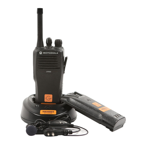
- Page 1 Commercial Series CP040 Portable Radio Basic Service Manual 6866549D14-A Issue: October 2004...
-
Page 2: Computer Software Copyrights
Accordingly, any copyrighted Motorola computer programs contained in the Motorola products described in this manual may not be copied or reproduced in any manner without the express written permission of Motorola. Furthermore, the purchase of Motorola... -
Page 3: Safety Information
Read this information before using the radio. PRODUCT SAFETY AND RF EXPOSURE FOR PORTABLE TWO-WAY RADIOS. This document provides information and instructions for the safe and efficient operation of Motorola Portable Two-Way Radios. The information provided in this document supersedes information contained in user guides published prior to February 2002. - Page 4 Compliance with RF Exposure Standards Your Motorola two-way radio is designed and tested to comply with a number of national and International standards and guidelines (listed below) for human exposure to radio frequency electromagnetic energy. This radio complies with the IEEE (FCC) and ICNIRP exposure limits for occupational/controlled RF exposure environments at operating duty factors of up to 50% talk- 50% listen and is authorized by the IEEE/ICNIRP for occupational use only.
- Page 5 Motorola - approved antennas, batteries and accessories may exceed IEEE/ICNIRP RF exposure guidelines. For a list of Motorola-approved antennas, batteries, and other accessories please see your dealer or local Motorola contact. Your nearest dealer can be found at the following web site: http://www.motorola.com/cgiss/emea/dealerlocator.html Additional Information For additional information on exposure requirements or other training information, visit http://www.motorola.com/rfhealth.
- Page 6 ELECTROMAGNETIC INTERFERENCE/COMPATIBILITY NOTE: Nearly every electronic device is susceptible to electromagnetic interference (EMI) if inadequately shielded, designed or otherwise configured for electromagnetic compatibility. Facilities To avoid electromagnetic interference and/or compatibility conflicts, turn off your radio in any facility where posted notices instruct you to do so. Hospitals or health care facilities may be using equipment that is sensitive to external RF energy.
-
Page 7: Operational Warnings
OPERATIONAL WARNINGS Vehicles with an air bag Refer to vehicle manufacturer's manual prior to installation of electronic equipment to avoid interference with air bag wiring. WARNING: Do not place a portable radio in the area over an air bag or in the air bag deployment area. -
Page 8: Intrinsically Safe Radio Information
Warnings for Radios Approved as Intrinsically Safe Radios must ship from the Motorola manufacturing facility with the hazardous atmosphere capability and the intrinsic safety approval labelling (FM, UL, CSA, CENELEC or ATEX). Radios will not be upgraded to this capability and labeled once they have been shipped to the field. - Page 9 The manual PN referenced on the Intrinsically Safe Approval Label identifies the approved Accessories and or options that can be used with that portable radio unit. Using a non Motorola intrinsically safe battery and or accessory with the Motorola approved radio unit will void the intrinsically safe approval of that radio unit.
-
Page 11: Table Of Contents
7.4 Dust Cover Assembly ................... 2-10 7.5 Chassis and Front Cover Assembly .............2-11 8.0 Mechanical View and Parts Lists ...............2-13 8.1 CP040 Exploded View and Parts List............2-13 9.0 Service Aids .......................2-15 10.0 Test Tools and Equipment .................2-16 11.0 Programming/Test Cable ..................2-17... - Page 12 Chapter 3 TRANSCEIVER PERFORMANCE TESTING 1.0 General ........................ 3-1 2.0 Setup ........................3-1 3.0 Test Mode ......................3-2 3.1 RF Test Mode ....................3-2 Chapter 4 RADIO TUNING AND PROGRAMMING 1.0 Introduction ......................4-1 2.0 CPS Programming/Flashing Setup with RIB ............4-1 3.0 CPS Programming Setup ..................
-
Page 13: Chapter 1 Introduction
In instances where the product is covered under a "return for replacement" or "return for repair" warranty, a check of the product should be performed prior to shipping the unit back to Motorola. This is to ensure that the product has been correctly programmed or has not been subjected to damage outside the terms of the warranty. -
Page 14: European Radio Support Centre (Ersc)
Aftermarket and Accessory Division (AAD). If no part number is assigned, the part is not normally available from Motorola. If the part number is appended with an asterisk, the part is serviceable by Motorola Depot only. If a parts list is not included, this generally means that no user-serviceable parts are available for that kit or assembly. -
Page 15: Technical Support
Warranty and Service Support Technical Support Motorola Product Services is available to assist the dealer/distributors in resolving any malfunctions which may be encountered. UK/Ireland - Richard Russell Telephone: +44 (0) 1256 488 082 Fax: +44 01256 488 080 Email: BRR001@email.mot.com... -
Page 16: Radio Model Information
INTRODUCTION Radio Model Information The model number and serial number are located on a label attached to the back of your radio. You can determine the RF output power, frequency band, protocols, and physical packages. The example below shows one mobile radio model number and its specific characteristics. Table 1-1 Radio Model Number (Example: MDH50KDC9AA2_N) Type of Model... -
Page 17: Chapter 2 Maintenance
Chapter 2 MAINTENANCE Introduction This chapter provides details about the following: Preventive maintenance (inspection and cleaning). Safe handling of CMOS and LDMOS devices. Disassembly and reassembly of the radio. Repair procedures and techniques. Preventive Maintenance The radios do not require a scheduled preventive maintenance program; however, periodic visual inspection and cleaning is recommended. -
Page 18: Safe Handling Of Cmos And Ldmos Devices
0180386A82), which includes a wrist strap, two ground cords, a table mat, and a floor mat. Wear a conductive wrist strap in series with a 100k resistor to ground. (Replacement wrist straps that connect to the bench top covering are Motorola part number 4280385A59) Do not wear nylon clothing while handling CMOS devices. -
Page 19: Repair Procedures And Techniques - General
When damaged parts are replaced, identical parts should be used. If the identical replacement part is not locally available, check the parts list for the proper Motorola part number and order the part from the nearest Motorola Parts centre listed in the “Piece Parts” section in Chapter 1 of this manual. -
Page 20: Radio Disassembly - Detailed
Remove the battery from the radio. 3. Remove the antenna. Battery Latch Lock Unlock Figure 2-1 Battery Removal 4. Pry off the volume and channel selector knobs from their shafts using the knob remover/chassis opener tool (Motorola part No.6686533Z01) (Figure 2.2). - Page 21 Radio Disassembly - Detailed Figure 2-2 Knob Removal NOTE: Both knobs slide on and off. However, they are supposed to fit very tightly on their shafts. 5. Separate the chassis from the front housing assembly by using the knob remover/chassis opener tool.
-
Page 22: Dust Cover Disassembly
MAINTENANCE Dust Cover Disassembly Gently pry the top of the dust cover away from the body of the radio (Figure 2.4). Rotate the dust cover 90° in a counter clockwise direction to allow the key to be removed. Separate the dust cover away from the body of the radio. The dust cover key is fragile; apply only light pressure to the key while removing the dust cover. -
Page 23: Ptt Disassembly
Radio Disassembly - Detailed PTT Disassembly 1. If required, the PTT (Figure 2-6) can be disassembled using a small screwdriver, as follows: Insert the tip of a small screwdriver underneath the PTT and unsnap the top tab. Pry the PTT away from the radio housing. Inspect the two hooks. -
Page 24: Chassis Disassembly
MAINTENANCE Chassis Disassembly CAUTION: Refer to the CMOS CAUTION paragraph (see 3.3) before removing the main board. Be sure to use Electrostatic Discharge protection when handling circuit boards. 1. Remove the O-ring. 2. Use a Torx™ screwdriver with a T6 bit to remove the four screws (Figure 2.7) holding the main board to the chassis. -
Page 25: Radio Assembly - Detailed
Radio Assembly — Detailed Radio Assembly — Detailed Chassis Assembly/Reassembly 1. Replace the battery contact seal (if necessary) surrounding the battery contact. 2. Remove the old Interface Pad from the chassis by scraping off the pad and adhesive with a straight razor. -
Page 26: Speaker Assembly
2-10 MAINTENANCE Speaker Reassembly 1. Align the speaker as shown in Figure 2.9. 2. Insert the top of the speaker under the two rails in the housing. 3. Place the speaker retainer bracket onto the two screw bosses. Make sure the tab fits into the retainer bracket slot. -
Page 27: Chassis And Front Cover Assembly
Radio Assembly — Detailed 2-11 Chassis and Front Cover Assembly 1. Dress and connect the speaker wires. NOTE: Care should be taken when dressing the speaker wires to avoid pinching them between the speaker magnet and shield, under the microphone boot or between the accessory connector and housing. - Page 28 2-12 MAINTENANCE 3. Push the chassis assembly completely into the top of the front cover (Figure 2-13) until it settles in place. Radio Chassis Figure 2-13 Fastening the Chassis 4. Make sure the O-ring is properly seated. 5. Snap the bottom of the chassis into the front cover. 6.
-
Page 29: Mechanical View And Parts Lists
Mechanical View and Parts List 2-13 Mechanical View and Parts List CP040 Exploded View and Parts List Figure 2-14 CP040 Radio Exploded View... - Page 30 Pad, PA interface Refer to Chapter Main Board Tanapa 7 - Model Charts 0386434Z01 Screws, speaker retainer; 2 used 0786433Z02 Retainer, speaker 5005679X04 Speaker 3586092Z02 Felt, speaker 4586439Z01 PTT, plastic 3886489Z01 PTT, rubber NON-REFERENCED ITEMS 3386488Z01 Nameplate, Motorola 3386409Z04 Nameplate, CP040...
-
Page 31: Service Aids
Table 2-1 lists the service aids recommended for working on the radio. While all of these items are available from Motorola, most are standard workshop equipment items, and any equivalent item capable of the same performance may be substituted for the item listed. -
Page 32: Test Equipment
2-16 MAINTENANCE 10.0 Test Equipment Table 2-2 lists test equipment required to service the CP040 Radio and other two-way radios. Table 2-2 Recommended Test Equipment Motorola Part No. Description Characteristics Application R2600 series Comms System This item will substitute for... -
Page 33: Programming/Test Cable
Programming/Test Cable 2-17 11.0 Programming/Test Cable 25 POSITION 25 POSITION MALE CONNECTOR FEMALE CONNECTOR 36.0” CABLE 36.0” CABLE Figure 2-15 Programming/Test Cable 12.0 Wiring of the Connectors 25 pin Male D Connector Components molded inside 2.5mm stereo and 3.5mm Orange 3.5mm Tip (Speaker +) Blue... - Page 34 2-18 MAINTENANCE...
-
Page 35: Transceiver Performance Testing
Chapter 3 TRANSCEIVER PERFORMANCE TESTING General These radios meet published specifications through their manufacturing process by utilizing high- accuracy laboratory-quality test equipment. The recommended field service equipment approaches the accuracy of the manufacturing equipment with few exceptions. This accuracy must be maintained in compliance with the manufacturer’s recommended calibration schedule. -
Page 36: Test Mode
TRANSCEIVER PERFORMANCE TESTING Test Mode RF Test Mode The RF Test Mode is a special routine that has been incorporated in the radio. This mode allows bench testing of the radio at various test frequencies across the entire band, at both high and low transmit power (if applicable), at various channel spacings, and with different coded or carrier squelch types. - Page 37 Test Mode Table 3-3 Test Channel Spacing No. of BKC Channel Spacing 25 kHz 12.5 kHz 20 kHz Table 3-4 Test Frequencies Channel Selector Test Channel VHF1 VHF2 UHF1 UHF2 UHF3 Switch Position 1 Low Power TX#1 or #8 136.625 146.625 403.625 438.625...
- Page 38 TRANSCEIVER PERFORMANCE TESTING Table 3-5 Receiver Performance Checks Test Name Communications Analyzer Radio Test Set Comments Reference Mode: PWR MON TEST MODE, PTT to continuous Frequency error to Frequency 4th channel test frequency Test Channel (during the be ±200 Hz VHF Monitor: Frequency error 4 carrier performance...
- Page 39 Test Mode Table 3-6 Transmitter Performance Checks Test Name Communications Analyzer Radio Test Set Comments Reference Mode: PWR MON TEST MODE, PTT to continuous Frequency error to be Frequency 4th channel test frequency Test Channel (during the ±200 Hz VHF Monitor: Frequency error 4 carrier performance...
- Page 40 TRANSCEIVER PERFORMANCE TESTING...
-
Page 41: Radio Tuning And Programming
Chapter 4 RADIO TUNING AND PROGRAMMING Introduction This chapter provides an overview of the Customer Programming Software (CPS) and tuner program designed for use in a Windows 98/ME/NT/2000/XP environment. A CPS/Tuner Installation Manual (6866549D08) is included in this Product Manual. CPS Programming/Flashing Setup with RIB A Windows 98/NT4/2000/ME/XP PC (personal computer) and Global Tuner are required to tune the radio. -
Page 42: Cps Programming Setup
RADIO TUNING AND PROGRAMMING CPS Programming Setup Refer to online help files for the CPS Programming procedures. Radio Test Box RLN4460 Battery Program/ Test Cable PMKN4004 Tx Data Data RLN4008 Computer Interface Cable RIB Power Supply Figure 4-2 CPS Programming Setup Radio to Radio Cloning Cloning is the process of copying the content of one radio (source radio) into another radio (destination radio). - Page 43 Radio to Radio Cloning Side Button 1 Side Button 2 Figure 4-3 Side Button Locations...
- Page 44 RADIO TUNING AND PROGRAMMING...
-
Page 45: Power Up Self-Test
Chapter 5 POWER UP SELF-TEST Self-Test Routine Turning on the radio using the on/off volume control starts a self-test routine which checks the RAM, EEPROM hardware and EEPROM checksum. Pressing and holding SB1 while turning on the radio causes the self-test routine to check for the ROM checksum as well. If these checks are successfully completed, the radio will generate the Self-Test Pass Tone. - Page 46 POWER UP SELF-TEST...
-
Page 47: Chapter 6 Accessories
Chapter 6 ACCESSORIES Accessories To order, refer to Chapter 1 (paragraph 2.4 - ‘Piece Parts’) of this manual. Antennas HAD9338AR VHF Heliflex Antenna 16cm (136-162 MHz) NAD6502 VHF Heliflex Antenna 15cm (146-174 MHz) HAD9742 VHF Stubby Antenna, 9cm (146-162 MHz) HAD9743 VHF Stubby Antenna, 7.5cm (162-174 MHz) NAE6522... -
Page 48: Headsets
ACCESSORIES 0180300E83 Body PTT Switch for Ear Mic Systems 0180358B33 Medium Earholder for Ear Mic Systems MDPMLN4442 Earbud with Microphone and PTT Combined MDPMLN4443 Flexible Ear Receiver with Microphone and PTT Combined Headsets PMMN4001 Ultra-Lite Earset with Mic and PTT PMLN4445 Ultra-light Headset with Boom Microphone RLN5238... -
Page 49: Chargers
Accessories Chargers MDWPLN4139 Desktop Rapid Charger 230V with Euro Plug MDWPLN4162 Rapid Multi Unit Charger 230V with Euro Plug MDWPLN4140 Desktop Rapid Charger 230V with UK Plug MDWPLN4163 Rapid Multi Unit Charger 230V with UK Plug MDWPLN4137 Desktop Rapid Charger (Base Only) EPNN7990 Power Supply for Desktop Rapid Charger (Base Only) (UK) EPNN7991... - Page 50 ACCESSORIES...
-
Page 51: Model Chart And Specification
Description PMUD1981_ CP040 136-162 MHz 5W 4-Ch Tanapa PMUD1982_ CP040 136-162 MHz 5W 16-Ch Tanapa PMLD4239_ CP040, Back Cover Kit 136-162 MHz 4-Ch PMLD4240_ CP040, Back Cover Kit 136-162 MHz 16-Ch PMLN4552_ Plain, Front Housing Kit, 4-Ch PMLN4553_ Plain, Front Housing Kit, 16-Ch... -
Page 52: Vhf1 136-162 Mhz Specifications
VHF1 136-162 MHz Specifications 2.0 VHF1 136-162 MHz Specifications FM Noise: -40 dB (12.5 kHz) -45 dB (25 kHz) General Receiver Frequency: 136-162 MHz 12.5 kHz 20/25kHz Channel Capacity: 4 or 16 Channels Frequency: 136-162 MHz 7.5 Volts ±20% Power Supply: 0.25 µV (typical) Sensitivity Dimensions:... - Page 53 Description PMUD1820_ CP040 146-174 MHz 5W 4-Ch Tanapa PMUD1822_ CP040 146-174 MHz 5W 16-Ch Tanapa PMLD4204_ CP040, Back Cover Kit 146-174 MHz 4-Ch PMLD4205_ CP040, Back Cover Kit 146-174 MHz 16-Ch PMLN4552_ Plain, Front Housing Kit, 4-Ch PMLN4553_ Plain, Front Housing Kit, 16-Ch...
-
Page 54: Specifications
VHF2 146-174 MHz Specifications 4.0 VHF2 146-174 MHz Specifications FM Noise: -40 dB (12.5 kHz) -45 dB (25 kHz) General Receiver Frequency: 146-174 MHz 12.5 kHz 20/25kHz Channel Capacity: 4 or 16 Channels Frequency: 146-174 MHz 7.5 Volts ±20% Power Supply: 0.25 µV (typical) Sensitivity Dimensions:... - Page 55 Description PMUE1984_ CP040 403-440 MHz 4W 4-Ch Tanapa PMUE1985_ CP040 403-440 MHz 4W 16-Ch Tanapa PMLE4297_ CP040, Back Cover Kit 403-440 MHz 4-Ch PMLE4298_ CP040, Back Cover Kit 403-440 MHz 16-Ch PMLN4552_ Plain, Front Housing Kit, 4-Ch PMLN4553_ Plain, Front Housing Kit, 16-Ch...
-
Page 56: 6.0 Uhf1 403-440 Mhz Specifications
UHF1 403-440 MHz Specifications 6.0 UHF1 403-440 MHz Specifications Receiver UHF1 UHF1 General 12.5 kHz 20/25kHz UHF1 Frequency: 403-440 MHz Frequency: 403-440 MHz 0.25 µV (typical) Sensitivity 12dB EIA SINAD: Channel Capacity: 4 or 16 Channels 7.5 Volts ±20% Adjacent Channel -60 dB -70 dB Power Supply:... - Page 57 Description PMUE1949_ CP040 438-470 MHz 4W 4-Ch Tanapa PMUE1951_ CP040 438-470 MHz 4W 16-Ch Tanapa PMLE4255_ CP040, Back Cover Kit 438-470 MHz 4-Ch PMLE4254_ CP040, Back Cover Kit 438-470 MHz 16-Ch PMLN4552_ Plain, Front Housing Kit, 4-Ch PMLN4553_ Plain, Front Housing Kit, 16-Ch...
-
Page 58: 8.0 Uhf2 438-470 Mhz Specifications
UHF2 438-470 MHz Specifications 8.0 UHF2 438-470 MHz Specifications Receiver UHF2 UHF2 General 12.5 kHz 20/25kHz UHF2 Frequency: 438-470 MHz Frequency: 438-470 MHz 0.25 µV (typical) Sensitivity 12dB EIA SINAD: Channel Capacity: 4 or 16 Channels 7.5 Volts ±20% Adjacent Channel -60 dB -70 dB Power Supply:... - Page 59 Description PMUE1986_ CP040 465-495 MHz 4W 4-Ch Tanapa PMUE1987_ CP040 465-495 MHz 4W 16-Ch Tanapa PMLE4299_ CP040, Back Cover Kit 465-495 MHz 4-Ch PMLE4300_ CP040, Back Cover Kit 465-495 MHz 16-Ch PMLN4552_ Plain, Front Housing Kit, 4-Ch PMLN4553_ Plain, Front Housing Kit, 16-Ch...
-
Page 60: 10.0 Uhf3 465-495 Mhz Specifications
7-10 UHF3 465-495 MHz Specifications 10.0 UHF3 465-495 MHz Specifications Receiver UHF3 UHF3 General 12.5 kHz 20/25kHz UHF3 Frequency: 465-495 MHz Frequency: 465-495 MHz 0.25 µV (typical) Sensitivity 12dB EIA SINAD: Channel Capacity: 4 or 16 Channels 7.5 Volts ±20% Adjacent Channel -60 dB -70 dB... -
Page 61: Mil Standards
MIL Standards 7-11 11.0 MIL Standards MIL STDS 810 C, D, E, and F: Applicable to UHF and VHF Specifications (8.2 and 8.4) Military Standards 810 C, D, E, & F: Parameters/Methods/Procedures 810C 810D 810E 810F Applicable Methods Procedures Methods Procedures Methods Procedures... - Page 62 7-12 MODEL CHART AND SPECIFICATION...
-
Page 63: Glossary
Micro Controller Unit MRTI Motorola Radio-Telephone Interconnect: a system that provides a repeater connection to the Public Switched Telephone Network (PSTN). The MRTI al- lows the radio to access the telephone network when the proper access code... - Page 64 Glossary OMPAC Over-Molded Pad-Array Carrier: a Motorola custom package, distinguished by the presence of solder balls on the bottom pads. PC Board Printed Circuit Board Private-Line® tone squelch: a continuous sub-audible tone that is transmitted along with the carrier. Phase-Locked Loop: a circuit in which an oscillator is kept in phase with a ref- erence, usually after passing through a frequency divider.
- Page 65 Glossary µP Microprocessor Voltage-Controlled Oscillator: an oscillator whereby the frequency of oscillation can be varied by changing a control voltage. VCOBIC Voltage-Controlled Oscillator Buffer Integrated Circuit Very High Frequency VSWR Voltage Standing Wave Ratio...
- Page 66 Glossary...