Table of Contents
Advertisement
SERVICE
YEPP
YP-U4
Refer to the service manual in the GSPN (see the rear cover) for the more information.
YEPP
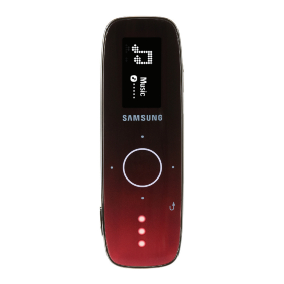
Model Name : YP-U4
Model Code : YP-U4JAB/EDC
Manual
1. Precaution
2. Product Specification
3. Disassembly & Reassembly
4. Troubleshooting
5. Exploded View & Part List
6. PCB Diagram
7. Schematic Diagram
CONTENTS
Advertisement
Table of Contents

Related Manuals for Samsung YP-U4


Summary of Contents for Samsung YP-U4
- Page 1 YEPP Model Name : YP-U4 Model Code : YP-U4JAB/EDC SERVICE Manual YEPP CONTENTS 1. Precaution 2. Product Specification 3. Disassembly & Reassembly 4. Troubleshooting 5. Exploded View & Part List 6. PCB Diagram 7. Schematic Diagram YP-U4 Refer to the service manual in the GSPN (see the rear cover) for the more information.
- Page 2 Asia asia.samsungportal.com Mideast & Africa mea.samsungportal.com © Samsung Electronics Co.,Ltd. Aug. 2008 This Service Manual is a property of Samsung Electronics Printed in Korea Co.,Ltd. Any unauthorized use of Manual can be punished under applicable International and/or domestic law.
-
Page 3: Table Of Contents
Contents 1. Precaution 1-1 Safety Precautions ................... 1-1 1-2 Static Electricity Precautions ................1-2 2. Product Specification 2-1 Product Feature ....................2-1 2-2 Specifications ....................2-2 2-3 Specifications Analysis ..................2-3 2-4 Accessories ......................2-4 3. Disassembly & Reassembly 3-1 Overall Disassembly & Reassembly ..............3-1 4. -
Page 4: Precaution
5. You should not put any object or liquid into product. Otherwise, it may cause failure or mal-operation. 6. If replacement material is required, service engineer should use materials with the same standard. The use of non-standardized materials may cause failure of product. Samsung Electronics... -
Page 5: Static Electricity Precautions
4. Minimize physical operation when handling with the ESD device for replacement without packing (Otherwise, namely friction between cloth fibers or lifting of the foot from the carpet floor may cause static electricity enough to damage the ESD device). Samsung Electronics... -
Page 6: Product Specification
- Voice Recording - Playback Speed Adjustment - Interval Skip Playback - (A-B) Section Repeat - Data Cast Usability - Recently added playlist - User Button - DNSe 2.0 Semiautomatic Sliding USB Light Effect Using White-LED 4Line 16-Gray OLED Display (128 x 64) Sleek Touch Pad Samsung Electronics... -
Page 7: Specifications
(based on: MP3 128kbps, Volume: 15, Normal Mode, Display Off) Temperature Range for -5 ~ 35°C (23~95°F) Operation Case Plastics Weight 0.97 oz 1.06˝ x 3.27˝ x 0.51˝ Dimensions (W x H x D) FM Frequency 87.5 ~ 108.0MHz FM Signal to 55 dB Noise Ratio FM Radio FM T.H.D FM Useable 38dBu Sensitivity Samsung Electronics... -
Page 8: Specifications Analysis
Tact Key: Play (Power)/Rec (User) Touch: FF/REW/Select/Vol+/Vol-/Back Touch: FF/REW/Menu/Vol+/Vol- External Material IN-Mold Surface Deposition, IN-Mold Accessory EP-370/Quick Guide/Install CD EP-360/Quick Guide/Install CD PC Software Samsung Media Studio Samsung Media Studio Minimum System Windows 2000/XP/Vista Windows SE/ME/2000/XP Requirements Pentium 500MHz Pentium 133MHz Samsung Electronics... -
Page 9: Accessories
Product Specification 2-4 Accessories 2-4-1 Supplied Accessories Accessories Item Item code Remark Earphones AH59-01884A Samsung Service Center AH46-00058C Program Installation CD Samsung Electronics... -
Page 10: Disassembly & Reassembly
When separating them, be careful not to make scratches. 2) Press on the disassembling tool and lift the ASSY-WINDOW LCD. 3) Lift the Connector Locker and then remove the ASSY-WINDOW LCD. Samsung Electronics... - Page 11 2) Lift and remove the FRAME by the part where the pin set appears. MAIN PCB 1) Remove the USB FPCB, then hold the ASSY CABINET-BACK by the top and bottom and lift and remove the MAIN PCB. 2) Appearance when disassembly is complete. Samsung Electronics...
-
Page 12: Troubleshooting
Troubleshooting 4. Troubleshooting 4-1 Checkpoints by Error Mode ..............4-2 4-2 Upgrade Methods .................4-14 Samsung Electronics... -
Page 13: Checkpoints By Error Mode
Does the X-TAL1 CLOCK appear? TP1, TP2 Check Refer to wave pattern Refer to wave pattern image of Fig. 4-3. image of Fig. 4-2. Defective Check the charge in the BATTERY unit Replace BATTERY and check again Done Samsung Electronics... - Page 14 Troubleshooting MIC1 Voltage/DIV: 1.0V/div CON2 TIME/DIV: 500us/div IC12 MAIN Page, 7-3 Voltage/DIV: 1.0V/div TIME/DIV: 500us/div MAIN PCB Bottom Page, 6-4 <Fig. 4-1> Samsung Electronics...
- Page 15 Troubleshooting Voltage/DIV: 0.5V/div TIME/DIV: 20us/div MIC1 CON2 MAIN Page, 7-3 IC12 MAIN PCB Bottom Page, 6-4 <Fig. 4-2> Samsung Electronics...
- Page 16 Troubleshooting Voltage/DIV: 2.0V/div TIME/DIV: 100us/div MAIN 7-3 Page MIC1 CON2 IC12 MAIN PCB Bottom 6-4 Page <Fig. 4-3> Samsung Electronics...
- Page 17 Refer to wave pattern image of Fig. 4-4. Can audio stoppage or interference be heard? Can it be heard when playing other files? Do the symptoms appear even after upgrading to the latest firmware? Replace Board. (Requires close inspection) Finished Samsung Electronics...
- Page 18 Troubleshooting Voltage/DIV: 0.5V/div TIME/DIV: 500ms/div MAIN Page, 7-3 MIC1 CON2 IC12 MAIN PCB Bottom Page, 6-4 <Fig. 4-4> Samsung Electronics...
- Page 19 Is there a USB mass Is there a "U4" storage device in the portable disk? "Device Manager"? Is there a "YP-U4 USB Does it update with Device" in "Disk Drives"? the "Updater"? Does it connect Check if any collision for the after replacing the BOTTOM disk drive volume.
- Page 20 Disassemble it and check if the Do the TOUCH KEYS respond? TOUCH FPCB is properly connected to the Connector Is the TOUCH PAD malfunctioning? Done Disassemble the body and check if the TOUCH PAD has come loose from the device Samsung Electronics...
-
Page 21: Upgrade Methods
- Files are corrupted, or the product shows as a “removable storage” in Windows but cannot be accessed. 4-2-1 Firmware Upgrade Method 1. Press the “YP-U4 Updater” icon in the background and run the program. 2. Run the "YP-U4 Updater" program. 3. Press the "RESET" switch on the back of the set. - Page 22 9. Go to "Settings → System → System Info" and check the firmware version. If there is not enough battery, the upgrade will not proceed. If this occurs, you must connect the USB or the charging cord for it to proceed properly. Samsung Electronics 4-11...
- Page 23 MEMO 4-12 Samsung Electronics...
-
Page 24: Exploded View & Part List
Exploded View & Part List 5. Exploded View & Part List 5-1 Exploded View ..................5-2 5-2 Electrical Part List ................5-4 Samsung Electronics This Document can not be used without Samsung’s authorization. -
Page 25: Exploded View
Exploded View & Part List 5-1 Exploded View AS040 AK416 AC000 AK415 AC010 AP085 AK200 AK315 AK280 This Document can not be used without Samsung’s authorization. Samsung Electronics... - Page 26 AH64-04664A KNOB-RESET;YP-U4,PC,T2.4,W14.0,L11.0,-,B AK415 AH64-04663A KNOB-USB;YP-U4,PC,T2.4,W10.0,L3.0,-,BLA AK416 AH64-04328A KNOB-USB SPRING;YP-U3,SWP-B,T0.3mm,-,-,- AP085 AH61-02618A PLATE-REFLECT;YP-U4,PC/ACRYL,T0.5,W8.6,L AS040 6003-001166 SCREW-TAPTITE;CH,+,B,M1.4,L4,NI PLT,SWRC HINGE AH97-02692A ASSY HINGE-USB;-,HINGE-USB,ASSY HINGE-US AH07-00233A OLED PM;-,-,64*128,YP-U4,18*36.5*1.67m PCB-MAIN AH92-02856A ASSY PCB;-,YP-U4,4G FM,- Samsung Electronics This Document can not be used without Samsung’s authorization.
-
Page 27: Electrical Part List
R22 2007-000155 R-CHIP;27Kohm,5%,1/16W,TP,1005 C59 2203-006979 C-CER,CHIP;10nF,10%,10V,X7R,0603 R23 2007-007456 R-CHIP;619ohm,1%,1/16W,TP,1005 2203-005900 C-CER,CHIP;1000NF,+80-20%,10V,Y5V,1 R24 2007-008483 R-CHIP;47Kohm,5%,1/20W,TP,0603 C60 2203-000278 C-CER,CHIP;0.01nF,0.5pF,50V,C0G,100 C61 2203-000278 C-CER,CHIP;0.01nF,0.5pF,50V,C0G,100 R25 2007-000163 R-CHIP;120Kohm,5%,1/16W,TP,1005 R26 2007-008052 R-CHIP;4.7Kohm,5%,1/20W,TP,0603 C62 2203-006890 C-CER,CHIP;10000nF,20%,6.3V,X5R,160 This Document can not be used without Samsung’s authorization. Samsung Electronics... - Page 28 1405-001093 VARISTOR;14V,20A,1x0.5x0.6mm,TP VAR2 1405-001093 VARISTOR;14V,20A,1x0.5x0.6mm,TP VAR5 1405-001093 VARISTOR;14V,20A,1x0.5x0.6mm,TP X-TAL1 2801-003856 CRYSTAL-SMD;0.032768MHz,20ppm,28-AC X-TAL2 2801-004285 CRYSTAL-SMD;24MHz,30ppm,28-ACO,12pF X-TAL3 2801-003856 CRYSTAL-SMD;0.032768MHz,20ppm,28-AC ZD1 0406-001254 DIODE-TVS;UCLAMP0501P,6/-/-V,200W,S AH99-10013K ASSY AUTO INSERT-PCB;-,YP-U4,-,-,AH AH98-00015A ASSY ACCESSORY;MP3,YP-U4,XET,- AH46-00058C S/W APPLICATION;-,YP-U4,-,-,FRENCH, AH59-01884A EARPHONE-EP-380;EP-380(BLACK),EP-38 AH68-00650L MARK RECYCLE-CARD-WARRANTY;YP-P2,EL 1 AH68-01933Q MANUAL USERS-EMODIO CARD;YP-P2,XSP, Samsung Electronics This Document can not be used without Samsung’s authorization.
- Page 29 MEMO Samsung Electronics...
-
Page 30: Pcb Diagram
PCB Diagram 6. PCB Diagram 6-1 MAIN PCB Top ....................6-2 6-2 MAIN PCB Bottom .................... 6-4 Samsung Electronics... -
Page 31: Main Pcb Top
PCB Diagram 6-1 MAIN PCB Top CON5 IC10 LCD CONNECTOR CON3 FLASH MEMORY USB FPCB CONNECTOR TOUCH KEYPAD CONNECTOR Samsung Electronics... - Page 32 Signal VCOMH VBREF IREF RESET USB5V PBA_CE 4 CON4 D[0] TOUCH KEYPAD CONNECTOR D[1] Pin No. Signal D[2] MENU KEY D[3] LED2 D[4] LED3 D[5] VDD_BATT D[6] LED1 D[7] FF KEY LCD_TP VOLUME - SEL KEY REW KEY VOLUME+ Samsung Electronics...
-
Page 33: Main Pcb Bottom
PCB Diagram 6-2 MAIN PCB Bottom MIC1 CON2 IC12 BATTERY CONNECTOR FM IC MAIN IC SDRAM OLED POWER IC TOUCH SENSOR IC OVP IC RESET S/W Samsung Electronics... - Page 34 PCB Diagram 6-2-1 Test Point Wave Form Samsung Electronics...
- Page 35 MEMO Samsung Electronics...
-
Page 36: Schematic Diagram
Schematic Diagram 7. Schematic Diagram 7-1 Overall Block Diagram ..................7-2 7-2 MAIN ........................7-3 Samsung Electronics This Document can not be used without Samsung’s authorization. -
Page 37: Overall Block Diagram
The power supply uses a 5V power input through an internal battery, USB power or an adapter. 3.2V AMBA AHB TOUCH OLED SDRAM FLASH MEMORY FM Tuner SENSOR (128*64) (K4M281633) 16Gbit(2,4GB) (Si4703) (ATA2508) 15.0V Driver IC (MP1541) This Document can not be used without Samsung’s authorization. Samsung Electronics... -
Page 38: Main
Schematic Diagram 7-2 MAIN POWER AUDIO Samsung Electronics This Document can not be used without Samsung’s authorization. - Page 39 MEMO Samsung Electronics...