Table of Contents
Advertisement
Quick Links
Advertisement
Table of Contents

Related Manuals for Supermicro C7C232-CB-ML


Summary of Contents for Supermicro C7C232-CB-ML
- Page 1 C7C232-CB-ML USER’S MANUAL Revision 1.0...
- Page 2 State of California, USA. The State of California, County of Santa Clara shall be the exclusive venue for the resolution of any such disputes. Supermicro's total liability for all claims will not exceed the price paid for the hardware product.
-
Page 3: About This Manual
About This Manual This manual is written for system integrators, IT technicians and knowledgeable end users. It provides information for the installation and use of the C7C232-CB-ML motherboard. About This Motherboard The Supermicro® C7C232-CB-ML motherboard supports an Intel® Xeon E3-1200 V5 and 6th Generation Core i3i5/i7 processor in an LGA 1151 socket. -
Page 4: Contacting Supermicro
C7C232-CB-ML User's Manual Contacting Supermicro Headquarters Address: Super Micro Computer, Inc. 980 Rock Ave. San Jose, CA 95131 U.S.A. Tel: +1 (408) 503-8000 Fax: +1 (408) 503-8008 Email: marketing@supermicro.com (General Information) support@supermicro.com (Technical Support) Website: www.supermicro.com Europe Address: Super Micro Computer B.V. -
Page 5: Table Of Contents
Preface Table of Contents Chapter 1 Introduction 1.1 Checklist ..........................8 Quick Reference .......................11 Quick Reference Table ......................12 Motherboard Features .......................13 1.2 Processor and Chipset Overview ..................17 1.3 Special Features ........................17 Recovery from AC Power Loss ..................17 1.4 System Health Monitoring ....................18 Onboard Voltage Monitors ....................18 Fan Status Monitor with Firmware Control ...............18 Environmental Temperature Control .................18... - Page 6 C7C232-CB-ML User's Manual 2.4 Memory Support and Installation ..................30 Memory Support ........................30 DIMM Module Population Configuration ................30 DIMM Module Population Sequence ................30 DIMM Installation ......................31 DIMM Removal .........................31 2.5 Rear I/O Ports ........................32 2.6 Connectors .........................36 Power Connections ......................36 2.7 Front Control Panel ......................38 Headers ..........................41...
- Page 7 Preface 4.2 Main Setup .........................58 4.3 Advanced Setup Configurations ..................61 4.4 Chipset ..........................80 4.5 Security ..........................91 4.6 Boot ............................94 4.7 Save & Exit .........................95 Appendix A BIOS Codes Appendix B Software Installation B.1 Installing Software Programs .....................99 B.2 SuperDoctor 5 .........................100 ®...
-
Page 8: Chapter 1 Introduction
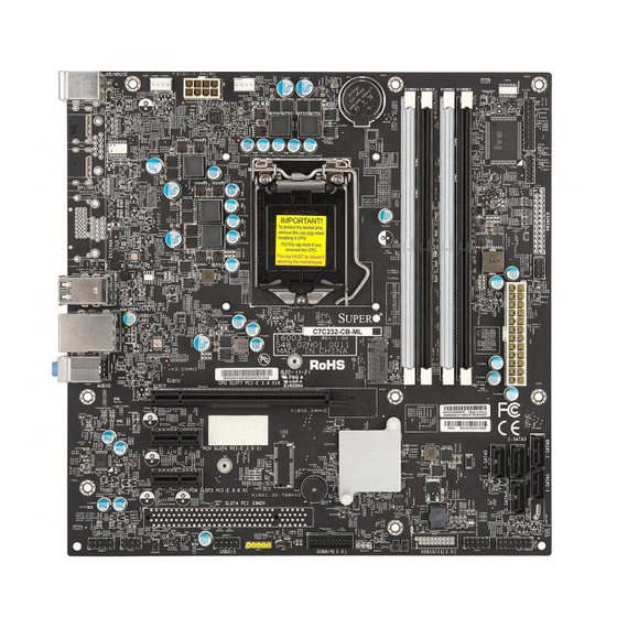
• Product safety info: http://www.supermicro.com/about/policies/safety_information.cfm • If you have any questions, please contact our support team at: support@supermicro.com This manual may be periodically updated without notice. Please check the Supermicro website for possible updates to the manual revision level. - Page 9 Chapter 1: Introduction Figure 1-1. C7C232-CB-ML Motherboard Image Note: All graphics shown in this manual were based upon the latest PCB revision available at the time of publication of the manual. The motherboard you received may or may not look exactly the same as the graphics shown in this manual.
- Page 10 C7C232-CB-ML User's Manual Figure 1-2. C7C232-CB-ML Motherboard Layout (not drawn to scale) KB/MOUSE AUDIO USB4/5/6/7 USB0/1 (3.0) LAN1 FANS1 FANS2 C7C232-CB-ML OBR1 Rev. 1.00 FANC1 BUZ1 NGFFB1 GPIO1 DIMMA1 DIMMA2 DIMMB1 DIMMB2 I-SATA5 I-SATA4 I-SATA3 TPMH1 DBGH1 I-SATA0 I-SATA1 PCHDR1...
-
Page 11: Quick Reference
USB4/5/6/7 KB/MOUSE (3.0) SLOT7 SLOT6 SLOT5 AUDF1 KB/MOUSE AUDIO USB4/5/6/7 USB0/1 (3.0) SPK1 LAN1 CSOPN1 FANS1 FANS1 FANS2 FANS2 C7C232-CB-ML OBR1 OBR1 Rev. 1.00 USB2/3 FANC1 FANC1 CRF1 BUZ1 USB8/9 BUZ1 (3.0) CMOS1 NGFFB1 GPIO2 GPIO1 DIMMA1 GPIO1 DIMMA1 DIMMA2... -
Page 12: Quick Reference Table
C7C232-CB-ML User's Manual Quick Reference Table Jumper Description Default Setting CMOS1 CMOS Clear Pins 1-2 (Normal), Pins 2-3 (Clear CMOS) BIOS Write Protect Header Pins 2-3 (Enable) Connector Description AUDF1 Front Panel Audio Header AUDIO Back Panel Audio Port Onboard Battery... -
Page 13: Motherboard Features
Chapter 1: Introduction Motherboard Features Motherboard Features • Intel® Xeon E3-1200 V5 processor and Intel 6th Generation Core i3/i5/i7 processor in an LGA1151 socket. Memory • Up to 64GB of DDR4 Non-ECC UDIMM 2133MHz memory, two DIMMs per channel. DIMM Size •... - Page 14 • Power-on mode for AC power recovery • Intel® Intelligent Power Node Manager 3.0 (available when the Supermicro Power Manager [SPM] is installed and a special power supply is used. See the note on page 22.) • Management Engine (ME) System Health Monitoring •...
- Page 15 User's Guide available at http://www.supermicro.com/support/manuals/. Note 3: It is strongly recommended that you change BMC login information upon initial system power-on. The manufacture default username is ADMIN and the password is ADMIN. For proper BMC configuration, please refer to http://www.supermicro.com/ products/info/files/IPMI/Best_Practices_BMC_Security.pdf...
-
Page 16: System Block Diagram
C7C232-CB-ML User's Manual Figure 1-3. System Block Diagram DDR4 CHA DDR4 DIMM *1 Intel PCIE 3.0 PCIEx16 slot DDR4 DIMM *1 DDR4 CHB E3-1200 V5 PCIE3.0 RJ45 CONN/ USB 3.0 Intel LAN I219V Front USB 3.0 *2 USB2.0 x2 stack USB 2.0... -
Page 17: Processor And Chipset Overview
Built upon the functionality and capability of the Intel E3-1200 V5 series processors (Socket LGA 1151) and the Intel C232 PCH, the C7C232-CB-ML motherboard offers maximum I/O expandability, energy efficiency, and data reliability in a 14-nm process architecture and is optimized for desktop solutions. -
Page 18: System Health Monitoring
C7C232-CB-ML User's Manual 1.4 System Health Monitoring This section describes the health monitoring features of the C7C232-CB-ML motherboard. The motherboard has an onboard Baseboard Management Controller (BMC) chip that supports system health monitoring. Once a voltage becomes unstable, a warning is given or an error message is sent to the screen. -
Page 19: Acpi Features
Chapter 1: Introduction 1.5 ACPI Features ACPI stands for Advanced Configuration and Power Interface. The ACPI specification defines a flexible and abstract hardware interface that provides a standard way to integrate power management features throughout a computer system including its hardware, operating system and application software. -
Page 20: Advanced Power Management
Intelligent Power Node Manager (IPNM) ® Available when the Supermicro Power Manager (SPM) is installed, Intel's Intelligent Power Node Manager (IPNM) provides your system with real-time thermal control and power management for maximum energy efficiency. Although IPNM Specification Version 2.0/3.0 is supported by the BMC (Baseboard Management Controller), your system must also have IPNM-compatible Management Engine (ME) firmware installed to use this feature. -
Page 21: Chapter 2 Installation
Chapter 2: Installation Chapter 2 Installation 2.1 Static-Sensitive Devices Electrostatic Discharge (ESD) can damage electronic com ponents. To prevent damage to your motherboard, it is important to handle it very carefully. The following measures are generally sufficient to protect your equipment from ESD. Precautions •... -
Page 22: Motherboard Installation
C7C232-CB-ML User's Manual 2.2 Motherboard Installation All motherboards have standard mounting holes to fit different types of chassis. Make sure that the locations of all the mounting holes for both the motherboard and the chassis match. Although a chassis may have both plastic and metal mounting fasteners, metal ones are highly recommended because they ground the motherboard to the chassis. -
Page 23: Installing The Motherboard
Chapter 2: Installation Installing the Motherboard 1. Install the I/O shield into the back of the chassis. 2. Locate the mounting holes on the motherboard. See the previous page for the location. 3. Locate the matching mounting holes on the chassis. Align the mounting holes on the motherboard against the mounting holes on the chassis. -
Page 24: Processor And Heatsink Installation
CPU socket cap is in place and none of the socket pins are bent; otherwise, contact your retailer immediately. • Refer to the Supermicro website for updates on CPU support. Installing the LGA1151 Processor 1. Press the load lever to release the load plate, which covers the CPU socket, from its locking position. - Page 25 Chapter 2: Installation 2. Gently lift the load lever to open the load plate. Remove the plastic cap. 3. Use your thumb and your index finger to hold the CPU at the north center edge and the South center edge of the CPU. North Center Edge South Center Edge 4.
- Page 26 C7C232-CB-ML User's Manual 5. Do not rub the CPU against the surface or against any pins of the socket to avoid damaging the CPU or the socket. 6. With the CPU inside the socket, inspect the four corners of the CPU to make sure that the CPU is properly installed.
-
Page 27: Installing An Active Cpu Heatsink With Fan
Chapter 2: Installation Installing an Active CPU Heatsink with Fan 1. Locate the CPU fan power connector on the motherboard. (Refer to the layout on Thermal Grease the right for the CPU Fan location.) 2. Position the heatsink so that the heatsink fan wires are closest to the CPU fan power connector and are not interfered with other components. - Page 28 C7C232-CB-ML User's Manual 7. Align the four heatsink fasteners with the mounting holes on the motherboard. Gently push the pairs of diagonal fasteners (#1 & #2, and #3 & #4) into the mounting holes until you hear a click. Also, make sure to orient each fastener so that the narrow end of the groove is pointing outward.
-
Page 29: Removing The Heatsink
Chapter 2: Installation Removing the Heatsink Note: We do not recommend that the CPU or the heatsink be removed. However, if you do need to remove the heatsink, please follow the instructions below to remove the heatsink and to prevent damage done to the CPU or other components. -
Page 30: Memory Support And Installation
Memory Support The C7C232-CB-ML supports up to 32GB of DDR4 Non-ECC UDIMM 2133MHz memory. Populating these DIMM modules with a pair of memory modules of the same type and size will result in interleaved memory, which will improve memory performance. -
Page 31: Dimm Installation
1. Insert DIMM modules in the following USB4/5/6/7 USB0/1 (3.0) LAN1 FANS1 order: DIMMB2, DIMMA2, then DIMMB1, FANS2 C7C232-CB-ML OBR1 Rev. 1.00 DIMMA1. For the system to work properly, FANC1 please use memory modules of the same type and speed on the motherboard. BUZ1 2. -
Page 32: Rear I/O Ports
C7C232-CB-ML User's Manual 2.5 Rear I/O Ports See Figure 2-2 below for the locations and descriptions of the various I/O ports on the rear of the motherboard. KB/MOUSE AUDIO USB4/5/6/7 USB0/1 (3.0) LAN1 FANS1 FANS2 C7C232-CB-ML OBR1 Rev. 1.00 FANC1... - Page 33 Serial Port There is one COM header (COM1) on the motherboard to provide front side access. 1. LAN1 2. COM1 KB/MOUSE AUDIO USB4/5/6/7 USB0/1 (3.0) LAN1 FANS1 FANS2 C7C232-CB-ML OBR1 Rev. 1.00 FANC1 BUZ1 NGFFB1 GPIO1 DIMMA1 DIMMA2 DIMMB1 DIMMB2 I-SATA5...
- Page 34 C7C232-CB-ML User's Manual KB/MOUSE The PS2 keyboard and mouse ports are located on the I/O back panel. KB/MOUSE Pin Definitions Keyboard Mouse Defintion Defintion KB Data Mouse Data No Connection No Connection Ground Ground Mouse/KB VCC Mouse/KB VCC (+5V) (+5V)
- Page 35 USB_RX_CON_P2 USB_CON_PN5 USB_RX_CON_N2 USB_CON_PP5 5V_USB30H1 1. USB0/1 2. USB4/5/6/7 KB/MOUSE AUDIO USB4/5/6/7 USB0/1 (3.0) 3. USB2/3 LAN1 FANS1 FANS2 4. USB8/9 C7C232-CB-ML OBR1 Rev. 1.00 FANC1 BUZ1 NGFFB1 GPIO1 DIMMA1 DIMMA2 DIMMB1 DIMMB2 I-SATA5 I-SATA4 I-SATA3 DBGH1 TPMH1 I-SATA1 I-SATA0...
-
Page 36: Connectors
C7C232-CB-ML User's Manual 2.6 Connectors Power Connections Main ATX Power Supply Connector The primary power supply connector (CN1) meets the ATX SSI EPS 24-pin specification. You must also connect the 8-pin (CN2) processor power connector to your power supply. ATX Power 24-pin Connector... - Page 37 Pin# Definition 1 - 4 Ground 5 - 8 +12V Required Connection 1. 8-Pin PWR KB/MOUSE AUDIO USB4/5/6/7 USB0/1 (3.0) LAN1 FANS1 FANS2 C7C232-CB-ML OBR1 Rev. 1.00 FANC1 BUZ1 NGFFB1 GPIO1 DIMMA1 DIMMA2 DIMMB1 DIMMB2 I-SATA5 I-SATA4 I-SATA3 DBGH1 TPMH1...
-
Page 38: Front Control Panel
LEDH1 contains header pins for various buttons and indicators that are normally located on a control panel at the front of the chassis. These connectors are designed specifically for use with Supermicro chassis. See the figure below for the descriptions of the front control panel buttons and LED indicators. - Page 39 Chapter 2: Installation Power Button The Power Button connection is located on pins 5 and 6. Attach it to a power switch on the computer case to power on the system. Power Button Pin Definitions Pins Definition Ground PWR BTN FP Reset Button The Reset Button connection is located on pins 7 and 8.
- Page 40 C7C232-CB-ML User's Manual Power LED The Power LED connection is located on pins 2 and 4. Power LED Pin Definitions Pins Definition PWR LED (+) PWR LED (-) HD LED PWR/SATA LED The SATA LED connection is located on pins 1 and 3. Attach a cable here to indicate the status of SATA-related activities.
-
Page 41: Headers
MONO_L AUDIO_GROUND MONO_R AUDIO_GROUND AUDIO_GROUND MUTE_C 1. FANC1 2. FANS1 KB/MOUSE AUDIO USB4/5/6/7 USB0/1 (3.0) LAN1 3. Speaker Header FANS1 FANS2 C7C232-CB-ML OBR1 Rev. 1.00 FANC1 BUZ1 NGFFB1 DIMMA1 GPIO1 DIMMA2 DIMMB1 DIMMB2 I-SATA5 I-SATA4 I-SATA3 DBGH1 TPMH1 I-SATA1 I-SATA0... - Page 42 C7C232-CB-ML User's Manual Front Panel Audio Header A 10-pin audio header at AUDF1 allows you to use the onboard sound for audio playback. Connect an audio cable to the audio header to use this feature. See the table below pin definitions.
- Page 43 PL_TRST#_PCH LPC_AD3 LPC_AD2 3.3VS) LPC_AD1 LPC_AD0 P3V3_S5 LPC_SERIRQ_PCH SUS_STAT-N 1. TPM Header KB/MOUSE AUDIO USB4/5/6/7 USB0/1 (3.0) LAN1 FANS1 FANS2 C7C232-CB-ML OBR1 Rev. 1.00 FANC1 BUZ1 NGFFB1 GPIO1 DIMMA1 DIMMA2 DIMMB1 DIMMB2 I-SATA5 I-SATA4 I-SATA3 DBGH1 TPMH1 I-SATA1 I-SATA0 PCHDR1...
- Page 44 C7C232-CB-ML User's Manual PC Health Header PC health header at PCHDR1 monitors the power supply, fan and system temperatures. See the table below for pin definitions. PC Health Header Pin Definitions Pin# Definition Pin# Definition 5V_S0 3D3V_S0 SMB_CLK_PCHD PLTRST#_PCH SMB_DATA_PCHD...
- Page 45 Chapter 2: Installation SATA and SAS Ports The C7C232-CB-ML has five SATA 3.0 ports that are supported by the Intel PCH C232 chipset. M.2 Slot The M.2 slot at NGFFB1 is designed for internal mounting devices. The C7C232-CB-ML motherboard deploys an M key only dedicated for SSD devices with the ulitmate performance capability in a PCI Express 3.0 X4 interface for native PCI-E SSD support.
- Page 46 C7C232-CB-ML User's Manual Internal Speaker/Buzzer The Internal Speaker/Buzzer at BUZ1 is used to provide audible indications for various beep codes. See the table below for pin definitions. Internal Buzzer Pin Definitions Pin# Definition Pos (+) Beep In Neg (-) Alarm Speaker Front Accessible USB 2.0 Header...
-
Page 47: Jumper Settings
System Recovery Jumper Settings Jumper Setting Definition Open Normal Closed System recovery 1. System Recovery KB/MOUSE AUDIO USB4/5/6/7 USB0/1 (3.0) LAN1 FANS1 FANS2 C7C232-CB-ML OBR1 Rev. 1.00 FANC1 BUZ1 NGFFB1 GPIO1 DIMMA1 DIMMA2 DIMMB1 DIMMB2 I-SATA5 I-SATA4 I-SATA3 DBGH1 TPMH1 I-SATA1... - Page 48 C7C232-CB-ML User's Manual CMOS Clear CMOS1 is used to clear CMOS, which will also clear any passwords. CMOS Clear Jumper Settings Jumper Setting Definition Pins 1-2 Normal Pins 2-3 Clear CMOS Write Protect Header WP1 allows you to enable or disable the SPI Flash ROM write protection.
-
Page 49: Chapter 3 Troubleshooting
Chapter 3: Troubleshooting Chapter 3 Troubleshooting 3.1 Troubleshooting Procedures Use the following procedures to troubleshoot your system. If you have followed all of the procedures below and still need assistance, refer to the ‘Technical Support Procedures’ and/ or ‘Returning Merchandise for Service’ section(s) in this chapter. Always disconnect the AC power cord before adding, changing or installing any non hot-swap hardware components. -
Page 50: No Video
C7C232-CB-ML User's Manual No Video 1. If the power is on but you have no video, remove all the add-on cards and cables. 2. Use the speaker to determine if any beep codes exist. Refer to Appendix A for details on beep codes. -
Page 51: Losing The System's Setup Configuration
2. Memory support: Make sure that the memory modules are supported by testing the modules using memtest86 or a similar utility. Note: Refer to the product page on our website at http:\\www.supermicro.com for memory and CPU support and updates. 3. HDD support: Make sure that all hard disk drives (HDDs) work properly. Replace the bad HDDs with good ones. - Page 52 C7C232-CB-ML User's Manual 3. Using the minimum configuration for troubleshooting: Remove all unnecessary components (starting with add-on cards first), and use the minimum configuration (but with a CPU and a memory module installed) to identify the trouble areas. Refer to the steps listed in Section A above for proper troubleshooting procedures.
-
Page 53: Technical Support Procedures
Chapter 3: Troubleshooting 3.2 Technical Support Procedures Before contacting Technical Support, please take the following steps. Also, note that as a motherboard manufacturer, we do not sell directly to end-users, so it is best to first check with your distributor or reseller for troubleshooting services. They should know of any possible problem(s) with the specific system configuration that was sold to you. -
Page 54: Frequently Asked Questions
Updated BIOS files are located on our website at http://www. supermicro.com. Please check our BIOS warning message and the information on how to update your BIOS on our website. Select your motherboard model and download the BIOS file to your computer. -
Page 55: Battery Removal And Installation
Chapter 3: Troubleshooting 3.4 Battery Removal and Installation Battery Removal To remove the onboard battery, follow the steps below: 1. Power off your system and unplug your power cable. 2. Locate the onboard battery as shown below. 3. Using a tool such as a pen or a small screwdriver, push the battery lock outwards to unlock it. -
Page 56: Returning Merchandise For Service
C7C232-CB-ML User's Manual 3.5 Returning Merchandise for Service A receipt or copy of your invoice marked with the date of purchase is required before any warranty service will be rendered. You can obtain service by calling your vendor for a Returned Merchandise Authorization (RMA) number. -
Page 57: Chapter 4 Bios
BIOS 4.1 Introduction This chapter describes the AMIBIOS™ Setup utility for the C7C232-CB-ML motherboards. The BIOS is stored on a chip and can be easily upgraded using a flash program. Note: Due to periodic changes to the BIOS, some settings may have been added or deleted and might not yet be recorded in this manual. -
Page 58: Main Setup
C7C232-CB-ML User's Manual 4.2 Main Setup When you first enter the AMI BIOS setup utility, you will enter the Main setup screen. You can always return to the Main setup screen by selecting the Main tab on the top of the screen. - Page 59 Chapter 4: BIOS Processor Information Name This item displays the processor type. Brand String This item displays the processor version and speed. Frequency This item displays the processor freqency. Processor ID This item displays the processor ID number. Stepping This item displays the processor stepping information. Number of Processors This item displays the number or processor Core and thread.
- Page 60 C7C232-CB-ML User's Manual ME Firmware Revision This item displays the Management Engine firmware revision. ME Firmware SKU This item displays the Management Engine firmware SKU. System Language This item displays the language. System Date This item displays the system date System Time This item displays the system time.
-
Page 61: Advanced Setup Configurations
Chapter 4: BIOS 4.3 Advanced Setup Configurations Use the arrow keys to select Advanced setup and press <Enter> to access the submenu items: Warning: Take Caution when changing the Advanced settings. An incorrect value, a very high DRAM frequency or an incorrect BIOS timing setting may cause the system to malfunction. When this occurs, restore the setting to the manufacture default setting. -
Page 62: Acpi Settings
C7C232-CB-ML User's Manual TPM State This feature changes the TPM State. The options are Disabled and Enabled. Note: The system will restart to change the TPM State. Pending operation Use this item to schedule a TPM-related operation to be performed by a security device for system data integrity. -
Page 63: Amt Configuration
Chapter 4: BIOS ACPI Low Power S0 Idle Enable this feature for hardware components that are not in use to enter a low power state. The options are Disabled and Enabled. Intel ICC (Integrated Clock Control) ICC/OC Watchdog Timer If Enabled, the ICC Watchdog Timer will be exposed to the operating system as an ACPI device. - Page 64 C7C232-CB-ML User's Manual MEBx Debug Message Output Use this feature to enable or disable MEBx debug message output. The options are Disabled and Enabled. Un-Configure ME Use this feature to enable or disable unconfigure ME without password. The options are Disabled and Enabled.
-
Page 65: Firmware Update Configuration
Chapter 4: BIOS OverClocking Performance Menu OverClocking Feature Use this feature to enable or disable processor and memory overclocking. The options are Disabled and Enabled. Use this feature to enable or disable the Reliability Stress Restricter (RSR) feature. The options are Disabled and Enabled. -
Page 66: Smart Settings
C7C232-CB-ML User's Manual ASF WatchDog Timer Use this feature to disable or enable the Watch Dog timer. The options are Disabled and Enabled. The following information will display: • WatchDog Timer: BIOS • WatchDog Timer: OS SMART Settings SMART Self Test Enable this feature to allow Self Monitoring Analysis and Reporting Technology (SMART) self test on all hard disk drives during POST. -
Page 67: Cpu Configuration
Chapter 4: BIOS Intel® Bios Guard Technology Intel Bios Guard Support Select Enabled to prevent unauthorized software access and to add hardware protection. The options are Disabled and Enabled. CPU Configuration The following CPU information will display: • CPU Type •... - Page 68 C7C232-CB-ML User's Manual • L2 Cache • L3 Cache • L4 Cache Hyper-threading (Available when supported by the CPU) Select Enabled to support Intel Hyper-threading Technology to enhance CPU performance. The options are Enabled and Disabled. Active Processor Cores This feature determines how many CPU cores will be activated for each CPU. When all is selected, all cores in the CPU will be activated.
- Page 69 Chapter 4: BIOS Power Limit 1 Override Select Enabled to support average power limit (PL1) override. The default setting is Disabled. *If the item above is set to Enabled, the next two items will be available for user configuration: Power Limit 1 Use this item to configure the value for Power Limit 1.
- Page 70 C7C232-CB-ML User's Manual CPU C states Use this feature to enable the C-State of the CPU. The options are Disabled and Enabled. Enhanced C-states Use this feature to enable the enhanced C-State of the CPU. The options are Disabled and Enabled.
- Page 71 Chapter 4: BIOS ACPI 3.0 T-States Select Enabled to support CPU throttling by the operating system to reduce power consumption. The options are Enabled and Disabled. Intel TXT (LT) Support Intel TXT (Trusted Execution Technology) helps protect against software-based attacks and ensures protection, confidentiality and integrity of data stored or created on the system.
-
Page 72: Platform Misc Configuration
C7C232-CB-ML User's Manual Intel TXT Information The following Intel TXT information will display: • Chipset • BiosAcm • Chipset Txt • Cpu Txt • Error Code • Class Code • Major Code • Minor Code Platform Misc Configuration ... -
Page 73: Sata Configuration
Chapter 4: BIOS Enable Wireless Charge Support Use this feature to enable or disable wireless charging support. The options are Disabled and Enabled. Enable FFU Support Use this feature to enable or disable FFU (Full Flash Update) support. FFU can capture hard drive information, including partitions. - Page 74 C7C232-CB-ML User's Manual OROM UI and Banner Select Enabled for RAID information to display during the POST. The options are Disabled and Enabled. HDD Unlock Select Enabled to enable the HDD password unlock. The options are Disabled and Enabled. LED Locate If Enabled, this feature provides an indication that the LED/SGPIO hardware is attached.
-
Page 75: Thermal Configuration
Chapter 4: BIOS Hot Plug This feature designates the SATA port specified for hot plugging. Set this item to Enabled for hot-plugging support, which will allow the user to replace a SATA disk drive without shutting down the system. The options are Disabled and Enabled. External SATA Use this feature to disable or enable external SATA support. -
Page 76: Acoustic Management Configuration
C7C232-CB-ML User's Manual Active Trip Point 0 Fan Speed Use this feature to set the fan speed in percentage. The value is from 0 to 100. Use the "+" or "-" keys to set the value. Active Trip Point 1 Use this feature to set the temperature of the ACPI Active Trip Point 1 that turns on the processor fan. -
Page 77: Network Stack Configuration
Chapter 4: BIOS Network Stack Configuration Network Stack Select Enabled to enable UEFI (Unified Extensible Firmware Interface) for network stack support. The options are Disabled and Enabled. *If Network Stack is Enabled, the four items below are available for configuration: IPv4 PXE Support Select Enabled to enable IPv4 PXE boot support. -
Page 78: Sdio Configuration
C7C232-CB-ML User's Manual Boot option filter This option prioritizes the order of bootable devices that the system to boot from. The options are UEFI and Legacy, Legacy only, and UEFI only. Option ROM execution Network Use this item to select the network Option ROM type. The options are Do Not Launch, UEFI, and Legacy. - Page 79 Chapter 4: BIOS Legacy USB Support This feature enables support for legacy USB devices. Select Auto to disable legacy support if USB devices are not present. Select Disable to have USB devices available only for EFI applications. The options are Enabled, Disabled, and Auto. XHCI Hand-off This is a work-around solution for operating systems that do not support XHCI (Extensible Host Controller Interface) hand-off.
-
Page 80: Chipset
C7C232-CB-ML User's Manual 4.4 Chipset Use this feature to configure Chipset settings. System Agent (SA) Configuration The following System Agent information will display: • System Agent Bridge Name • SA PCIe Code Version • VT-d VT-d Select Enabled to enable Intel Virtualization Technology support for Direct I/O VT-d by reporting the I/O device assignments to VMM through the DMAR ACPI Tables. -
Page 81: Graphics Configuration
Chapter 4: BIOS Graphics Configuration Primary Display Use this feature to select the graphics device to be used as the primary display. The options are Auto, PEG, and PCIE. Primary PEG This feature allows the user to select the primary PCI Express Graphics (PEG) slot. The options are Auto, PEG11, and PEG12. - Page 82 C7C232-CB-ML User's Manual DMI De-emphasis Control Use this feature to configure the De-emphasis control on DMI. The options are -6 dB and -3.5 dB. PEG Port Configuration PEG 0:1:0 Enable Root Port Use this feature to enable or disable the PCI Express Graphics (PEG) device in the port specified by the user.
-
Page 83: Memory Configuration
Chapter 4: BIOS PEG1 Slot Power Limit Scale Use this feature to select the scale used for the slot power limit value. The options are 1.0x, 0.1x, 0.01x, and 0.001x. PEG 0:1:2 Enable Root Port Use this feature to enable or disable the PCI Express Graphics (PEG) device in the port specified by the user. - Page 84 C7C232-CB-ML User's Manual • Total Memory • • DIMMA1 • DIMMA2 • DIMMB1 • DIMMB2 • Memory Timings (tCL-tRCD-tRP-tRAS) Maximum Memory Frequency Use this feature to set the maximum memory frequency for onboard memory modules. The options are Auto, 1067, 1333, 1600, 1867, 2133, 2400, 2667, 2933, and 3200.
- Page 85 Chapter 4: BIOS Force Single Rank Set this feature to Enabled for Rank 0 to be used for each DIMM module. The options are Disabled and Enabled. Time Measure Use this feature to enable or disable the printing of the time it takes to execute the memory reference code (MRC).
- Page 86 C7C232-CB-ML User's Manual • Write Energy DIMMA2 • Idle Energy DIMMB1 • PowerDown Energy DIMMB1 • Activate Energy DIMMB1 • Read Energy DIMMB1 • Write Energy DIMMB1 • Idle Energy DIMMB2 • PowerDown Energy DIMMB2 • Activate Energy DIMMB2 •...
-
Page 87: Pci Express Configuration
Chapter 4: BIOS PCH-IO Configuration The following PCH-IO information will display: • Intel PCH RC Version • Intel PCH SKU Name • Intel PCH Rev ID PCI Express Configuration DMI Link ASPM Control Use this feature to set the ASPM (Active State Power Management) state on the SA (System Agent) side of the DMI Link. - Page 88 C7C232-CB-ML User's Manual PCIE LTR Use this feature to enable or disable PCIE latency reporting. The options are Disabled and Enabled. USB Configuration USB SS Physical Connector #0 ~ #9 Use this feature to enable or disable the designated USB SuperSpeed port. The options are Disabled or Enabled.
- Page 89 Chapter 4: BIOS I/O Buffer Voltage Select Use this feature to select the voltage for the I/O buffer. The options are 3.3V and 1.8V. HD Audio Link Frequency Use this feature to select the HD audio link frequency. The options are 6 MHz, 12 MHZ, and 24 MHz.
- Page 90 C7C232-CB-ML User's Manual DeepSx Power Policies Use this item to configure the Advanced Configuration and Power Interface (ACPI) settings for the system. Enable S3 to use Standby Mode (Suspend-to-RAM) and maintain power supply to the system RAM when the system is in the sleep mode. Enable S4 to use Hibernation mode (Suspend to Disk) so that all data stored in of the main memory can be saved in a non-volatile memory area such as in a hard drive and then power down the system.
-
Page 91: Security
Chapter 4: BIOS 4.5 Security This menu allows the user to configure the following security settings for the system. Administrator Password Use this feature to set the administrator password which is required to enter the BIOS setup utility. The length of the password should be from 3 characters to 20 characters long. User Password Press Enter to create a new or change an existing User password. - Page 92 C7C232-CB-ML User's Manual Secure Boot Mode Use this item to select the secure boot mode. The options are Standard and Custom. Key Management This submenu allows the user to configure the following Key Management settings. Provision Factory Default Keys Select Enabled to install the default Secure-Boot keys set by the manufacturer.
- Page 93 Chapter 4: BIOS Forbidden Signatures Set New Key Select Yes to load the DBX from the manufacturer's defaults. Select No to load the DBX from a file. The options are Yes and No. Append Key Select Yes to add the DBX from the manufacturer's defaults to the existing DBX. Select No to load the DBX from a file.
-
Page 94: Boot
C7C232-CB-ML User's Manual 4.6 Boot Use this feature to configure Boot Settings: Setup Prompt Timeout Use this item to indicate the length of time (the number of seconds) for the BIOS to wait before rebooting the system when the setup activation key is pressed. Enter the value of 65535 (0xFFFF) for the BIOS to wait indefinitely. -
Page 95: Save & Exit
Chapter 4: BIOS 4.7 Save & Exit Select the Save & Exit tab from the BIOS setup screen to configure the settings below. Save Options Save Changes and Exit When you have completed the system configuration changes, select this option to save all changes made and exit. - Page 96 C7C232-CB-ML User's Manual Save Changes After completing the system configuration changes, select this option to save the changes you have made. This will not reset (reboot) the system. Discard Changes Select this option and press <Enter> to discard all the changes and return to the AMI BIOS utility Program.
-
Page 97: Appendix A Bios Codes
Appendix A: BIOS Codes Appendix A BIOS Codes A.1 BIOS Error POST (Beep) Codes During the POST (Power-On Self-Test) routines, which are performed each time the system is powered on, errors may occur. Non-fatal errors are those which, in most cases, allow the system to continue the boot-up process. - Page 98 When BIOS performs the Power On Self Test, it writes checkpoint codes to I/O port 0080h. If the computer cannot complete the boot process, a diagnostic card can be attached to the computer to read I/O port 0080h (Supermicro p/n AOC-LPC80-20). For information on AMI updates, please refer to http://www.ami.com/products/.
-
Page 99: Appendix B Software Installation
Appendix B Software Installation B.1 Installing Software Programs The Supermicro FTP site contains drivers and utilities for your system at ftp://ftp.supermicro. com. Some of these must be installed, such as the chipset driver. After accessing the FTP site, go into the CDR_Images directory and locate the ISO file for your motherboard. -
Page 100: Superdoctor ® 5
SATA settings back to your original settings. B.2 SuperDoctor ® The Supermicro SuperDoctor 5 is a hardware monitoring program that functions in a command-line or web-based interface in Windows and Linux operating systems. The program monitors system health information such as CPU temperature, system voltages, system power consumption, fan speed, and provides alerts via email or Simple Network Management Protocol (SNMP). -
Page 101: Appendix C Standardized Warning Statements
The following statements are industry standard warnings, provided to warn the user of situations which have the potential for bodily injury. Should you have questions or experience difficulty, contact Supermicro's Technical Support department for assistance. Only certified technicians should attempt to install or configure components. - Page 102 C7C232-CB-ML User's Manual Attention Danger d'explosion si la pile n'est pas remplacée correctement. Ne la remplacer que par une pile de type semblable ou équivalent, recommandée par le fabricant. Jeter les piles usagées conformément aux instructions du fabricant. ¡Advertencia! Existe peligro de explosión si la batería se reemplaza de manera incorrecta. Reemplazar la batería exclusivamente con el mismo tipo o el equivalente recomendado por el fabricante.
-
Page 103: Product Disposal
Appendix C: Warning Statements Product Disposal Warning! Ultimate disposal of this product should be handled according to all national laws and regulations. 製品の廃棄 この製品を廃棄処分する場合、 国の関係する全ての法律 ・ 条例に従い処理する必要があります。 警告 本产品的废弃处理应根据所有国家的法律和规章进行。 警告 本產品的廢棄處理應根據所有國家的法律和規章進行。 Warnung Die Entsorgung dieses Produkts sollte gemäß allen Bestimmungen und Gesetzen des Landes erfolgen. -
Page 104: Appendix D Uefi Bios Recovery
Warning: Do not upgrade the BIOS unless your system has a BIOS-related issue. Flashing the wrong BIOS can cause irreparable damage to the system. In no event shall Supermicro be liable for direct, indirect, special, incidental, or consequential damages arising from a BIOS update. - Page 105 1. Using a different system, copy the "Super.ROM" binary image file into the disc Root "\" Directory of a USB device or a writeable CD/DVD. Note: If you cannot locate the "Super.ROM" file in your driver disk, visit our website www.supermicro.com to download the BIOS image into a USB flash device and rename it "Super.ROM".
- Page 106 C7C232-CB-ML User's Manual 4. After locating the new BIOS binary image, the system will enter the BIOS Recovery menu as shown below. Note: At this point, you may decide if you want to start the BIOS recovery. If you decide to proceed with BIOS recovery, follow the procedures below.
- Page 107 Appendix D: UEFI BIOS Recovery 6. After the BIOS recovery process has completed, press any key to reboot the system. 7. Using a different system, extract the BIOS package into a bootable USB flash drive. 8. When a DOS prompt appears, enter FLASH.BAT BIOSname.### at the prompt. Note: Do not interrupt this process until the BIOS flashing is complete.