Sony TRINITRON PVM-8042Q Service Manual
S mic chassis color video monitor
Hide thumbs
Also See for TRINITRON PVM-8042Q:
- Brochure & specs (7 pages) ,
- Catalog (46 pages) ,
- Operating instructions manual (36 pages)
Table of Contents
Advertisement
SERVICE MANUAL
MODEL
...............
PVM-8042Q
PVM-8045Q
DEST.
CHASSIS NO.
.........
.....................
US/CND
SCC-E96H-A
US/CND
SCC-E96J-A
MIC
S
MODEL
...............
PVM-9042QM
PVM-9042QM
PVM-9045QM
PVM-9045QM
PVM-9045PM
TRINITRON
COLOR VIDEO MONITOR
®
CHASSIS
DEST.
CHASSIS NO.
.........
.....................
AEP
SCC-F09H-A
AUS
SCC-F90F-A
AEP
SCC-F09J-A
AUS
SCC-F90G-A
BRZ
SCC-F31B-A
Advertisement
Table of Contents

Related Manuals for Sony TRINITRON PVM-8042Q


Summary of Contents for Sony TRINITRON PVM-8042Q
-
Page 1: Service Manual
SERVICE MANUAL CHASSIS MODEL MODEL DEST. CHASSIS NO. DEST. CHASSIS NO. …………… ……… ………………… …………… ……… ………………… PVM-8042Q PVM-9042QM US/CND SCC-E96H-A SCC-F09H-A PVM-8045Q PVM-9042QM US/CND SCC-E96J-A SCC-F90F-A PVM-9045QM SCC-F09J-A PVM-9045QM SCC-F90G-A PVM-9045PM SCC-F31B-A TRINITRON COLOR VIDEO MONITOR ®... - Page 2 PUBLISHED BY SONY. CIRCUIT ADJUSTMENTS THAT ARE FONCTIONNEMENT. NE LES REMPLACER QUE PAR DES CRITICAL TO SAFE OPERATION ARE IDENTIFIED IN THIS COMPOSANTS SONY DONT LE NUMÉRO DE PIÉCE EST INDIQUÉ MANUAL. FOLLOW THESE PROCEDURES WHENEVER CRITICAL DANS LE PRÉSENT MANUEL OU DANS DES SUPPLÉMENTS COMPONENTS ARE REPLACED OR IMPROPER OPERATION IS PUBLIÉS PAR SONY.
-
Page 3: Table Of Contents
TABLE OF CONTENTS 1. OPERATING INSTRUCTIONS 2. SERVICE INFORMATION 2-1. CIRCUIT BOARDS LOCATION ..............2-1 2-2. DISASSEMBLY .................... 2-2 2-2-1. Cabinet Removal ..................2-2 2-2-2. B Board Removal ................... 2-2 2-2-3. Switching Regulator Removal ..............2-3 2-2-4. D Board Removal ................... 2-3 2-2-5. - Page 4 5. CIRCUIT ADJUSTMENTS 5-1. D BOARD ADJUSTMENTS ................. 5-1 5-1-1. Horizontal Oscillating Frequency Adjustment (RV503) ......5-1 5-1-2. Video Phase Adjustment (RV512, RV516, RV502) ......5-1 5-1-3. Vertical Blanking Adjustment (RV501) ..........5-2 5-1-4. Horizontal Blanking Adjustment (RV516) ..........5-2 5-1-5.
- Page 5 9. BLOCK DIAGRAMS (1/2) ........................ 9-1 A ..............................X ........................... 9-1 B ........................... 9-2 S ........................... 9-4 (2/2) ........................ 9-4 A ............................... G ........................... 9-4 D ........................... 9-5 A ............................... P ........................... 9-6 A ............................... 10. DIAGRAMS 10-1. FRAME SCHEMATIC DIAGRAMS ............10-2 10-2.
- Page 7 3-865-058-11 (1) Trinitron ® Color Video Monitor Operating Instructions Mode d’emploi Manual de instrucciones PVM-8045Q PVM-8042Q PVM-8040 © 1998 by Sony Corporation (EN)
- Page 8 Retain the original carton and packing materials for expressly approved in this manual could void your authority safe transport of this unit in the future. to operate this equipment. If you have any questions about this unit, contact your authorized Sony dealer. (US) (US)
- Page 9 In addition to AC power, you can use battery pack or external sync connector. external DC 12 V power. The monitor can operate with one or two Sony NP-1B* battery packs. If you use the Blue only picture (PVM-8045Q/8042Q only) DC-L10* battery adaptor, the monitor can operate with Black and white apparent picture consisting from only a Sony BP-L60A/L90A* lithium ion battery pack.
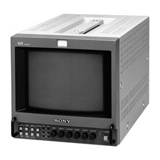
- Page 10 Location and Function of Parts and Controls Front PVM-8040 PVM-8045Q/8042Q 1 Tally lamp 9 DEGAUSS button !º SYNC INT/EXT (sync internal/external) selector !¡ LINE/RGB input selector 2 POWER switch and indicator !™ A/B, RGB/Y R-Y B-Y input selector 2 POWER switch and indicator 3 VOLUME control 7 BRIGHT (brightness) control 4 CONTR (contrast) control...
- Page 11 !• LINE A connectors (PVM-8045Q/8042Q) !ª LINE B connectors OUT (BNC): Loop-through output of the EXT of a Sony BetaCam video camera. Depress the A/B, !• LINE connectors (PVM-8040) To monitor the signal fed through these connectors, SYCN IN connector. Connect to the external sync...
- Page 12 Otherwise, the monitor cannot operate on the REMOTE operation battery pack(s). Operating conditions Temperature 0 to +35°C (32 to 95°F) NP-1B Humidity 0 to 90% (no condensation) (not supplied) SONY mark downwards Pressure 700 to 1060 hPa (US) (US)
- Page 13 Specifications Transport and storage conditions Pin Assignment Temperature –10 to +40°C (14 to 104°F) Y/C IN connector (4-pin mini DIN) Humidity 0 to 90% Pressure 700 to 1060 hPa Dimensions Approx. 217 x 217 x 352.5 mm × 8 × 14 inches) (w/h/d) (8 not incl.
- Page 14 3-865-058-21 (1) Trinitron ® Color Video Monitor Operating Instructions Mode d’emploi Bedienungsanleitung Manual de instrucciones Istruzioni per l’uso XXXXX PVM-9045QM PVM-9042QM PVM-9040ME © 1998 by Sony Corporation (EN)
- Page 15 44 mm (1 inches). On repacking Retain the original carton and packing materials for safe transport of this unit in the future. If you have any questions about this unit, contact your authorized Sony dealer. (GB) (GB)
- Page 16 DC 12 V power. The monitor can operate with the blue signal will be displayed. This facilitates the one or two Sony NP-1B* battery packs. If you use the chroma adjustment, and the observation of the video DC-L10* battery adaptor, the monitor can operate with noise.
- Page 17 Location and Function of Parts and Controls Front PVM-9040ME PVM-9045QM/9042QM 1 Tally lamp 9 DEGAUSS button !º SYNC INT/EXT (sync internal/external) selector !¡ LINE/RGB input selector 2 POWER switch and indicator !™ A/B, RGB/Y R-Y B-Y input selector 7 BRIGHT (brightness) control 3 VOLUME control 2 POWER switch and indicator 6 CHROMA control...
- Page 18 VIDEO IN (BNC): Connect to the video output of a keep the LINE/RGB selector released (LINE) and front panel (EXT). of a Sony BetaCam video camera. Depress the A/B, video camera, VCR or other video equipment. depress the A/B, RGB/Y R-Y B-Y selector on the front...
- Page 19 Otherwise, the monitor cannot operate on the AC operation battery pack(s). Operating conditions REMOTE Temperature 0 to +35°C (32 to 95°F) NP-1B Humidity 0 to 90% (no condensation) (not supplied) SONY mark downwards Pressure 700 to 1060 hPa (GB) (GB)
- Page 20 Specifications Transport and storage conditions Pin Assignment Temperature –10 to +40°C (14 to 104°F) Y/C IN connector (4-pin mini DIN) Humidity 0 to 90% Pressure 700 to 1060 hPa Dimensions Approx. 217 x 217 x 352.5 mm × 8 × 14 inches) (w/h/d) (8 not incl.
- Page 21 3-865-341-11 (1) Trinitron ® Color Video Monitor Operating Instructions PVM-9045PM © 1998 by Sony Corporation (EN)
- Page 22 If you have any questions about this unit, contact your You are cautioned that any changes or modifications not authorized Sony dealer. expressly approved in this manual could void your authority to operate this equipment. (US)
- Page 23 DC 12 V power. The monitor can operate with can be operated on the sync signal fed through an one or two Sony NP-1B* battery packs. If you use the external sync connector. DC-L10* battery adaptor, the monitor can operate with a Sony BP-L60A/L90A* lithium ion battery pack.
- Page 24 Location and Function of Parts and Controls !º SYNC INT/EXT (sync internal/external) selector !§ 16:9 selector Front Keep this button released (INT) to operate the monitor Press this selector to monitor the signals of 16:9 on the sync signal from the displayed composite video picture.
- Page 25 VCR or another monitor. input of a VCR or another monitor. of a Sony BetaCam video camera. Depress the A/B, @º REMOTE connector (8-pin mini DIN) RGB/Y R-Y B-Y selector on the front panel (Y R-Y B-...
- Page 26 Design and specifications are subject to change connectors (AC IN, DC 12 V IN) at the rear of the Composite sync 4 Vp-p, ±6 dB, without notice. negative monitor. Otherwise, the monitor cannot operate on the battery pack(s). NP-1B (not supplied) SONY mark downwards (US) (US)
- Page 27 Specifications Pin Assignment Y/C IN connector (4-pin mini DIN) Pin No. Signal Description Y-input 1 Vp-p, sync negative, 75 ohms CHROMA 300 mVp-p (PAL-M), 286 mVp-p (NTSC), burst sub-carrier-input Delay time between Y and C: within 0 ±100 nsec., 75 ohms GND for Y-input GND for CHROMA-input...
-
Page 29: Service Information
SECTION 2 SERVICE INFORMATION 2-1. CIRCUIT BOARDS LOCATION P board X board D board board board board board S board B board board G board Chassis... -
Page 30: Disassembly
2-2. DISASSEMBLY 2-2-1. Cabinet Removal Remove the four case fixing Remove the four case fixing screws (4 x 6). screws (4 x 6). 3 Remove the cabinet. 2-2-2. B Board Removal 3 Unhook the claw. 4 Open the B board. 2 Unhook the claw. -
Page 31: Switching Regulator Removal
2-2-3. Switching Regulator Removal Remove the four screws (BVTP3 x 8). Remove the center frame. Remove the switching regulator. 5 Remove the screw (PSW3 x 8). CN651 Shield Remove the power block shield. CN601 Remove the screw (PSW3 x 8) 7 G board 2-2-4. -
Page 32: P Board Removal
2-2-5. P Board Removal CN802 CN805 1 Remove the screw (BVTP3 x 12). CN803 3 Remove the P board. CN801 2 Unhook the claw. 2-2-6. Rear Assembly Removal 1 Remove the four screws (BVTP3 x 8). CN402 CN401 6 Remove the rear assembly. 2 Remove the center frame. -
Page 33: H A Board Removal
2-2-7. H Board Removal board 7 Unhook the claw. 2 Remove the two screws (BVTP3 x 8). 4 Remove the H board. CN602 CN601 CN603 CN002 CN001 board 6 Remove the two screws (PSW3 x 10). 5 Remove the power switch. 3 Remove the front panel assembly. -
Page 34: Removal Of Anode-Cap
2-2-9. Removal of Anode-cap 2. Handling Precautions Note: Short circuit the anode of the picture tube and the anode cap to the metal chassis, picture tube (1) Don’t hurt the surface of anode-caps with sharp shaped shield or carbon painted on the picture tube, material! after removing the anode. -
Page 35: Equipment Required
2-2-10. Equipment Required . Oscilloscope Tektronix 2465 or equivalent (band width: 350 MHz or more) . NTSC, PAL, PAL-M, SECAM component signal generator Tektronix TG2000 + AVG1 (optional module) + AWVG1 (optional module) or equivalent . Monoscope signal generator Shibasoku TP22AX or equivalent . -
Page 37: Set-Up Adjustments
SECTION 3 SET-UP ADJUSTMENTS 3-1. PREPARATIONS The following adjustments should be made when a Perform the adjustment in order as follows: complete realignment is required or a new picture tube is installed. These adjustments should be performed with 3-2. Landing Adjustment rated power supply voltage unless otherwise noted. -
Page 38: Landing Adjustment
3-2. LANDING ADJUSTMENT Purity control 3-2-1. Preparations 1. To reduce geomagnetism effects, face the CRT screen to the east or west. 2. Turn on the power switch, and erase the magnetic force using a degausser. Deflection yoke Fig. 3-1 3-2-2. Landing Adjustment 1. -
Page 39: Convergence Adjustment
3-3. CONVERGENCE ADJUSTMENT 5. The movement of Red, Green, and Blue dots by means of tilting, opening, and closing of the vertical static 3-3-1. Horizontal and Vertical Convergence convergence magnet are as follows: 1 When opening or closing the V.STAT magnet: Adjustment on the Center of Screen (Close) (Open) -
Page 40: Vicinity Of Screen
2 VMC (Vertical Misconvergence) correction and 3-3-2. Horizontal and Vertical Dynamic Convergence Adjustment in the motion of the electron beam with BMC (6-pole) Vicinity of Screen magnet: VMC correction (A) VMC correction (B) 1. When there is misconvergence at the sides of the screen, adjust the inclination of deflection yoke in accordance with the following steps. -
Page 41: Focus Adjustment
3-4. FOCUS ADJUSTMENT 3-5-2. White Balance Adjustment 1. Receive the monoscope signal. 1. Receive the color bars signal. (Set the BURST switch 2. Set the CONTR control to normal. of the test signal generator to OFF.) 3. Adjust the FOCUS control of the FBT so that the focus 2. -
Page 43: Safety Related Adjustments
SECTION 4 SAFETY RELATED ADJUSTMENTS 4-1. B+ + + + + VOLTAGE CHECK The “4-1. B+ + + + + Voltage Check” and “4-2. Note: Protection Circuit (Hold-down circuit) Check” 4-1-1. B+ + + + + Voltage Check in AC Operation should always be performed when replacing the following components marked with on the schematic diagram. -
Page 44: B+ Voltage Check In Dc Operation
4-1-2. B+ + + + + Voltage Check in DC Operation 4-2-2. Protection Circuit Operation Check Input signal: Dot pattern signal Input signal: Dot pattern signal Controls: BRIGHT 8 Minimum Controls: BRIGHT 8 Minimum CONTR 8 Minimum CONTR 8 Minimum 1. -
Page 45: Circuit Adjustments
SECTION 5 CIRCUIT ADJUSTMENTS 5-1. D BOARD ADJUSTMENTS RV501 RV516 RV831 RV832 RV833 IC502 IC831 CN501 RV503 RV518 RV511 RV505 RV509 RV514 RV515 RV504 RV1601 RV512 RV517 RV508 RV507 RV502 RV1602 RV1603 D Board Adjusting Components Location 5-1-1. Horizontal Oscillating Frequency 5-1-2. -
Page 46: Vertical Blanking Adjustment (Rv501)
5-1-3. Vertical Blanking Adjustment (RV501) 5-1-5. Vertical Deflection System Adjustment (RV505, RV507, RV504, RV518) Input signal: Monoscope signal Input signal: Monoscope signal UNDER SCAN 8 Push (ON) Switches: UNDER SCAN 8 Pull (OFF) Switches: 8 Pull (4 : 3) 16 : 9 8 Pull (4 : 3) 16 : 9 Controls:... -
Page 47: Horizontal Deflection System Adjustment
5-1-6. Horizontal Deflection System Adjustment 5-1-7. Under Scan Adjustment (RV517, RV512) (RV508, RV509, RV511, RV514, RV515, and RV801/P Board) Input signal: Monoscope signal UNDER SCAN 8 Push (ON) Switches: Input signal: Monoscope signal 8 Pull (4 : 3) 16 : 9 UNDER SCAN 8 Pull (OFF) Switches: 8 50 % (Center click) -
Page 48: B Board Adjustments
5-2. B BOARD ADJUSTMENTS IC124 RV121 RV120 RV125 RV119 RV122 RV123 RV118 RV115 RV124 RV205 RV116 IC109 CFM101 RV111 SEP101 RV108 RV110 RV114 RV103 RV104 C202 RV112 RV113 IC106 RV102 RV109 RV107 Q127 RV101 IC113 @; #/ RV105 RV106 CN104 CN101 Q128 B Board Adjusting Components Location... -
Page 49: Burst Gate Pulse Width Adjustment (Rv109)
5-2-3. Burst Gate Pulse Width Adjustment 5-2-5. PAL Subcarrier Frequency Adjustment (RV109) (RV1401) Input signal: Color bars signal (LINE A/VIDEO IN) Input signal: PAL Color bars signal (LINE A/VIDEO IN) 8 Pull (OFF) 8 Pull (OFF) Switches: UNDER SCAN Switches: UNDER SCAN 8 Pull (4 : 3) 8 Pull (4 : 3) -
Page 50: Ntsc 3.58 Mhz Color Demodulation (B-Y) Adjustment
5-2-7. NTSC 3.58 MHz Color Demodulation (B-Y) 5-2-9. NTSC 4.43 MHz Color Demodulation Adjustment (RV114, RV111) Adjustment (RV108, RV112) Input signal: 3.58 MHz NTSC 75 % Color bars signal Input signal: 4.43 MHz NTSC 75 % Color bars signal (Set Y and B-Y of test signal generator to off.) (Set Y and B-Y of test signal generator to off.) 8 INT 8 INT... -
Page 51: Pal Color Demodulation Adjustment (Rv113, Rv2/Sep101, Rv110, Rv105)
5-2-10. PAL Color Demodulation Adjustment 5-2-11. Sub-Sharpness Adjustment (RV205) (RV113, RV2/SEP101, RV110, RV105) Input signal: Sweep signal Input signal: PAL Special Color bars signal Bandwidth: 10 MHz or more (flat) PAL Color bars signal Burst: 8 INT Switches: SYNC INT/EXT Composite Sync: ON 8 LINE LINE/RGB... -
Page 52: S Board Adjustments
5-3. S BOARD ADJUSTMENTS 5-3-3. SECAM Demodulation Level Adjustment (RV1101, RV1102) L1103 RV1101 Input signal: SECAM color bars signal SYNC INT/EXT 8 INT Switches: IC1101 8 LINE LINE/RGB RV1102 1. Connect an oscilloscope to pin 30 of IC124 on the B T1101 L1102 board. -
Page 53: Semiconductors
IC, TRANSISTOR SECTION 6 SEMICONDUCTORS AN5265 LM358D 2SA1091-0 2SD1615A-GP 2SC2551-0 TOP VIEW M51279FP 2SK94-X2X3X4 2SK94-X4 BA10393F-E2 MM1111XFBE MM1113XBE 2SA1162-G MM1114XFBE 2SC1623-L5L6 TC4W53F DTA144EK C08S TOP VIEW DTC124EK IMH2 DTC144EK-T147 IMX1 MC14538BF DTC144EKA-T146 TOP VIEW BU4011BF-E2 2SC2334-L MC14066BF 2SD1134-C BU4070BF-E2 2SD835 BU4584BF-E2 MM1113XFBE TOP VIEW... - Page 54 DIODE CR02AM-4TB 1S2836 GATE ANODE CATHODE 1SS119-25 D10C4M RD3.6ESB1 RD5.6ESB2 RD8.2ESB3 CATHODE ANODE ERC81-004 CATHODE 1SS184 ANODE RD6.2M-B1 1SS226 SEL3810DLC05 SLP281C-50 1SS83 EGP20G EL1Z GP08D CATHODE ANODE CATHODE V11N ANODE CATHODE 1SV230TPH3 DTZ-TT11-5.6A DTZ15B DTZ20B DTZ24B ANODE DTZ8.2B MA111 ANODE CATHODE Chassis...
-
Page 55: Exploded Views
SECTION 7 The components identified by EXPLODED VIEWS mark are critical for safety. Replace only with part number . The construction parts of an assembled NOTE: specified. part are indicated with a collation number . Items with no part number and no in the remark column. -
Page 56: Picture Tube
PICTURE TUBE 7-2. PICTURE TUBE +BVTP3 x 12 : 7-685-648-79 PSW3 x 10 7-682-949-09 Ref.No. Part No. Description Remark Ref.No. Part No. Description Remark 4-304-511-00 NUT (M5), FLANGE * A-1241-070-A MOUNTED PWB, FA ! 8-737-154-05 PICTURE TUBE SD-167 (PVM-9042QM, 9045QM) (PVM-8042Q, 9042Q) ! 1-692-049-11 SWITCH, PUSH (AC POWER) (1 KEY) -
Page 57: Electrical Parts List
SECTION 8 ELECTRICAL PARTS LIST . Items marked “*” are not stocked since they are NOTE: When indicating parts by reference number, seldom required for routine service. Some delay please include the board name. The components identified by should be anticipated when ordering these items. mark are critical for safety. - Page 58 Ref.No. Part No. Description Remark Ref.No. Part No. Description Remark * A-1135-964-A B BOARD, COMPLETE C142 1-163-031-11 CERAMIC CHIP 0.01µF (PVM-8042Q, 8045Q) C143 1-163-121-00 CERAMIC CHIP 150PF * A-1135-977-A B BOARD, COMPLETE C144 1-163-101-00 CERAMIC CHIP 22PF (PVM-9042QM, 9045QM) C145 1-163-131-00 CERAMIC CHIP 390PF * A-1135-981-A B BOARD, COMPLETE (PVM-9045PM) C146...
- Page 59 Ref.No. Part No. Description Remark Ref.No. Part No. Description Remark C198 1-124-589-11 ELECT 47µF C260 1-124-465-00 ELECT 0.47µF C199 1-124-589-11 ELECT 47µF C202 1-124-589-11 ELECT 47µF C261 1-137-193-11 FILM 0.39µF C203 1-124-589-11 ELECT 47µF C262 1-124-465-00 ELECT 0.47µF C204 1-124-589-11 ELECT 47µF C264 1-163-123-00 CERAMIC CHIP 180PF...
- Page 60 Ref.No. Part No. Description Remark Ref.No. Part No. Description Remark C1298 1-163-113-00 CERAMIC CHIP 68PF D125 8-719-404-49 DIODE MA111 C1299 1-163-093-00 CERAMIC CHIP 10PF D126 8-719-404-49 DIODE MA111 C1300 1-126-160-11 ELECT 1µF D127 8-719-404-49 DIODE MA111 C1301 1-126-160-11 ELECT 1µF C1302 1-126-160-11 ELECT 1µF...
- Page 61 Ref.No. Part No. Description Remark Ref.No. Part No. Description Remark D1400 8-719-045-70 DIODE 1SV230TPH3 L104 1-412-002-31 INDUCTOR CHIP 4.7µH D1401 8-719-404-49 DIODE MA111 L105 1-412-002-31 INDUCTOR CHIP 4.7µH L106 1-410-470-11 INDUCTOR 10µH <DELAY LINE> L107 1-410-470-11 INDUCTOR 10µH L112 1-408-613-31 INDUCTOR 68µH DL101 1-415-632-11 DELAY LINE, Y L113...
- Page 62 Ref.No. Part No. Description Remark Ref.No. Part No. Description Remark Q146 8-729-255-12 TRANSISTOR 2SC2551-O <RESISTOR> Q147 8-729-255-12 TRANSISTOR 2SC2551-O Q148 8-729-216-22 TRANSISTOR 2SA1162-G R101 1-216-089-91 RES,CHIP 1/10W Q149 8-729-200-17 TRANSISTOR 2SA1091-O R102 1-216-025-91 RES,CHIP 1/10W Q150 8-729-120-28 TRANSISTOR 2SC1623-L5L6 R103 1-216-091-00 RES,CHIP 1/10W R104...
- Page 63 Ref.No. Part No. Description Remark Ref.No. Part No. Description Remark R165 1-216-107-00 RES,CHIP 270K 1/10W R218 1-216-295-91 SHORT R166 1-216-681-11 METAL CHIP 0.50% 1/10W R219 1-216-043-91 RES,CHIP 1/10W R220 1-216-043-91 RES,CHIP 1/10W R167 1-216-635-11 METAL CHIP 0.50% 1/10W R168 1-216-103-00 RES,CHIP 180K 1/10W R221...
- Page 64 Ref.No. Part No. Description Remark Ref.No. Part No. Description Remark R288 1-216-037-00 RES,CHIP 1/10W R352 1-216-653-11 METAL CHIP 1.2K 0.50% 1/10W R289 1-216-049-91 RES,CHIP 1/10W R290 1-216-059-00 RES,CHIP 2.7K 1/10W R353 1-216-650-11 METAL CHIP 0.50% 1/10W R292 1-216-061-00 RES,CHIP 3.3K 1/10W R354 1-216-653-11 METAL CHIP...
- Page 65 Ref.No. Part No. Description Remark Ref.No. Part No. Description Remark R1016 1-216-097-91 RES,CHIP 100K 1/10W R1077 1-216-103-00 RES,CHIP 180K 1/10W R1017 1-216-045-00 RES,CHIP 1/10W R1079 1-216-131-11 RES,CHIP 2.7M 1/10W R1018 1-216-043-91 RES,CHIP 1/10W R1080 1-216-097-91 RES,CHIP 100K 1/10W R1019 1-216-033-00 RES,CHIP 1/10W R1081 1-216-097-91 RES,CHIP...
- Page 66 Ref.No. Part No. Description Remark Ref.No. Part No. Description Remark R1304 1-216-091-00 RES,CHIP 1/10W R1394 1-216-057-00 RES,CHIP 2.2K 1/10W R1305 1-216-093-00 RES,CHIP 1/10W R1395 1-216-057-00 RES,CHIP 2.2K 1/10W R1306 1-216-063-91 RES,CHIP 3.9K 1/10W R1396 1-216-097-91 RES,CHIP 100K 1/10W R1307 1-216-041-00 RES,CHIP 1/10W R1397 1-216-097-91 RES,CHIP...
- Page 67 [B][PA][P] Ref.No. Part No. Description Remark Ref.No. Part No. Description Remark RV205 1-241-765-11 RES, ADJ, CARBON 22K *************************************************************** RV1400 1-237-036-11 RES, ADJ, CERMET 10K * A-1195-146-A P BOARD, COMPETE RV1401 1-237-036-11 RES, ADJ, CERMET 10K ******************** * 4-043-154-01 HOLDER, IC <MODULE>...
- Page 68 [P][FA][QA] Ref.No. Part No. Description Remark Ref.No. Part No. Description Remark L803 1-422-613-11 COIL, AIR CORE 0.68µH <FUSE> L805 ! 1-460-225-11 COIL, HORIZONTAL LINEARITY 48.80 L807 1-406-987-21 INDUCTOR 4.7mH F601 ! 1-532-745-11 FUSE, GLASS TUBE 3.15A/125V L810 1-412-529-11 INDUCTOR 22µH (PVM-8042Q, 8045Q, 9045PM) F601 ! 1-576-230-11 FUSE (H.B.C) 3.15A/250V...
- Page 69 [QA] Ref.No. Part No. Description Remark Ref.No. Part No. Description Remark C431 1-126-514-11 ELECT 22µF D417 8-719-404-49 DIODE MA111 C432 1-163-033-91 CERAMIC CHIP 0.022µF D418 8-719-404-49 DIODE MA111 C433 1-126-514-11 ELECT 22µF D419 8-719-404-49 DIODE MA111 C434 1-163-033-91 CERAMIC CHIP 0.022µF D420 8-719-404-49 DIODE MA111 C435...
- Page 70 [QA] Ref.No. Part No. Description Remark Ref.No. Part No. Description Remark <RESISTOR> R458 1-247-707-11 CARBON 1/4W R459 1-216-689-11 RES,CHIP 1/10W R401 1-214-702-00 METAL 1/4W R460 1-216-089-91 RES,CHIP 1/10W R402 1-216-049-91 RES,CHIP 1/10W R403 1-216-093-00 RES,CHIP 1/10W R461 1-216-097-91 RES,CHIP 100K 1/10W R404 1-216-091-00 RES,CHIP...
- Page 71 [QA][CA][D] Ref.No. Part No. Description Remark Ref.No. Part No. Description Remark R1427 1-216-073-00 RES,CHIP 1/10W 1-533-189-11 HOLDER, FUSE R1428 1-249-465-11 CARBON 1/4W * 3-738-015-01 COVER, (DIA. 6) CARBON VR R1429 1-216-089-91 RES,CHIP 1/10W 4-382-854-01 SCREW (M3X8), P, SW (+) R1430 1-216-049-91 RES,CHIP 1/10W 4-382-854-11 SCREW (M3X10), P, SW (+)
- Page 72 Ref.No. Part No. Description Remark Ref.No. Part No. Description Remark C563 1-137-353-11 MYLAR 0.047µF 10% 100V CN600 * 1-564-001-11 PIN, CONNECTOR 2P C564 1-163-009-11 CERAMIC CHIP 0.001µF 10% C567 1-107-906-11 ELECT 10µF C568 1-130-736-11 FILM 0.01µF <DIODE> C569 1-136-479-11 FILM 0.001µF 5% D501 8-719-404-49 DIODE MA111...
- Page 73 Ref.No. Part No. Description Remark Ref.No. Part No. Description Remark IC506 8-759-209-54 IC TC4S01F Q1603 8-729-120-28 TRANSISTOR 2SC1623-L5L6 IC507 8-759-209-69 IC TC4S11F Q1604 8-729-216-22 TRANSISTOR 2SA1162-G IC831 8-759-473-06 IC BU4011BF-E2 IC832 8-759-473-07 IC BU4070BF-E2 Q1605 8-729-119-80 TRANSISTOR 2SC2688-LK IC833 8-759-009-51 IC MC14538BF Q1606 8-729-133-42 TRANSISTOR 2SC2334-L Q1607...
- Page 74 Ref.No. Part No. Description Remark Ref.No. Part No. Description Remark R533 1-216-089-91 RES,CHIP 1/10W R835 1-216-081-00 RES,CHIP 1/10W R534 1-216-097-91 RES,CHIP 100K 1/10W R535 1-216-053-00 RES,CHIP 1.5K 1/10W R836 1-216-049-91 RES,CHIP 1/10W R837 1-216-075-00 RES,CHIP 1/10W R536 1-212-881-11 FUSIBLE 1/4W F R838 1-216-049-91 RES,CHIP 1/10W...
- Page 75 [D][HA] Ref.No. Part No. Description Remark Ref.No. Part No. Description Remark R1622 1-216-073-00 RES,CHIP 1/10W RV517 1-241-760-11 RES, ADJ, CARBON 470 R1623 1-216-073-00 RES,CHIP 1/10W RV518 1-241-763-11 RES, ADJ, CARBON 4.7K R1624 1-216-246-00 RES,CHIP 100K 1/8W RV831 1-228-997-00 RES, ADJ, METAL GLAZE 100K R1625 1-216-061-00 RES,CHIP 3.3K...
- Page 76 [HA][X][S] Ref.No. Part No. Description Remark Ref.No. Part No. Description Remark <RESISTOR> <CAPACITOR> R001 1-247-713-11 CARBON 1/4W C1101 1-163-119-00 CERAMIC CHIP 120PF R004 1-216-081-00 RES,CHIP 1/10W C1102 1-164-004-11 CERAMIC CHIP 0.1µF R006 1-216-049-91 RES,CHIP 1/10W C1103 1-124-589-11 ELECT 47µF R007 1-216-049-91 RES,CHIP 1/10W C1104...
- Page 77 [S][G] Ref.No. Part No. Description Remark Ref.No. Part No. Description Remark Q1108 8-729-120-28 TRANSISTOR 2SC1623-L5L6 C604 ! 1-161-741-51 CERAMIC 1000PF 400V C605 ! 1-161-741-51 CERAMIC 1000PF 400V C608 1-162-599-12 CERAMIC 4700PF 400V <RESISTOR> C609 1-162-599-12 CERAMIC 4700PF 400V R1101 1-216-053-00 RES,CHIP 1.5K 1/10W C610...
- Page 78 Ref.No. Part No. Description Remark Ref.No. Part No. Description Remark R607 1-260-128-91 CARBON 270K 1/2W *************************************************************** R608 1-260-128-91 CARBON 270K 1/2W R609 1-215-904-51 METAL OXIDE 100K MISCELLANEOS R610 1-216-341-11 METAL OXIDE 0.22 1/2W **************** R611 1-249-395-11 CARBON 1/4W ! 1-413-720-21 SWITCHING REGULATOR R612 1-249-399-11 CARBON 1/4W...
-
Page 79: Block Diagrams
(1/2) (1/2), X, H SECTION 9 BLOCK DIAGRAMS (1/2) CN21 (INPUT SIGNAL SELECTOR) +12V TALLY IC401 D21-23 VIDEO SW TALLY B BOARD VIDEO(A) VIDEO BUFF CN401 CN108 Q401 VIDEO/Y Y BUFF LINE A Y/COMPSITE Q403 (TALLY LAMP) VIDEO VIDEO(B) VIDEO BUFF Q402 LINE B Y/C-H... - Page 80 CN108 BPF102 TALLY C(4,43) 4,43 IC103 BPF SW IC120(3/3) IC122(1/2) IC121(2/2) CFM101 X BOARD COMB FILTER BPF101 CN21 3,58 C(3,58) BPF SW BUFF G/Y BUFF G/Y BUFF CN101 C OUT Q150 Q138 Q143 VIDEO BUFF Y/VIDEO 2 IN Q101 +12V Y OUT 6 +12V TALLY...
- Page 81 IC124 RGB MATRIX IC126 BL-ONLY Y SW D144 R GAIN R C/O R BUFF CN105 BLANKING R BUFF R DRIVE CONT CONT Q165 Y BUFF R-E.F. Q173 Q157 Q204 Q149,209 R REF D145 PULSE SW B-Y BUFF G GAIN G C/O G BUFF BLANKING Q148...
-
Page 82: Q A (2/2)
(2/2) , S CN101 SECAM R-Y OUT B-Y OUT IC1101 SECAM DEMODULATOR R-Y BUFF DL-IN(SIG) D IN Q1103 RV1102 DL-IN(COM) D IN SEL-COL (R-Y) B-Y BUFF Q1104 INPUT BUFF BUFF C-IN B BOARD Q1101 Q1102 CN103 SECAM SW Q1105 T1101 BELL FILTER ID ATT SW ID ATT... - Page 83 IC506 SWITCH EXCEPT Q570 BRZ MODEL IC507 H SIZE V ZOOMING SWITCH Q579 Q571 Q512 RV517 RV511 CN504 U/V. PHASE H SIZE RV512 U/H SIZE RV507 4:3/16:9 D502 19:9 16:9 V LIN V SIZE Q600 Q601 L503 RV518 Q513 CN503 16:9/V.
-
Page 84: C A
FOCUS CN701 P BOARD SCREEN T802(FBT) NL701 CN703 NL702 B BOARD P BOARD CN105 CN803 NL703 RV701 H.STAT (CRT SOCKET) KG KB V901 CV KR P BOARD T802(FBT) CN801 CN802 V(+) V(+) V(-) V(-) T801 D.D CON H DRIVE H OUT H.DRV H(+) Q801... -
Page 85: Diagrams
SECTION 10 DIAGRAMS Chassis 10-1 10-1... -
Page 86: Frame Schematic Diagrams
FRAME FRAME 10-1. FRAME SCHEMATIC DIAGRAMS CN401 WHT-L :S-MICRO TO B BOARD EXT SYNC HV DL CN502 Y/COMPOSITE +12V B/B-Y COMPO SYNC RGB/LINE DC 12V IN G/G-Y CN508 V.BLK RGB/ COMPONENT H.BLK R/R-Y TALLY DC.12V SYNC BATT 12V POWER LED Y/C-C-OUT,B OLY U/S(H.PULSE) Y/C-H... - Page 87 FRAME FRAME CN102 CN108 CN21 :S-MICRO WHT(-L) :S-MICRO :S-MICRO TALLY TO GND TALLY (REAR CHASSIS) (TALLY LAMP) CN001 CN003 CN101 (SIGNAL PROCESS) CN107 :S-MICRO :S-MICRO Y/C-H B.ONLY 12VA SYNC POWER-LED POWER-LED TALLY CONTRAST 4:3 /16:9 RGB/COMP TINT PHASE CHROMA RGB/LINE APERTURE LINE,Y/C/ RGB,COMP...
-
Page 88: Schematic Diagrams/Printed Wiring Boards
10-2. SCHEMATIC DIAGRAMS/PRINTED WIRING BOARDS G BOARD Note: All capacitors are in µF unless otherwise noted. The components identified by mark are critical for safety. PF: 50 WV or less are not indicated except for electorlytics. Replace only with part number specified. All electrolytics are in 50 V unless otherwise specified. -
Page 89: Q Aboard
BOARD D404 Q401 IC401 MA111 2SC2412K MM1113XFBE +12V INPUT PROT-1 V.A BUFFER VIDEO SW R403 C401 C431 C432 :CHIP R406 0.022 F:CHIP :CHIP D405 R402 (INPUT SIGNAL SELECTOR) MA111 :CHIP R404 R405 C402 VIDEO 3.9k INPUT PROT-2 :CHIP :CHIP C429 C430 Q402 0.022... - Page 90 D BOARD D BOARD (A SIDE) IC501 IC502 IC503 IC505 IC506 IC507 IC831 IC832 IC833 IC1601 Q505 Q508 Q509 Q512 Q515 Q516 Q532 Q533 Q534 Q569 Q571 Q576 Q579 Q525 Q599 Q600 Q601 Q836 Q1604 Q1605 Q1606 Q1607 Q1610 Q1611 Q1612 Q1613 Q1614...
- Page 91 D BOARD (B SIDE) D BOARD IC501 B-10 IC502 IC503 IC504 Q501 B-10 Q502 C-10 Q503 Q504 Q506 Q515 E-10 Q507 Q513 E-10 Q514 Q517 Q518 Q519 Q535 Q570 Q589 Q833 Q835 Q836 Q1601 Q1602 Q1603 Q1605 Q1606 Q1608 Q1609 Q1619 Q1620 D501...
- Page 92 D (1/2) D (1/2) D (1/2) BOARD IC501 CX23025 D (1/2) BOARD WAVEFORMS 8 BIT COUNTER 12 V p-p (V) 12 V p-p (H) 0.25 V p-p (V) 0.67 V p-p (V) 6 BIT COUNTER 3.8 V p-p (V) 3.3 V p-p (V) 1.5 V p-p (V) 1.4 V p-p (V) 6.7 V p-p (V)
-
Page 93: D (1/2) Board
D (1/2) D (1/2) D (1/2) BOARD IC503 LA7830 V-OUT C537 R536 R526 R532 R531 100k (1/2) :CHIP 0(0)<11.9> :CHIP R565 VERTICAL 8.6(8.6)<11.9> DRIVE 11.5(11.5)<0> (DEFLECTION SYSTEM) CN503 +12V Q576 DTC144EK R505 0(0)<11.9> JR507 V.CENT Q599 R535 +15V :FPRD 11.5(11.5)<0> Q503 IMH2-T110 1.5k... -
Page 94: D (2/2) Board
D (2/2) D (2/2) D (2/2) BOARD RV1601 2.2k +B ADJ RV1603 Q1615 Q1612 D1623 Q1602 Q1603 D1606 Q1616 1/6W 2SC2412K 2SB709A MA151WK 2SC2412K 2SC2412K 2SB709A ERC81-004 L1601 COMPARATOR3 DC-LEVEL-SHIFT PROTECTOR COMPARATOR2 COMPARATOR1 +40V-RECT1 45µH TRIANGLE-GEN1 R513 R1612 R1604 R1643 R1644 R1647 R1658... -
Page 95: P Board
P BOARD CN803 D802 RGP10G :S-MICRO CN801 T802 +120V-RECT +120V 120V D801 :S-MICRO D813 R801 R814 +24V RGP10G RGP10G 0.47 TO D(1/2) BOARD CN503 +24V-RECT :FPRD :FPRD C803 +15V-RECT2 C802 470p 120V C804 C801 470p 500V +15V 500V 160V +15V C880 D803 0.01... - Page 96 B BOARD B Board (A SIDE) IC501 D103 IC101 D107 IC102 D118 IC103 D119 IC104 D121 IC105 D122 IC106 D123 IC107 D128 IC108 D130 IC109 D131 IC110 D132 IC111 D137 IC112 D138 IC113 E-10 D139 IC114 D148 IC115 D151 IC117 D153 IC118 D154...
- Page 97 B Board (B SIDE) B BOARD IC112 D101 IC124 D102 D104 Q101 D105 Q102 D106 Q103 D108 C-10 Q105 D109 Q107 D110 D-10 Q108 D111 D-10 Q108 D112 B-10 Q112 D113 Q113 C-10 D115 Q114 C-10 D116 C-10 Q116 D-10 D117 C-10 Q117...
-
Page 98: B (1/3) Board
B (1/3) B (1/3) CROSS-REFERENCE OF * * * * * MARKS ON B (1/3) BOARD WAVEFORMS B MOUNT (1/3) VOLTAGES B (1/3) BOARD SECAM NTSC SECAM NTSC PVM-8042Q (U/C) IC102 IC114 PVM-8045Q (U/C) PVM-9042QM (AEP) NTSC 3.581 V p-p (H) PVM-9042QM (AUS) PAL 1.0 V p-p (H) PAL 1.0 V p-p (H) - Page 99 B (1/3) B (1/3) TALLY A-H/B-L R114 680 :CHIP R113 B (1/3) BOARD 12VB R101 R102 R121 100 :CHIP R137 C111 R118 Q150 C128 C101 C102 C126 L101 +12V C110 R136 0.01 7.4(7.4)<0> 100 :CHIP 2SC2412K :CHIP :CHIP 0.01 C103 0.01 :CHIP 10µH...
-
Page 100: B (2/3) Board
B (2/3) B (2/3) B (2/3) BOARD WAVEFORMS CROSS-REFERENCE OF * * * * * MARKS ON B (2/3) BOARD WAVEFORMS B MOUNT (2/3) VOLTAGES B (2/3) BOARD SECAM NTSC SECAM NTSC PVM-8042Q (U/C) IC106 IC121 PVM-8045Q (U/C) PVM-9042QM (AEP) 12VB 12VB 12VB NTSC3.58 0.35 V p-p (H) - Page 101 B (2/3) B (2/3) B (2/3) BOARD CLP-1 +12V +12V R164 12VB :RN-CP C152 C151 R180 R181 D109 390p 8.2k :CHIP D108 CH:CHIP :RN-CP R158 MA111 C145 :CHIP R1285 TP113 R161 390p D187 MA157 LEVEL-SHIFT1 C142 :RN-CP 0.01 CH:CHIP :SW2 D112 F:CHIP DLY-H.P...
- Page 102 B (3/3) B (3/3) CROSS-REFERENCE OF * * * * * MARKS ON B (3/3) BOARD B MOUNT (3/3) VOLTAGES PVM-8042Q (U/C) PVM-8045Q (U/C) SECAM NTSC SECAM NTSC SECAM NTSC PVM-9042QM (AEP) IC125 Q165 IC116 C GND GND PVM-9042QM (AUS) PVM-9045QM (AEP) Q166 PVM-9045QM (AUS)
-
Page 103: B (3/3) Board
B (3/3) B (3/3) B (3/3) BOARD CN107 TO HA BOARD CN001 TP112 :CHIP +12V 12VA POWER-LED JR178 0 :CHIP TINT LINE,Y/C/ RGB,COMP HV-DL-H HV-DLY D135 BLUE-ONLY MA111 SLICER5 R375 NOR/ UNDER R334 R1410 D134 :RN-CP R338 100k JR133 MA111 SLICER4 :CHIP :CHIP :CHIP... - Page 104 S BOARD CN1101 DL-IN(SIG) (SECAM DEMODULATION) DL-IN(COM) SECAM SECAM LIM-OUT 11.6(0)<11.6> R1124 C1117 L1104 C1115 DISCR R1120 +12V +12V Q1105 C-IN 0.1 25V B:CHIP 100k 15µH (B-Y) :CHIP DTC144EK :CHIP SECAM-OFF SECAM-SW R1125 L1103 +12V B-Y OUT :CHIP R1122 R-Y OUT :CHIP +12V R1121...
-
Page 105: Ha Board
BOARD BOARD USER CONTROL, PHASE CHROMA +12V WHITE BALANCE R004 R001 CN001 1.0k D001 :CHIP 1/4W TLG123A RV002 RV003 RV004 RV005 RV006 :S-MICRO RV001 POWER-LED D002 RD3.6ESB1 CONTRAST JR006 0 :CHIP JR003 PHASE :CHIP CHROMA TO B BOARD CN107 APERTURE A -A SIDE- BIAS BIAS... -
Page 106: C Aboard
A, X A, X BOARD X BOARD -B SIDE- SUFFIX: -12 CN21 WHT(-L) SEL3810D SEL3810D :S-MICRO (TALLY1) (TALLY3) TO B BOARD SEL3810D CN108 TALLY (TALLY2) (TALLY LAMP) B-¥SV9605<U/C>-X A -B SIDE- SUFFIX: -12 V901 PICTURE TUBE CV KR G1 G4 HV A20JKU10X TO P BOARD (PVM-9042Q(U/C),PVM-9042QM(AEP)) - Page 107 The material contained in this manual consists of information that is the property of Sony Corporation and is intended solely for use by the purchasers of the equipment described in this manual. Sony Corporation expressly prohibits the duplication of any portion of this manual or the use thereof for any...
- Page 108 English 98JJ0812-1 Sony Corporation Printed in Japan 9-929-615-01 Broadcasting & Professional Systems Company ©1998. 10...