Table of Contents
Advertisement
User Guide OI/FET2XX–EN Rev. E
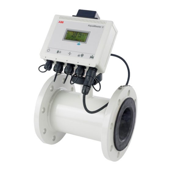
AquaMaster 3
Electromagnetic flowmeter
The smart solution for
remote applications
Introduction
TM
AquaMaster 3
is a range of high performance
electromagnetic flowmeters for the measurement of
electrically-conductive fluids and is normally supplied as
factory-configured, calibrated systems.
This User Guide provides end-user details for
AquaMaster 3 close-coupled and remote transmitters.
When the meter is taken out of storage and installed for
first use, remove the protective label (if fitted) from the
front to enable light to activate the unit.
If the meter is not powered, connect any batteries or
external supply as detailed in this manual.
This User Guide should be used in conjunction with the
following publications:
–
Programming Guide (COI/FET2XX–EN)
–
MODBUS Tables Supplement
(COI/FET2XX/MOD/TBL–EN)
Advertisement
Table of Contents

Related Manuals for ABB AquaMaster 3


Summary of Contents for ABB AquaMaster 3
- Page 1 MODBUS Tables Supplement This User Guide provides end-user details for (COI/FET2XX/MOD/TBL–EN) AquaMaster 3 close-coupled and remote transmitters. When the meter is taken out of storage and installed for first use, remove the protective label (if fitted) from the front to enable light to activate the unit.
- Page 2 We are an established world force in the design and manufacture of instrumentation for industrial process control, flow measurement, gas and liquid analysis and environmental applications. As a part of ABB, a world leader in process automation technology, we offer customers application expertise, service and support worldwide.
-
Page 3: Table Of Contents
Installing a SIM Card ........................15 Electrical Installation ........................16 Grounding ..............................16 Connections ..............................18 3.2.1 AquaMaster 3 Connections ......................18 3.2.2 Use of Tamper-detection Seals ....................19 Input / Output Connections ......................... 20 3.3.1 Frequency Outputs ........................20 3.3.2... - Page 4 AquaMaster 3 Electromagnetic flowmeter Start-Up and Operation ......................... 31 Start-up ............................... 31 Display Activation ............................32 Display Information ............................32 Servicing Plugs and Sockets ........................33 4.4.1 Service Intervals ..........................33 4.4.2 Equipment Required ........................34 4.4.3 Preparation ........................... 34 4.4.4...
-
Page 5: Safety
AquaMaster 3 Electromagnetic flowmeter 1 Safety 1 Safety Information in this manual is intended only to assist our customers in the efficient operation of our equipment. Use of this manual for any other purpose is specifically prohibited and its contents are not to be reproduced in full or part without prior approval of the Technical Publications Department. -
Page 6: Health & Safety
AquaMaster 3 Electromagnetic flowmeter 1 Safety 1.3 Health & Safety Health and Safety To ensure that our products are safe and without risk to health, the following points must be noted: The relevant sections of these instructions must be read carefully before proceeding. -
Page 7: Mechanical Installation
AquaMaster 3 Electromagnetic flowmeter 2 Mechanical Installation 2 Mechanical Installation 2.1 Unpacking Fig. 2.1 Unpacking 2.2 Installation Conditions Caution. Do NOT exceed the maximum working pressure marked on the equipment. Fig. 2.2 Spillage User Guide OI/FET2XX–EN Rev. E... -
Page 8: Electromagnetic Flowmeter
AquaMaster 3 Electromagnetic flowmeter 2 Mechanical Installation Fig. 2.3 Vibration Fig. 2.4 Localized Heat Close-coupled Version Allow room to read data plate Fig. 2.5 Siting User Guide OI/FET2XX–EN Rev. E... -
Page 9: Electromagnetic Flowmeter
AquaMaster 3 Electromagnetic flowmeter 2 Mechanical Installation 60 °C (140 °F) Maximum 70 °C (158 °F) Maximum –20 °C –10 °C (–4 °F) (14 °F) Minimum Minimum Fig. 2.6 Within Temperature Limits Full Bore Sensor (MM/GF) 2 Pipe Diameters 5 Pipe Diameters... -
Page 10: Electromagnetic Flowmeter
AquaMaster 3 Electromagnetic flowmeter 2 Mechanical Installation Fig. 2.9 Shade <2 m 78 in.) Submerged – 9 Months IP68 (NEMA 6P) Accrued Time ENCLOSURE 6P Not applicable to GSM Integral Aerial Installations – see section 2.4.1, page 13 Fig. 2.10 Within Environmental Rating Supports Fig. -
Page 11: Electromagnetic Flowmeter
2 Mechanical Installation Adequate Backfill Protection Plate (Recommended) Fig. 2.13 Underground Note. For further details when burying flow sensors contact the ABB Service Organisation. Fig. 2.14 Cable Routing Fit Gaskets Gaskets same size as pipe Fig. 2.15 Gasket Fitting User Guide OI/FET2XX–EN Rev. E... -
Page 12: Electromagnetic Flowmeter
AquaMaster 3 Electromagnetic flowmeter 2 Mechanical Installation For access to display and communication connector Fig. 2.16 Access to Transmitter 0.7 m (2.3 ft.) Minimum Fig. 2.17 Separation of Sensors Pressure Transducer Pressure Transducer Fig. 2.18 Pressure Transducer – Protect from Frost... -
Page 13: Dimensions
(5.4) (7.3) 280 (11.0) with Connectors 177 (7.0) (4.1) Sensor-mounted Transmitter Fig. 2.19 AquaMaster 3 Dimensions Dimensions in mm (in.) 8 (0.30) 135 (5.30) 135 (5.30) 70 (2.75) Fig. 2.20 AquaMaster 3 Battery Pack Dimensions User Guide OI/FET2XX–EN Rev. E... -
Page 14: Terminal Box - Sensor-Mounted
AquaMaster 3 Electromagnetic flowmeter 2 Mechanical Installation 2.3.2 Terminal Box – Sensor-mounted Dimensions in mm (in.) 80 (3.2) 36.5 (1.43) 62 (2.44) 100 (3.93) Fig. 2.21 Round Terminal Box Dimensions User Guide OI/FET2XX–EN Rev. E... -
Page 15: Gsm-Equipped Transmitters
AquaMaster 3 Electromagnetic flowmeter 2 Mechanical Installation 2.4 GSM-equipped Transmitters 2.4.1 GSM Antenna Installation Before deciding on an antenna mounting location, check that the local signal strength for the chosen mobile phone network is satisfactory. Use the GSM-equipped transmitter's integral signal strength test facility to establish signal strength. -
Page 16: Connecting A Remote Antenna
AquaMaster 3 Electromagnetic flowmeter 2 Mechanical Installation >50 mm (2.0 in.) Fig. 2.23 GSM Antenna Installation 2.4.2 Connecting a Remote Antenna Referring to Fig. 2.24: 1. Remove the cover from the socket on top of the transmitter. 2. Gently push the antenna plug into the socket, then twist the screw ring clockwise until locked. -
Page 17: Installing A Sim Card
AquaMaster 3 Electromagnetic flowmeter 2 Mechanical Installation 2.4.3 Installing a SIM Card Referring to Fig. 2.25: 1. Remove the transmitter from its mounting point. 2. Use water to wash off any loose dirt from the case and dry the area around the SIM cover. -
Page 18: Electrical Installation
AquaMaster 3 Electromagnetic flowmeter 3 Electrical Installation 3 Electrical Installation 3.1 Grounding Caution. For safety reasons and optimum performance, the flowmeter, pipelines and medium must be bonded and grounded correctly according to regulations. Note. Connect the transmitter ground connection to the flowmeter body ground –... -
Page 19: Electromagnetic Flowmeter
AquaMaster 3 Electromagnetic flowmeter 3 Electrical Installation Fig. 3.2 AquaMaster 3 Transmitter Mounted in a Chamber (Battery Version Shown) Fig. 3.3 AquaMaster 3 Transmitter Mounted in a Cabinet (Battery Version Shown) User Guide OI/FET2XX–EN Rev. E... -
Page 20: Connections
Electromagnetic flowmeter 3 Electrical Installation 3.2 Connections Note. Refer to Section Fig. 3.4, page 25 for MODBUS connection. 3.2.1 AquaMaster 3 Connections Referring to Fig. 3.4: 1. Remove the screwed cap on the sensor connector. 2. Gently push the sensor plug into the socket and rotate it until it engages, then tighten the locking ring. -
Page 21: Use Of Tamper-Detection Seals
AquaMaster 3 Electromagnetic flowmeter 3 Electrical Installation 3.2.2 Use of Tamper-detection Seals Referring to Fig. 3.5: 1. Pass the wire of the seal through both the hole in the locking-ring and the matching hole in the front of the transmitter. -
Page 22: Input / Output Connections
Operation of outputs is programmable – see Programming Guide (COI/FET2XX–EN) for details. External isolators are not normally required as the pulse and alarm circuit is electrically-separated from all other AquaMaster 3 connections. Capacitive loads must be inrush current limited. -
Page 23: Alarm Interface
AquaMaster 3 Electromagnetic flowmeter 3 Electrical Installation 3.3.2 Alarm Interface Common Alarm Input O/P 3 Fig. 3.7 Alarm Output Connections Note. Output 3 is not polarity sensitive. The common connection for these outputs is designated ‘COM’. 3.3.3 Input / Output Connections... -
Page 24: Scanreader Interface (Option)
Note. The serial port connection shares the same physical port as the MODBUS connection so (depending on cable design) it may be necessary to disconnect the MODBUS connection temporarily to enable configuration of AquaMaster 3. User Guide OI/FET2XX–EN Rev. E... -
Page 25: Pressure Transducer (Optional)
AquaMaster 3 Electromagnetic flowmeter 3 Electrical Installation 3.3.6 Pressure Transducer (Optional) Optional pressure transducer cables are available for a range of pressures and cable lengths. Fig. 3.11 Optional Pressure Transducer Connector Caution. Use only the pressure transducer supplied with the transmitter. Use of other pressure transducers requires alteration of the pressure span and zero factors in the transmitter. -
Page 26: Anti-Tamper Protection
OIML R49 the flowmeter can be sealed to prevent unauthorized changes to the meter settings and configuration. A read-only switch / link is used (as detailed in Fig. 3.12) to prevent login through any communication means and modification of any parameters on the AquaMaster 3. Not used... -
Page 27: Modbus Connection
AquaMaster 3 Electromagnetic flowmeter 3 Electrical Installation 3.4 MODBUS Connection This section describes the AquaMaster 3 MODBUS serial data communications option and must be used in conjunction with: MODBUS Tables Supplement (COI/FET2XX/MOD/TBL–EN) Programming Guide (COI/FET2XX–EN) Detailed specifications and recommendations for using and implementing MODBUS communications are contained in the following external publications: ... -
Page 28: 2-Wire Connection
AquaMaster 3 Electromagnetic flowmeter 3 Electrical Installation 3.4.1 2-wire Connection AquaMaster 3 MODBUS RS485 uses a 2-wire serial link in accordance with EIA/TIA-485 standard – see Fig. 3.14. Master Line Pull Up Terminator Balanced Pair Line Terminator Pull Down Common... -
Page 29: Termination Resistor
AquaMaster 3 Electromagnetic flowmeter 3 Electrical Installation 3.4.4 Termination Resistor To minimize transmission line travelling wave reflections caused by impedance discontinuities at the end of the described RS485-cable a Line Termination is required near each of the 2 ends of the 'Bus' as described in the MODBUS over Serial Line –... -
Page 30: Power Supply Connections
Power supply connections / earthing arrangements are identical for cathodically-protected remote transmitter systems. For cathodically-protected integral transmitter systems, follow cathodic installation practices. AquaMaster 3 has 3 power supply options: – Mains power – see Section 3.5.1 – Battery power – see Section 3.5.2, page 29 –... -
Page 31: Battery Power Supply
3.5.2 Battery Power Supply Note. Before making connections, check the Data label to confirm power supply requirements. AquaMaster 3 can be powered from Explorer-style battery packs fitted with the MIL plastic style plug. The Explorer battery capacity is of published life. -
Page 32: Renewable Energy Supply
For these reasons, in some installations, generators with a capacity greater then the specified 5 W minimum should be used. Contact ABB for a technical note, giving guidance on the selection of suitable sized generators for AquaMaster 3. -
Page 33: Start-Up And Operation
4 Start-Up and Operation Warning. The battery pack used by AquaMaster 3 may present a risk of fire or chemical burns if mistreated. Do not recharge, disassemble, heat above 100 °C (212 °F) or incinerate. Replace battery pack with an ABB-supplied part only. Use of another battery may present a risk of fire or explosion. -
Page 34: Display Activation
To activate the display during normal operation: 1. Cover the display area for a few seconds. 2. Uncover the display area. The display is activated and the AquaMaster 3 cycles through the programmed set of display measurements. Note. To use local or remote serial communications, for instructions on how to alter the displayed set of measurements and for meter setup, refer to COI/FET2XX–EN. -
Page 35: Servicing Plugs And Sockets
Electromagnetic flowmeter 4 Start-Up and Operation 4.4 Servicing Plugs and Sockets To ensure long and reliable service life for the plugs and sockets on AquaMaster 3 Flow Transmitters, ABB recommend regular treatment of the gold connector pins. Connectors Fig. 4.2 Transmitter Sockets (MIL Style) 4.4.1 Service Intervals... -
Page 36: Equipment Required
AquaMaster 3 Electromagnetic flowmeter 4 Start-Up and Operation 4.4.2 Equipment Required Cleaners are available from your local ABB representative. To purchase supplies directly or for local distributor details please go to the following website: http://store.caig.com/ Material details are: Description Part No. -
Page 37: Order Of Treatment
AquaMaster 3 Electromagnetic flowmeter 4 Start-Up and Operation 4.4.5 Order of Treatment To minimize disruptive effects of repeatedly breaking and making connections perform the following order of treatment using the Stage 1 and Stage 2 processes for each plug and socket in turn: 1. -
Page 38: Stage 2 - Oxide Prevention
AquaMaster 3 Electromagnetic flowmeter 4 Start-Up and Operation 4.4.7 Stage 2 – Oxide Prevention To prevent oxide build-up: 1. Apply a very short burst (not more than 0.5 s duration) of DeoxIT Gold GN5 spray to the metal surfaces. Avoid unnecessary spraying onto transmitter housing. -
Page 39: Accessories / Spares Kits
4 Start-Up and Operation 4.5 Accessories / Spares Kits Common MRBX9969 Close-coupled mounting kit WEBC2100 AquaMaster 3 local communications adapter WEBC2003/01 Remote GSM aerial kit 1 m (3.3 ft.) WEBC2003/05 Remote GSM aerial kit 5 m (16.4 ft.) B20433 4-pin MIL – renewable power connector B20434 7-pin MIL –... -
Page 40: Specification
AquaMaster 3 Electromagnetic flowmeter 5 Specification 5 Specification Specification – flowmeter Battery- or renewable energy powered reduced bore meters – flow specifications OIML Class 2 specification OIML Class 1 specification Size (0.5%) (Ugal / min) (Ugal / min) (Ugal / min) - Page 41 AquaMaster 3 Electromagnetic flowmeter 5 Specification Battery- or renewable energy powered full bore meters – flow specifications Class 2 specification (0.5%) (Ugal / min) (Ugal / min) (Ugal / min) (Ugal / min) (Ugal / min) 20 (88) 16 (70) 1.1 (4.83)
- Page 42 AquaMaster 3 Electromagnetic flowmeter 5 Specification AC-powered reduced bore meters – flow specifications OIML Class 2 specification OIML Class 1 specification Size (0.25%) (Ugal / min) (Ugal / min) (Ugal / min) (Ugal / min) (Ugal / min) (Ugal / min)
- Page 43 AquaMaster 3 Electromagnetic flowmeter 5 Specification AC-powered full bore meters – flow specifications Class 2 specification (0.25%) (Ugal / min) (Ugal / min) (Ugal / min) (Ugal / min) (Ugal / min) 20 (88) 16 (70) 1.6 (7) 0.08 (0.35) 0.05 (0.22)
- Page 44 AquaMaster 3 Electromagnetic flowmeter 5 Specification Specification – sensor Wetted materials End connections Screw-end meters Thread-end connections (MM/GA) Brass and stainless steel 316L 15 mm – ISO 228 G in. B in. NPSM 20 mm – ISO 228 G 1 in. B 1 in. NPSM Flanged meters 25 mm –...
- Page 45 Backup power time up to 3 weeks (dependent on Compatible readers operating conditions) Severn Trent Services Smart reader External battery pack ABB or Elster SR100 and SR50 IP68 (NEMA 6P) Logicon Versaprobe Manganese alkaline battery life: Itron ERT 0 to 45 °C (32 to 113 °F) typically 5 years...
- Page 46 AquaMaster 3 Electromagnetic flowmeter 5 Specification Temperature ranges Telemetry applications (option) GSM / SMS Modem Mounting: Storage Ambient Internal Frequency bands: Quad band: 850 / 900 / 1800 / 1900 MHz 70 °C (158 °F) 60 °C (140 °F) Functions: SMS auto report of flow and optionally pressure logger data (typically 1 s or 1 min.
- Page 47 AquaMaster 3 Electromagnetic flowmeter 5 Specification Mounting 45 ° Maximum Sensor Electrodes Pipe conditions >5 x pipe dia. >2 x pipe dia. MM/GF MM/GA 0 x pipe dia. 0 x pipe dia. minimum minimum Flow Direction Pressure loss (MM/GA only)
- Page 48 2 year @15 min @ 1 min Software compatibility Software Direct RS232 SMS (Text) ABB AC800M ABB Generic (for example, LogMaster) ABB Logger Server (AMI) Areal (Topkapi) AutoChart ...
- Page 49 AquaMaster 3 Electromagnetic flowmeter 5 Specification Sensor Specification (Nominal Dimensions) 15 to 25 mm ( to 1 in.) – Screw Ends (MM/GA) Dimensions Meter Size Approx. Weight mm (in.) Connection 119 (4.7) in. B or in. NPSM 127 (5) G 1 in. B or 1 in. NPSM 127 (5) in.
- Page 50 AquaMaster 3 Electromagnetic flowmeter 5 Specification 40 to 300 mm (1 to 12 in.) – Flanged (MM/GA) Meter Size Dimensions mm (in.) Approx. Weight 150 (5.9) 200 (7.9) 165 (6.5) 200 (7.9) 219 (8.6) 200 (7.9) 200 (7.9) 200 (7.9) 220 (8.6)
- Page 51 AquaMaster 3 Electromagnetic flowmeter 5 Specification 350 to 600 mm (14 to 24 in.) – Flanged (MM/GA) Meter Size Dimensions mm (in.) Approx. Weight 513 (20.2) 520 (20.5) 550 (21.7) 570 (22.4) 576 (22.7) 600 (23.6) 632 (24.9) 627 (24.7) 698 (27.5)
- Page 52 AquaMaster 3 Electromagnetic flowmeter 5 Specification 25 to 300 mm (1 to 12 in.) – Full Bore (MM/GF) Meter Size Dimensions mm (in.) Approx. Weight 115 (4.5) 200 (7.9) 150 (5.9) 200 (7.9) 165 (6.5) 200 (7.9) 185 (7.3) 200 (7.9) 200 (7.9)
-
Page 53: Appendix A Hazardous Area Protection
AquaMaster 3 Electromagnetic flowmeter Appendix A Hazardous Area Protection Appendix A Hazardous Area Protection A.1 GSM-Equipped Units – Safety Precautions The following safety precautions must be observed during all phases of the operation, usage, service or repair of this GSM cellular terminal. Failure to comply with these precautions violates safety standards of design, manufacture and intended use of the product. -
Page 54: Notes
AquaMaster 3 Electromagnetic flowmeter Notes Notes User Guide OI/FET2XX–EN Rev. E... - Page 55 Repair Centre. — Metals and Minerals — Oil, Gas & Petrochemical — Pulp and Paper ABB Limited Tel: +44 (0)1453 826661 Drives and Motors Fax: +44 (0)1453 829671 — AC and 6 Drives, AC and DC Machines, AC Motors to —...
- Page 56 Oldends Lane document without prior notice. With regard to Stonehouse purchase orders, the agreed particulars shall prevail. ABB does not accept any responsibility Gloucestershire GL10 3TA whatsoever for potential errors or possible lack of information in this document. Tel:...