Table of Contents
Advertisement
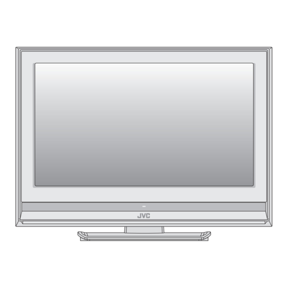
SERVICE MANUAL
LCD INTEGRATED DIGITAL TELEVISION
2007
4 S ERVICE MANUAL
YA509
LT-26A80SU, LT-26A80ZU, LT-26DA8BJ,
LT-26DA8SJ, LT-26DA8SU, LT-26DA8ZU,
LT-26DT8ZJ, LT-32A80SU, LT-32A80ZU,
LT-32DA8BJ, LT-32DA8SJ, LT-32DA8SU,
LT-32DA8ZU, LT-32DT8ZJ
[A80 series]
[DA8 series]
[DT8 series]
COPYRIGHT © 2007 Victor Company of Japan, Limited
1
PRECAUTION. . . . . . . . . . . . . . . . . . . . . . . . . . . . . . . . . . . . . . . . . . . . . . . . . . . . . . . . . . . . . . . . . . . . . . . . . 1-4
2
SPECIFIC SERVICE INSTRUCTIONS . . . . . . . . . . . . . . . . . . . . . . . . . . . . . . . . . . . . . . . . . . . . . . . . . . . . . . 1-8
3
DISASSEMBLY . . . . . . . . . . . . . . . . . . . . . . . . . . . . . . . . . . . . . . . . . . . . . . . . . . . . . . . . . . . . . . . . . . . . . . 1-13
4
ADJUSTMENT . . . . . . . . . . . . . . . . . . . . . . . . . . . . . . . . . . . . . . . . . . . . . . . . . . . . . . . . . . . . . . . . . . . . . . . 1-18
5
TROUBLESHOOTING . . . . . . . . . . . . . . . . . . . . . . . . . . . . . . . . . . . . . . . . . . . . . . . . . . . . . . . . . . . . . . . . . 1-22
TABLE OF CONTENTS
COPYRIGHT © 2007 Victor Company of Japan, Limited
BASIC CHASSIS
FT3
No.YA509
2007/4
Advertisement
Chapters
Table of Contents

Related Manuals for JVC LT-26A80SU


Summary of Contents for JVC LT-26A80SU
-
Page 1: Table Of Contents
SERVICE MANUAL LCD INTEGRATED DIGITAL TELEVISION YA509 2007 4 S ERVICE MANUAL LT-26A80SU, LT-26A80ZU, LT-26DA8BJ, LT-26DA8SJ, LT-26DA8SU, LT-26DA8ZU, LT-26DT8ZJ, LT-32A80SU, LT-32A80ZU, LT-32DA8BJ, LT-32DA8SJ, LT-32DA8SU, LT-32DA8ZU, LT-32DT8ZJ BASIC CHASSIS [A80 series] [DA8 series] [DT8 series] COPYRIGHT © 2007 Victor Company of Japan, Limited TABLE OF CONTENTS PRECAUTION. - Page 2 SPECIFICATION Contents LT-26DA8BJ Items LT-26A80SU LT-26DA8SU LT-26DA8SJ LT-26A80ZU LT-26DA8ZU LT-26DT8ZJ Dimensions ( W × H × D ) 67.2 cm × 51.9 cm × 23.0 cm [Included stand] 67.2 cm × 47.1 cm × 10.7 cm [TV only] Mass 11.2 kg [Included stand] 11.6 kg [Included stand]...
- Page 3 Contents LT-32DA8BJ Items LT-32A80SU LT-32DA8SU LT-32DA8SJ LT-32A80ZU LT-32DA8ZU LT-32DT8ZJ Dimensions ( W × H × D ) 80.0 cm × 59.1 cm × 23.0 cm [Included stand] 80.0 cm × 54.5 cm × 9.9 cm [TV only] Mass 13.8 kg [Included stand] 14.3 kg [Included stand] 13.0 kg [TV only] 13.5 kg [TV only]...
-
Page 4: Precaution
SECTION 1 PRECAUTION SAFETY PRECAUTIONS [EXCEPT FOR UK] (1) The design of this product contains special hardware, (6) Isolation Check (Safety for Electrical Shock Hazard) many circuits and components specially for safety After re-assembling the product, always perform an purposes. For continued protection, no changes should be isolation check on the exposed metal parts of the cabinet made to the original design unless authorized in writing by (antenna terminals, video/audio input and output terminals,... - Page 5 SAFETY PRECAUTIONS [FOR UK] (1) The design of this product contains special hardware and many circuits and components specially for safety purposes. For continued protection, no changes should be made to the original design unless authorized in writing by the manufacturer. Replacement parts must be identical to those used in the original circuits.
- Page 6 INSTALLATION 1.3.1 HEAT DISSIPATION 1.3.3 INSTALLATION REQUIREMENTS If the heat dissipation vent behind this unit is blocked, cooling To ensure safety in an emergency such as an earthquake, and efficiency may deteriorate and temperature inside the unit will to prevent accidents, ensure that measures are taken to prevent rise.
- Page 7 HANDLING LCD PANEL 1.4.1 PRECAUTIONS FOR TRANSPORTATION 1.4.2 OPTICAL FILTER (ON THE FRONT OF THE LCD PANEL) When transporting the unit, pressure exerted on the internal LCD (1) Avoid placing the unit under direct sunlight over a panel due to improper handling (such as tossing and dropping) prolonged period of time.
-
Page 8: Specific Service Instructions
2.SELF_CHECK 3.I2C STOP 3.I2C STOP Fig. 2-1 Press [9] key SHIPPING SCREEN PR List Empty *** SHIPPING STRAT *** *** SHIPPING STRAT *** Fig. 2-2 MAIN DIFFERENCE LIST LT-26A80SU LT-26A80ZU LT-26DA8SU LT-26DA8ZU LT-26DA8BJ LT-26DA8SJ LT-26DT8ZJ Item LT-32A80SU LT-32A80ZU LT-32DA8SU LT-32DA8ZU... - Page 9 21-PIN EURO CONNECTOR (SCART) : EXT-1 / EXT-2 Pin No. Signal designation Matching value EXT-1 EXT-2 AUDIO R output 500mV(rms) (Nominal), Low impedance Used (TV OUT) Used (LINE OUT) AUDIO R input 500mV(rms) (Nominal), High impedance Used (R1) Used (R2) AUDIO L output 500mV(rms) (Nominal), Low impedance Used (TV OUT)
- Page 10 TECHNICAL INFORMATION 2.5.1 LCD PANEL This unit uses the flat type panel LCD (Liquid Crystal Display) panel that occupies as little space as possible, instead of the conventional CRT (Cathode Ray Tube), as a display unit. Since the unit has the two polarizing filter that are at right angles to each other, the unit adopts "normally black" mode, where light does not pass through the polarizing filter and the screen is black when no voltage is applied to the liquid crystals.
- Page 11 2.5.2 MAIN CPU PIN FUNCTION [IC7001 : MAIN PWB] Pin name Function Pin name Function VSUP3.3COM 3.3V power supply T-V LINK_OUT Data output for T-V LINK X'TALIN 20.25MHz oscillation for CPU system clock POWER_G Not used : Low power voltage detection [NG = H] X'TALOUT 20.25MHz oscillation for CPU system clock PROTECTOR...
- Page 12 Pin name Function DRO1_5 Not used DRO1_6 Not used VSUP3.3LVDS 3.3V power supply DRO1_8 Not used DRO1_9 Not used RF AGC voltage for VHF/UHF tuner KEY1 Key scan for side control (POWER/CH+/CH-/MENU) SLOW1 EXT-1 SLOW detection SLOW2 EXT-2 SLOW detection GND3.3DAC VSUP3.3DAC 3.3V power supply...
-
Page 13: Disassembly
SECTION 3 DISASSEMBLY DISASSEMBLY PROCEDURE • Be sure to perform the SYSTEM SETTEING, at the end of the procedure. • Make sure that the power cord is disconnected from the outlet. • Pay special attention not to break or damage the parts. •... - Page 14 DIGITAL STAND BASE COVER BASE REAR COVER MAIN PWB SHIELD COVER DIGITAL POWER PWB TUNER UNIT [DA8/DT8 series] STAND ASS'Y MAIN BASE POWER CORD STAND BASE CONTROL PWB COVER POWER CORD HOLDER INVERTER PWB COVER SPEAKER CONTROL INVERTER PWB FRONT PANEL LED PWB SPEAKER SPACER...
- Page 15 MEMORY IC REPLACEMENT • This model uses the memory IC. • This memory IC stores data for proper operation of the video and drive circuits. • When replacing, be sure to use an IC containing this (initial value) data. 3.2.1 MEMORY IC TABLE Simbol Number of pins Mounting PWB Main content of data...
- Page 16 3.2.4 SETTINGS OF FACTORY SHIPMENT 3.2.4.1 BUTTON OPERATION 3.2.4.2 REMOTE CONTROL DIRECT OPERATION Setting item Setting position Setting item Setting position POWER CHANNEL CHANNEL VOLUME VOLUME ZOOM AUTO TV/AV SUB POWER 3.2.4.3 REMOTE CONTROL MENU OPERATION (1) PICTURE (6) DTV [DA8/DT8 series only] [For UK] Setting item Setting position...
- Page 17 REPLACEMENT OF CHIP COMPONENT 3.3.1 CAUTIONS (1) Avoid heating for more than 3 seconds. (2) Do not rub the electrodes and the resist parts of the pattern. (3) When removing a chip part, melt the solder adequately. (4) Do not reuse a chip part after removing it. 3.3.2 SOLDERING IRON (1) Use a high insulation soldering iron with a thin pointed end of it.
-
Page 18: Adjustment
SECTION 4 ADJUSTMENT ADJUSTMENT PREPARATION (1) This TV is adjusted by using REMOTE CONTROL UNIT. (2) The adjustment using the REMOTE CONTROL UNIT is made on the basis of the initial setting values. The setting values which adjust the screen to the optimum condition can be different from the initial setting values. (3) Make sure that connection is correctly made AC to AC power source. - Page 19 4.5.5 ADJUSTMENT MODE This mode is used to adjust the VIDEO CIRCUIT. 4.5.5.1 HOW TO ENTER THE ADJUSTMENT MODE When the SERVICE MENU SCREEN of SERVICE MODE is displayed, press [1] key to enter the ADJUSTMENT MODE (Fig.2). NOTE: • When a number key other than the [1] key is pressed in the SERVICE MODE SCREEN, the other relevant screen may be displayed.
- Page 20 INITIAL SETTING VALUES IN THE SERVICE MODE • Perform fine-tuning based on the "initial values" using the remote control when in the Service mode. • The "initial values" serve only as an indication rough standard and therefore the values with which optimal display can be achieved may be different from the default values.
- Page 21 ADJUSTMENT PROCEDURE 4.7.1 VIDEO CIRCUIT Measuring Item Test point Adjustment part Description instrument COLOUR Remote [1.ADJUST] (1) Receive a PAL colour bar signal. DECODER control unit 1.SC ADJ (2) Select "1.ADJUST" from the SERVICE MODE. (3) Select <1.SC ADJ>. Signal (4) Adjust the value of <1.SC ADJ>...
-
Page 22: Troubleshooting
SECTION 5 TROUBLESHOOTING SELF CHECK FEATURE SERVICE MENU SCREEN 5.1.1 OUTLINE This unit comes with the "Self check" feature, which checks the operational state of the circuit and displays/saves it during SERVICE MENU SERVICE MENU failure.Diagnosis is performed when power is turned on, and 1.ADJUST 1.ADJUST information input to the main microcomputer is monitored at all... - Page 23 5.1.6 DETAILS Self check is performed for the following items: <Page 1 of screen> Diagnosis Detection item Display Detection content Detection timing signal (line) Low bias line short Confirm the operation of the low bais(5V/12V/ LB_PRO Detection starts 5 seconds after protection 13.5V/14V) protection circuit.
- Page 24 Victor company of Japan, Limited Display category 12, 3-chome, Moriya-cho, Kanagawa-ku, Yokohama-city, Kanagawa-prefecture, 221-8528, Japan (No.YA509) Printed in Japan...
- Page 25 SCHEMATIC DIAGRAMS LCD INTEGRATED DIGITAL TELEVISION LT-26A80SU, LT-26A80ZU, LT-26DA8BJ, LT-26DA8SJ, LT-26DA8SU, LT-26DA8ZU, LT-26DT8ZJ, LT-32A80SU, LT-32A80ZU, LT-32DA8BJ, LT-32DA8SJ, LT-32DA8SU, LT-32DA8ZU, LT-32DT8ZJ CD-ROM No.SML200704 BASIC CHASSIS [A80 series] [DA8 series] [DT8 series] No.YA509 COPYRIGHT © 2007 Victor Company of Japan, Limited. 2007/4...
- Page 26 LT-26A80SU LT-26A80ZU LT-26DA8BJ, LT-26DA8SJ LT-26DA8SU LT-26DA8ZU LT-26DT8ZJ LT-32A80SU LT-32A80ZU LT-32DA8BJ LT-32DA8SJ LT-32DA8SU, LT-32DA8ZU LT-32DT8ZJ STANDARD CIRCUIT DIAGRAM NOTE ON USING CIRCUIT DIAGRAMS 1.SAFETY Type No indication : Ceramic capacitor The components identified by the symbol and shading are : Metalized mylar capacitor critical for safety.
- Page 27 MAIN PWB PATTERN ..........................2-19 POWER PWB PATTERN .......................... 2-23 LED PWB PATTERN ..........................2-24 SW PWB PATTERN ..........................2-24 VOLTAGE CHARTS .................. 2-25 WAVEFORMS .................... 2-26 USING P.W. BOARD P.W.B ASS’Y name LT-26A80SU LT-26A80ZU LT-26DA8BJ LT-26DA8SJ LT-26DT8ZJ LT-26DA8SU LT-26DA8ZU MAIN P.W. BOARD...
-
Page 28: Wiring Diagram
WIRING DIAGRAM LCD PANEL UNIT [CONTROL PWB] LCD PANEL UNIT [INVERTER PWB] [DA8/DT8 SERIES ONLY] CN900W CN900A CN101A CN00LV CN900P CN100F CN900F PL207 PL200 PL107 CN10UD PL103 CN10UU DIGITAL TUNER CN10LR CN10UA CN100R CN10UV DIGITAL TUNER UNIT SW PWB CN100U F9001 250V/6.3A ANALOG TUNER... -
Page 29: Block Diagram
BLOCK DIAGRAM [only LT-26DA8BJ/SU/ZU, LT-32DA8BJ/SU/ZU] D_BY D_RY DIGITAL D_CV TUNER UNIT MAIN PWB IC7001 TU1001 MICROCOMPUTER/TELETEXT DECODE/ TV_CV IF PROCESS/VIDEO PROCESS/AUDIO PROCESS/ VHF/UHF TUNER D_BY TV_CV D_CV D_RY AV SELECT/RGB PROCESS/A-D CONVERT/LVDS SPEAKER L SORROUND/ IC6001 SOUND DV1_R0-7 EXT-4 HDMI 1 TONE/ D-A CONVERT DEMODULATE... -
Page 30: Circuit Diagrams
MAIN PWB CIRCUIT DIAGRAM (1/3) SHEET 1 UNIT [DA8/DT8 SERIES ONLY] SFT-1003A-U2 DIGITAL TUNER LED PWB ASS'Y DIGITAL TUNER UNIT SHEET 2 DIGITAL CN80U1 [LT-26A80SU,LT-26A80ZU] UNIT [DA8/DT8 SERIES ONLY] INPUT (SHEET 5) DIGITAL [DA8/DT8 OPEN OPEN BLOCK SFT-1001A-U2 SHEET 2... - Page 31 MAIN PWB CIRCUIT DIAGRAM (2/3) SHEET 2 MAIN PWB ASS'Y(2/3) DIGITAL SFT-1003A-U2 INPUT BLOCK SHEET 1,3 [LT-26A80SU,LT-26A80ZU] SFT-1001A-U2 SHEET 1 SHEET 1 SHEET 1 SHEET 1 [LT-26DA8BJ,LT-26DA8SJ, LT-26DT8ZJ] SFT-1008A-U2 [LT-26DA8SU,LT-26DA8ZU] STB3.3V R7212 R7213 OPEN SFT-1004A-U2 OPEN Q7021 OPEN [LT-32A80SU,LT-32A80ZU] R7211...
- Page 32 MAIN PWB (DC-DC) CIRCUIT DIAGRAM (3/3) SHEET 3 MAIN PWB ASS'Y(3/3) [DC-DC] SFT-1003A-U2 [LT-26A80SU,LT-26A80ZU] SFT-1001A-U2 [LT-26DA8BJ,LT-26DA8SJ,LT-26DT8ZJ] SHEET 1,2 SFT-1008A-U2 [LT-26DA8SU,LT-26DA8ZU] SHEET 1 SHEET 1 SFT-1004A-U2 [LT-32A80SU,LT-32A80ZU] SFT-1002A-U2 [LT-32DA8SJ,LT-32DT8ZJ,LT-32DA8BJ] SFT-1010A-U2 [LT-32DA8SU,LT-32DA8ZU] CN100A R7153 OPEN R7152 OPEN STB3.3V R7151 R7154 OPEN C3001...
-
Page 33: Power Pwb Circuit Diagram
POWER PWB CIRCUIT DIAGRAM SHEET 4 LCD PANEL UNIT LCD PANEL UNIT [INVERTER PWB] [INVERTER PWB] OPEN CN900P CN900Q CN900W GND5 L9501 OPEN Y9008 Y9001 OPEN CN00W2 Y9009 Y9002 C9002 R9006 F9001 OPEN C9513 OPEN C9001 Y9504 CN90PW L9001 LF9001 LF9002 LF9003 R9001... -
Page 34: Led Pwb Circuit Diagram
LED PWB CIRCUIT DIAGRAM SHEET 5 CN800U OPEN R8903 R8902 OPEN C8901 R8904 R8901 10/10 CN80U1 Q8903 Q8902 STB5V MAIN PWB ASS'Y(1/3) Q8904 CN100U Q8901 (SHEET 1) D8903 OPEN D8902 D8906 OPEN OPEN D8905 D8901 OPEN POWER D8904 OPEN R8905 OPEN IC8951 OPEN... - Page 35 SW PWB CIRCUIT DIAGRAM SHEET 6 POWER/CONTROL SWITCH S7101 S7101 S7102 S7102 S7103 S7103 S7104 S7104 D7101 R7101 CN700R R7102 4.7K 2.2K HEADPHONE R7103 C7004 J7001 OPEN L7001 R7003 MAIN PWB ASS'Y(2/3) CN100R (SHEET 2) C7001 R7001 K7001 C7003 OPEN C7002 R7002 R7004...
-
Page 36: Pattern Diagrams
PATTERN DIAGRAMS MAIN PWB PATTERN [SOLDER SIDE] IP10UA-1 IP10UA-2 IP10UA-3 IP10UD-7 IP10UD-5 IP10UD-3 IP10UD-1 IP10UV-1 IP10UV-2 IP10UV-3 IP10UV-4 IP10UV-5 IP10UV-6 IP10UV-7 IP10UV-8 IP10UV-9 IP10UU-1 IP10UU-2 IP10UU-3 IP10UU-4 IP10UU-5 IP10UD-10 IP10UD-8 IP10UD-6 IP10UD-2 C3044 IP10UD-4 C1216 TP8503 C3044 TP8503 R1221 C3057 C1215 C3081 TP8504... - Page 37 MAIN PWB PATTERN [PARTS SIDE] #PC00047 #PC00048 #PC00046 C9601 C1009 C8903 C1220 CN10UU CN10UA CN10UV CN10UU C8903 CN10UV C1009 C9601 CN10UA C1220 C3035 IC8502 R9451 C3035 C8904 #PC00012 C8901 #PC00016 #PC00023 TU1001 #PC00031 C3031 CN10UD C3127 #PC00028 #PC00013 #PC00032 R8578 R8524 C9452 Q1351...
-
Page 38: Power Pwb Pattern
POWER PWB PATTERN LED PWB PATTERN C9528 L9501 R9534 W9410 Y9504 Y9503 Q9505 R9532 C9520 C9519 C9521 R9527 L9503 D9520 W9404 D9518 W9411 W9405 L9502 W9408 L9504 H9503 H9502 C9529 C9523 C9518 C9517 R8901 D8901 CN80U1 Q8903 CN800U D9514 D8905 D9509 C9514 K9505... -
Page 39: Voltage Charts
VOLTAGE CHARTS WAVEFORMS <MAIN PWB(1/3)> <MAIN PWB(2/3)> MODE MODE MODE MODE MODE MODE MODE MODE MAIN PWB(1/3) DC (V) DC (V) DC (V) DC (V) DC (V) DC (V) DC (V) DC (V) PIN NO. PIN NO. PIN NO. PIN NO. PIN NO. - Page 40 Victor Company of Japan, Limited Display Category 12, 3-chome, Moriya-cho, kanagawa-ku, Yokohama-city, kanagawa-prefecture, 221-8528, Japan (No.YA509) Printed in Japan...
-
Page 41: Parts List
PARTS LIST CAUTION The parts identified by the symbol are important for the safety . Whenever replacing these parts, be sure to use specified ones to secure the safety. The parts not indicated in this Parts List and those which are filled with lines --- in the Parts No. columns will not be supplied. P.W. - Page 42 USING P.W. BOARD & REMOTE CONTROL UNIT ....................3-3 EXPLODED VIEW PARTS LIST ..........................3-4 EXPLODED VIEW ............................... 3-5 PRINTED WIRING BOARD PARTS LIST [LT-26A80SU, LT-26A80ZU] ..............3-6 MAIN P.W. BOARD ASS'Y (SFT-1003A-U2) ..................... 3-6 SW P.W. BOARD ASS'Y (SFT-7201A-U2) ......................3-9 LED P.W.
-
Page 43: Using P.w. Board & Remote Control Unit
USING P.W. BOARD & REMOTE CONTROL UNIT P.W.B ASS'Y No. LT-26DA8BJ P.W.B ASS'Y name LT-26A80SU LT-26DA8SU LT-26DA8SJ LT-26A80ZU LT-26DA8ZU LT-26DT8ZJ MAIN P.W.B SFT-1003A-U2 SFT-1001A-U2 SFT-1008A-U2 ← ← SW P.W.B SFT-7201A-U2 ← ← LED P.W.B SFT-8901A-U2 ← ← POWER P.W.B SFT-9002A-U2 ←... -
Page 44: Exploded View Parts List
TAP SCREW M4 x 16mm(x6) QYSBSF3010MA TAP SCREW M3 x 10mm(x5) QYSPSPD5014MA SCREW M5 x 14mm(x4) LC33651-001A-JK BACK BRACKET (x2) WJZ0247-002A-E WIRE POWER-LCD PANEL LT-26A80ZU,LT-26A80SU,LT-26DA8BJ,LT-26DA8SJ,LT-26DT8ZJ,LT-26DA8SU,LT-26DA8ZU WJZ0248-002A-E WIRE POWER-LCD PANEL LT-32A80SU,LT-32A80ZU,LT-32DA8SJ,LT-32DT8ZJ,LT-32DA8BJ,LT-32DA8SU,LT-32DA8ZU QJK002-091004-E WIRE POWER-MAIN QJK002-080903-E WIRE POWER-MAIN QQR0490-001 NOISE FILTER WJW0041-001A-E... -
Page 45: Exploded View
EXPLODED VIEW [FRONT SIDE] RATING LABEL STAND BASE COVER SHIELD COVER DIGITAL TUNER UNIT [DA8/DT8 series] MAIN BASE STAND BASE CONTROL PWB COVER INVERTER PWB COVER (No.YA509)3-5... -
Page 46: Printed Wiring Board Parts List [Lt-26A80Su, Lt-26A80Zu]
PRINTED WIRING BOARD PARTS LIST [LT-26A80SU, LT-26A80ZU] MAIN P.W. BOARD ASS'Y (SFT-1003A-U2) Ref No. Part No. Part Name Description Local Ref No. Part No. Part Name Description Local D7024 UDZS3.3B-X Z DIODE D7025 UDZS3.3B-X Z DIODE IC1001 MM1510XN-X D7026 UDZW5.6B-X... - Page 47 Ref No. Part No. Part Name Description Local Ref No. Part No. Part Name Description Local C6123 NCB21EK-334X C CAPACITOR 0.33uF 25V K C7078 NCB31CK-104X C CAPACITOR 0.1uF 16V K C6124 NCB31CK-224X C CAPACITOR 0.22uF 16V K C7079 NCB31CK-104X C CAPACITOR 0.1uF 16V K C6125 NCB31CK-224X...
- Page 48 Ref No. Part No. Part Name Description Local Ref No. Part No. Part Name Description Local R1201 NRSA63J-750X MG RESISTOR 75Ω 1/16W J R7016 NRSA63J-221X MG RESISTOR 220Ω 1/16W J R1202 NRSA63J-750X MG RESISTOR 75Ω 1/16W J R7017 NRSA63J-104X MG RESISTOR 100kΩ...
-
Page 49: Sw P.w. Board Ass'y (Sft-7201A-U2)
SW P.W. BOARD ASS'Y (SFT-7201A-U2) Ref No. Part No. Part Name Description Local Ref No. Part No. Part Name Description Local R9321 NRSA63J-472X MG RESISTOR 4.7kΩ 1/16W J R9322 NRSA63J-104X MG RESISTOR 100kΩ 1/16W J D7001 UDZW6.2B-X Z DIODE R9401 NRSA02J-680X MG RESISTOR 68Ω... - Page 50 Ref No. Part No. Part Name Description Local Ref No. Part No. Part Name Description Local D9514 FR105GT-T3 SI DIODE D9515 TL431/A/-T QQR1764-001 CHOKE COIL L9001 D9516 MTZJ16B-T2 Z DIODE L9201 QQL26AM-5R6Z CHOKE COIL 5.6uH M D9517 MTZJ16B-T2 Z DIODE L9502 QQL26AM-5R6Z CHOKE COIL...
-
Page 51: Printed Wiring Board Parts List [Lt-26Da8Bj, Lt-26Da8Sj, Lt-26Dt8Zj]
PRINTED WIRING BOARD PARTS LIST [LT-26DA8BJ, LT-26DA8SJ, LT-26DT8ZJ] MAIN P.W. BOARD ASS'Y (SFT-1001A-U2) Ref No. Part No. Part Name Description Local Ref No. Part No. Part Name Description Local D7011 UDZW3.6B-X Z DIODE D7012 UDZW3.6B-X Z DIODE IC1001 MM1510XN-X D7013 UDZW3.6B-X Z DIODE IC1002... - Page 52 Ref No. Part No. Part Name Description Local Ref No. Part No. Part Name Description Local C6012 NCJ21CK-475X-R C CAPACITOR 4.7uF 16V K C7057 NCB10JK-106X C CAPACITOR 10uF 6.3V K C6104 NCB31CK-105X C CAPACITOR 1uF 16V K C7059 NCB10JK-106X C CAPACITOR 10uF 6.3V K C6105 NCJ21CK-475X-R...
- Page 53 Ref No. Part No. Part Name Description Local Ref No. Part No. Part Name Description Local R1014 NRSA63J-181X MG RESISTOR 180Ω 1/16W J R1359 NRSA63J-103X MG RESISTOR 10kΩ 1/16W J R1015 NRSA63J-222X MG RESISTOR 2.2kΩ 1/16W J R1360 NRSA63J-103X MG RESISTOR 10kΩ...
-
Page 54: Sw P.w. Board Ass'y (Sft-7201A-U2)
Ref No. Part No. Part Name Description Local Ref No. Part No. Part Name Description Local R7087 NRSA63J-122X MG RESISTOR 1.2kΩ 1/16W J L7009 NQL79GM-2R2X COIL 2.2uH M R7088 NRSA63J-104X MG RESISTOR 100kΩ 1/16W J L7010 NRSA02J-0R0X MG RESISTOR 0Ω 1/10W J R7091 NRSA63J-101X MG RESISTOR... -
Page 55: Printed Wiring Board Parts List [Lt-26Da8Su, Lt-26Da8Zu]
PRINTED WIRING BOARD PARTS LIST [LT-26DA8SU, LT-26DA8ZU] MAIN P.W. BOARD ASS'Y (SFT-1008A-U2) Ref No. Part No. Part Name Description Local Ref No. Part No. Part Name Description Local D7011 UDZW3.6B-X Z DIODE D7012 UDZW3.6B-X Z DIODE IC1001 MM1510XN-X D7013 UDZW3.6B-X Z DIODE IC1002 MM1510XN-X... - Page 56 Ref No. Part No. Part Name Description Local Ref No. Part No. Part Name Description Local C6012 NCJ21CK-475X-R C CAPACITOR 4.7uF 16V K C7057 NCB10JK-106X C CAPACITOR 10uF 6.3V K C6104 NCB31CK-105X C CAPACITOR 1uF 16V K C7059 NCB10JK-106X C CAPACITOR 10uF 6.3V K C6105 NCJ21CK-475X-R...
- Page 57 Ref No. Part No. Part Name Description Local Ref No. Part No. Part Name Description Local R1014 NRSA63J-181X MG RESISTOR 180Ω 1/16W J R1359 NRSA63J-103X MG RESISTOR 10kΩ 1/16W J R1015 NRSA63J-222X MG RESISTOR 2.2kΩ 1/16W J R1360 NRSA63J-103X MG RESISTOR 10kΩ...
-
Page 58: Sw P.w. Board Ass'y (Sft-7201A-U2)
Ref No. Part No. Part Name Description Local Ref No. Part No. Part Name Description Local R7087 NRSA63J-122X MG RESISTOR 1.2kΩ 1/16W J L7009 NQL79GM-2R2X COIL 2.2uH M R7088 NRSA63J-104X MG RESISTOR 100kΩ 1/16W J L7010 NRSA02J-0R0X MG RESISTOR 0Ω 1/10W J R7091 NRSA63J-101X MG RESISTOR... -
Page 59: Printed Wiring Board Parts List [Lt-32A80Su, Lt-32A80Zu]
PRINTED WIRING BOARD PARTS LIST [LT-32A80SU, LT-32A80ZU] MAIN P.W. BOARD ASS'Y (SFT-1004A-U2) Ref No. Part No. Part Name Description Local Ref No. Part No. Part Name Description Local D7024 UDZS3.3B-X Z DIODE D7025 UDZS3.3B-X Z DIODE IC1001 MM1510XN-X D7026 UDZW5.6B-X Z DIODE IC1002 MM1510XN-X... - Page 60 Ref No. Part No. Part Name Description Local Ref No. Part No. Part Name Description Local C6123 NCB21EK-334X C CAPACITOR 0.33uF 25V K C7078 NCB31CK-104X C CAPACITOR 0.1uF 16V K C6124 NCB31CK-224X C CAPACITOR 0.22uF 16V K C7079 NCB31CK-104X C CAPACITOR 0.1uF 16V K C6125 NCB31CK-224X...
- Page 61 Ref No. Part No. Part Name Description Local Ref No. Part No. Part Name Description Local R1201 NRSA63J-750X MG RESISTOR 75Ω 1/16W J R7016 NRSA63J-221X MG RESISTOR 220Ω 1/16W J R1202 NRSA63J-750X MG RESISTOR 75Ω 1/16W J R7017 NRSA63J-104X MG RESISTOR 100kΩ...
-
Page 62: Sw P.w. Board Ass'y (Sft-7201A-U2)
SW P.W. BOARD ASS'Y (SFT-7201A-U2) Ref No. Part No. Part Name Description Local REFER TO PARTS LIST IN PAGE 3-9 FOR THIS P.W. BOARD. R9321 NRSA63J-472X MG RESISTOR 4.7kΩ 1/16W J R9322 NRSA63J-104X MG RESISTOR 100kΩ 1/16W J R9401 NRSA02J-680X MG RESISTOR 68Ω... -
Page 63: Printed Wiring Board Parts List [Lt-32Da8Sj, Lt-32Dt8Zj, Lt-32Da8Bj]
PRINTED WIRING BOARD PARTS LIST [LT-32DA8SJ, LT-32DT8ZJ, LT-32DA8BJ] MAIN P.W. BOARD ASS'Y (SFT-1002A-U2) Ref No. Part No. Part Name Description Local Ref No. Part No. Part Name Description Local D7011 UDZW3.6B-X Z DIODE D7012 UDZW3.6B-X Z DIODE IC1001 MM1510XN-X D7013 UDZW3.6B-X Z DIODE IC1002... - Page 64 Ref No. Part No. Part Name Description Local Ref No. Part No. Part Name Description Local C6012 NCJ21CK-475X-R C CAPACITOR 4.7uF 16V K C7057 NCB10JK-106X C CAPACITOR 10uF 6.3V K C6104 NCB31CK-105X C CAPACITOR 1uF 16V K C7059 NCB10JK-106X C CAPACITOR 10uF 6.3V K C6105 NCJ21CK-475X-R...
- Page 65 Ref No. Part No. Part Name Description Local Ref No. Part No. Part Name Description Local R1014 NRSA63J-181X MG RESISTOR 180Ω 1/16W J R1359 NRSA63J-103X MG RESISTOR 10kΩ 1/16W J R1015 NRSA63J-222X MG RESISTOR 2.2kΩ 1/16W J R1360 NRSA63J-103X MG RESISTOR 10kΩ...
-
Page 66: Sw P.w. Board Ass'y (Sft-7201A-U2)
Ref No. Part No. Part Name Description Local Ref No. Part No. Part Name Description Local R7087 NRSA63J-122X MG RESISTOR 1.2kΩ 1/16W J L7009 NQL79GM-2R2X COIL 2.2uH M R7088 NRSA63J-104X MG RESISTOR 100kΩ 1/16W J L7010 NRSA02J-0R0X MG RESISTOR 0Ω 1/10W J R7091 NRSA63J-101X MG RESISTOR... -
Page 67: Printed Wiring Board Parts List [Lt-32Da8Su, Lt-32Da8Zu]
PRINTED WIRING BOARD PARTS LIST [LT-32DA8SU, LT-32DA8ZU] MAIN P.W. BOARD ASS'Y (SFT-1010A-U2) Ref No. Part No. Part Name Description Local Ref No. Part No. Part Name Description Local D7011 UDZW3.6B-X Z DIODE D7012 UDZW3.6B-X Z DIODE IC1001 MM1510XN-X D7013 UDZW3.6B-X Z DIODE IC1002 MM1510XN-X... - Page 68 Ref No. Part No. Part Name Description Local Ref No. Part No. Part Name Description Local C6012 NCJ21CK-475X-R C CAPACITOR 4.7uF 16V K C7057 NCB10JK-106X C CAPACITOR 10uF 6.3V K C6104 NCB31CK-105X C CAPACITOR 1uF 16V K C7059 NCB10JK-106X C CAPACITOR 10uF 6.3V K C6105 NCJ21CK-475X-R...
- Page 69 Ref No. Part No. Part Name Description Local Ref No. Part No. Part Name Description Local R1014 NRSA63J-181X MG RESISTOR 180Ω 1/16W J R1359 NRSA63J-103X MG RESISTOR 10kΩ 1/16W J R1015 NRSA63J-222X MG RESISTOR 2.2kΩ 1/16W J R1360 NRSA63J-103X MG RESISTOR 10kΩ...
-
Page 70: Sw P.w. Board Ass'y (Sft-7201A-U2)
Ref No. Part No. Part Name Description Local Ref No. Part No. Part Name Description Local R7087 NRSA63J-122X MG RESISTOR 1.2kΩ 1/16W J L7009 NQL79GM-2R2X COIL 2.2uH M R7088 NRSA63J-104X MG RESISTOR 100kΩ 1/16W J L7010 NRSA02J-0R0X MG RESISTOR 0Ω 1/10W J R7091 NRSA63J-101X MG RESISTOR... -
Page 71: Remote Control Unit Parts List (Rm-C1508-1C)
REMOTE CONTROL UNIT PARTS LIST (RM-C1508-1C) Ref.No. Part No. Part Name Description Local 000-105200020 BATTERY COVER LT-26A80ZU,LT-26A80SU,LT-32A80SU,LT-32A80ZU REMOTE CONTROL UNIT PARTS LIST (RM-C1821-1C) Ref.No. Part No. Part Name Description Local 2AA070311 BATTERY COVER LT-26DA8BJ,LT-26DA8SJ,LT-26DT8ZJ,LT-26DA8SU,LT-26DA8ZU,LT-32DA8SJ,LT-32DT8ZJ,LT-32DA8BJ,LT-32DA8SU,LT-32DA8ZU (No.YA509)3-31... -
Page 72: Packing
GA10272-087A-U EURO LABEL LT-32DA8SU GA10272-089A-U EURO LABEL LT-32DA8ZU ------------ WARRANTY CARD BT-54031-1 GA30007-001A-U DOCUMENT BAGS ------------ BATTERY AA/R6(x2) LCT2208-001A-U INST BOOK Spanish/English/Italian/German/Portuguese/Dutch/French LT-26A80ZU,LT-26A80SU,LT-32A80SU,LT-32A80ZU LCT2206-001A-U INST BOOK English LT-26DA8BJ,LT-26DA8SJ,LT-26DT8ZJ,LT-32DA8SJ,LT-32DT8ZJ,LT-32DA8BJ LCT2207-001A-U INST BOOK English/German/French/Spanish/Finn/Swedish LT-26DA8SU,LT-26DA8ZU,LT-32DA8SU,LT-32DA8ZU LCT2209-001A-U INST BOOK Danish/Finn/Norwegian/Swedish LT-26A80ZU,LT-26A80SU,LT-32A80SU,LT-32A80ZU ...