Advertisement
Quick Links
MCT
MCT-501
MCT
MCT
-501
-501
-501
Advanced Acoustic Sensor / PowerCode Transmitter
1 1 1 1 . INTRODUCTION
. INTRODUCTION
. INTRODUCTION
. INTRODUCTION
The MCT-501 combines two modules:
• • • • The Sentrol Inc. ShatterPro™ acoustic sensor with Pattern
Recognition Technology™ (Protected under U.S. Patent
5,192,931)
• • • • The Visonic Ltd. MCT-302 PowerCode™ transmitter
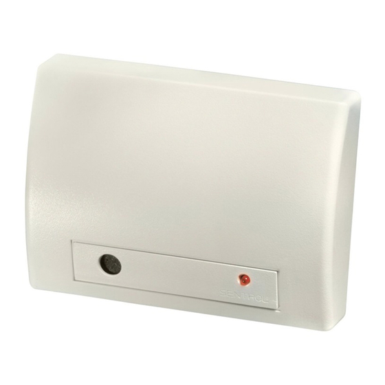
Figure 1. General View
1.1 Acoustic Sensor
The acoustic sensor module of the MCT-501 is omni-directional,
providing 360° coverage. Coverage is measured from the sensor
to the point on the glass farthest from the sensor (see Fig. 3). The
sensor can be mounted as close as 1 m (3.3 ft) from the glass.
Figure 3. Typical Range Measurement
2 2 2 2 . SPECIFICATIONS
. SPECIFICATIONS
. SPECIFICATIONS
. SPECIFICATIONS
ACOUSTIC SENSOR SECTION
Microphone: Omni-directional electret
Alarm Duration: 4 seconds
RF immunity: 20 V/m, 1 MHz to 1000 MHz
Temperature range: -10° to 50°C (14° to 120°F)
Recommended Glass Size:
Minimum: 0.3 x 0.6 m (1 x 2') or larger glass thickness
Plate: 2.4 to 6.4 mm (3/32 to 1/4")
Tempered: 3.2 to 6.4 mm (1/8 to 1/4")
Wired: 6.4 mm (1/4")
Laminated: 3.2 to 6.4 mm (1/8" to 1/4")
POWERCODE TRANSMITTER SECTION
Frequency (MHz): 315, 404, 418, 433.92, 868.95, 869.025,
869.2625 or other frequencies according to local requirements.
Transmitter's ID Code: 24-bit digital word, over 16 million
combinations, pulse width modulation.
Overall Message Length: 36 bits
Message Repetition: One-shot transmission (default) or once
every 3 minutes.
Supervision: Signaling at 60-minute intervals (U.S. version) or 15
minute interval (UK version), or according to the local standards.
Response to Tamper Event: Tamper report every 3 minutes
(until the tamper switch is restored).
DE3596
Figure 2. Module Identification
Installation Instructions
When mounted on opposite wall or adjoining walls, the range is
6 m (20 ft) for plate, tempered, laminated and wired glass.
When mounted on the ceiling, the maximum range is 6 m (20 ft)
for plate, tempered, laminated and wired glass
For armor-coated glass, mount the sensor no more than 3.65 m
(12 ft) from the glass.
1.2 PowerCode Transmitter
The acoustic sensor shares its housing with a miniature
transmitter which has a unique 24-bit PowerCode ID, selected in
the factory from over 16 million possible code combinations.
Upon alarm (glass break detection), a digital message is
transmitted, composed of the PowerCode ID followed by various
status and message-type markers. Alarm and other data are thus
forwarded to the wireless alarm control panel.
Since transmitted messages might collide with transmissions
from other PowerCode transmitters used in the system, a smart
anti-collision transmission sequence is used.
The MCT-501 is protected by a tamper switch that is activated
when the cover is removed. In a tamper situation, a message is
transmitted with the "tamper alert" marker ON.
A periodic supervision message, distinguished by a specific
marker, is transmitted automatically once in 60 minutes. The
wireless control panel is thus informed, at regular intervals, of the
sensor's active participation in the system.
A red LED mounted on the transmitter PCB (visible only when the
cover is off) lights whenever alarm or tamper events are reported.
The LED does not light while a supervision message is being
transmitted.
Operating power is obtained from an on-board 3.6 V Lithium
Thionyl Chloride battery. A weak battery will cause a "low battery"
marker to be added to any message transmitted.
POWER SUPPLY
Power Source: 3.6 V Lithium Thionyl Chloride (LiSOCl2) battery,
size 1/2 AA, Tadiran TL-5902 or equivalent.
Nominal Battery Capacity: 1.2 Ah
Current Drain: 24 µA standby, 13 mA on alarm (including LED)
Battery Life (with LED on):
@ 10 transmissions per day: Over 10 years
@ 50 transmissions per day: About 6 years
Battery Supervision: Automatic transmission of battery condition data
as part of any status report.
PHYSICAL
Operating Temperature: 0°C to 49°C (32°F to 120°F).
Dimensions: 80 x 108 x 43 mm (3.13 x 4.24 x 1.70 in.).
Weight (less battery) : 130 g (4.6 oz)
Housing Material and Color: Flame retardant ABS, white
Compliance with Standards: Meets FCC Part 15, MPT1349
Directive 1999/5/EC
This device complies with the essential requirements and
provisions of Directive 1999/5/EC of the European Parliament and
of the Council of 9 March 1999 on radio and telecommunications
terminal equipment.
and
1
Advertisement

Related Manuals for Visonic MCT-501


Summary of Contents for Visonic MCT-501
- Page 1 1.1 Acoustic Sensor The MCT-501 is protected by a tamper switch that is activated The acoustic sensor module of the MCT-501 is omni-directional, when the cover is removed. In a tamper situation, a message is providing 360°...
- Page 2 Figure 5. Inside View window frames. Do Not Install In Humid Rooms The Wireless MCT-501 is not hermetically sealed. Excess moisture on the circuit board can eventually cause a short and a false alarm.
- Page 3 In order adequate coverage. It is very rare that the sensor will not to test the MCT-501, a test mode is used. With the sensor in the activate within its stated range of coverage. Double check test mode, processing of the glass-break pattern in the upper and adequate battery strength in the hand-held tester.
- Page 4 VISONIC LTD. (ISRAEL): P.O.B 22020 TEL-AVIV 61220 ISRAEL. PHONE: (972-3) 645-6789, FAX: (972-3) 645-6788 VISONIC INC. (U.S.A.): 10 NORTHWOOD DRIVE, BLOOMFIELD CT. 06002-1911. PHONE: (860) 243-0833, (800) 223-0020 FAX: (860) 242-8094 VISONIC LTD. (UK): FRASER ROAD, PRIORY BUSINESS PARK, BEDFORD MK44 3WH. PHONE: (0870) 730-0800 FAX: (0870) 730-0801 www.visonic.com...