Table of Contents
Advertisement
Quick Links
Download this manual
See also:
User Manual
Advertisement
Table of Contents

Related Manuals for Supermicro X11QPH+


Summary of Contents for Supermicro X11QPH+
- Page 1 X11QPH+ USER’S MANUAL Revision 1.0...
- Page 2 State of California, USA. The State of California, County of Santa Clara shall be the exclusive venue for the resolution of any such disputes. Supermicro's total liability for all claims will not exceed the price paid for the hardware product.
-
Page 3: About This Manual
NMVe support. This motherboard is intended to be installed and serviced by professional technicians only. For processor/memory updates, please refer to our website at http://www. supermicro.com/products/. * UPI/memory speeds are dependent on the processors installed in your system. Chapter 1 describes the features, specifications and performance of the motherboard, and provides detailed information on the Intel C621 PCH chip. -
Page 4: Conventions Used In The Manual
Super X11QPH+ User's Manual Conventions Used in the Manual Special attention should be given to the following symbols for proper installation and to prevent damage done to the components or injury to yourself: Warning! Indicates important information given to prevent equipment/property damage or per- sonal injury. -
Page 5: Contacting Supermicro
Super Micro Computer, Inc. 980 Rock Ave. San Jose, CA 95131 U.S.A. Tel: +1 (408) 503-8000 Fax: +1 (408) 503-8008 Email: marketing@supermicro.com (General Information) support@supermicro.com (Technical Support) Website: www.supermicro.com Europe Address: Super Micro Computer B.V. Het Sterrenbeeld 28, 5215 ML... -
Page 6: Table Of Contents
Super X11QPH+ User's Manual Table of Contents Chapter 1 Introduction 1.2 Processor and Chipset Overview ..................19 1.3 Special Features ........................19 1.4 System Health Monitoring ....................20 1.5 ACPI Features ........................20 1.6 Power Supply ........................21 1.7 Super I/O ..........................21 1.8 Advanced Power Management ..................21 Intel Intelligent Power Node Manager (IPNM)..............21 ®... - Page 7 Table of Contents 2.7 Connectors .........................48 Power Supply Unit Connectors ..................48 Fan Headers ........................49 2.7 Jumper Settings .........................54 How Jumpers Work ......................54 2.8 LED Indicators ........................60 Chapter 3 Troubleshooting 3.1 Troubleshooting Procedures ....................63 3.2 Technical Support Procedures ...................67 3.3 Frequently Asked Questions ....................68 3.4 Battery Removal and Installation ..................69 Battery Removal ........................69 Proper Battery Disposal ....................69...
- Page 8 Super X11QPH+ User's Manual Notes...
-
Page 9: Chapter 1 Introduction
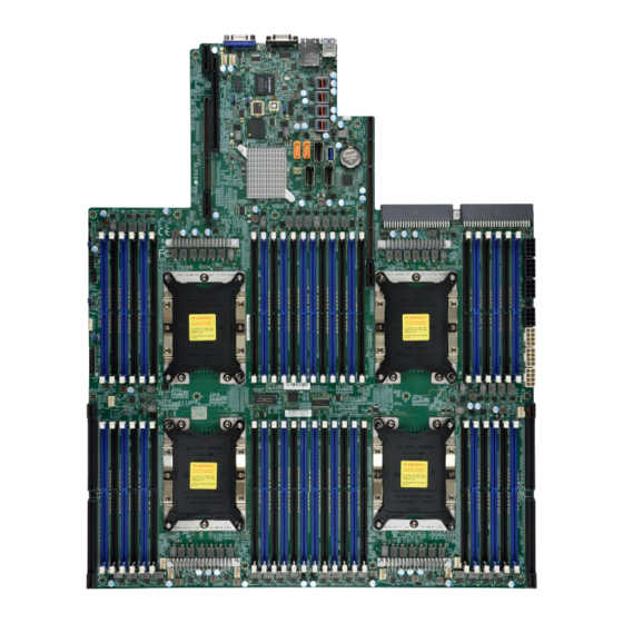
• Product safety info: http://www.supermicro.com/about/policies/safety_information.cfm • If you have any questions, please contact our support team at: support@supermicro.com This manual may be periodically updated without notice. Please check the Supermicro website for possible updates to the manual revision level. - Page 10 Super X11QPH+ User's Manual Figure 1-1. X11QPH+ Motherboard Image Note: All graphics shown in this manual were based upon the latest PCB revision available at the time of publication of the manual. The motherboard you received may or may not look exactly the same as the graphics shown in this manual.
- Page 11 Chapter 1: Introduction Figure 1-2. X11QPH+ Motherboard Layout (not drawn to scale) COM1 IPMI_LAN USB 2/3(3.0) JUSB3 JPCIE1 BMC_HB _LED1 CPLD BIOS JSTBY1 JBT1 I-SATA4~7 JUSB1 SXB2 JBAT1 S-SATA0~3 I-SATA0~3 PSU2 PSU1 CPU1 CPU2 IPMI CODE X11QPH+ BIOS REV.1.01 BAR CODE LICENSE CPU3 CPU4...
-
Page 12: Quick Reference
Super X11QPH+ User's Manual Quick Reference JUIDB1 IPMI_LAN USB2/3(3.0) COM1 WIO x8 COM1 SXB1A IPMI_LAN USB 2/3(3.0) JUSB3 JPG1 S-SATA4 S-SATA5 JPCIE1 JWD1 I-SATA4-7 SXB1B BMC_HB USB4 _LED1 WIO 2x16 CPLD BIOS JSTBY1 JSTBY1 BMC_HB_LED Ultra IOx40 JBT1 JBT1 I-SATA4~7 JUSB1 JSD2 SXB3A... -
Page 13: Jumper Description
Chapter 1: Introduction Quick Reference Table Jumper Description Default Setting Power-Failure Throttling Enable Pins 1-2 (Normal) JBT1 CMOS Clear Open (Normal) JPG1 VGA Enable/Disable Pins 1-2 (Enabled) JPME1 Manufacturing Mode Select Pins 1-2 (Normal) JWD1 Watch Dog Enable Pins 1-2 (Reset) Connector Description JBAT1... - Page 14 Super X11QPH+ User's Manual Description Status BMC_HB_LED1 BMC Heartbeat LED Blinking Green: BMC Normal LED1 UID LED Solid Blue: Unit Identified LED2 Onboard Power LED Solid Green: Power On...
- Page 15 DIMM Size • Up to 128 GB at 1.2V Note 1: Memory speed support depends on the processors used in the system. Note 2: For the latest CPU/memory updates, please refer to our website at http://www.supermicro.com/products/ motherboard. Chipset • Intel C621 PCH Expansion Slots WIO 2x16 (PCI-E 3.0) slot (for CPU2 Port1/ CPU2 Port2) (J18/J19/J20)
- Page 16 Main switch override mechanism • Power-on mode for AC power recovery • Intel® Intelligent Power Node Manager 3.0 (available when the Supermicro Power Manager [SPM] is installed and a special power supply is used • Management Engine (ME) System Health Monitoring •...
- Page 17 User's Guide available at http://www.supermicro.com/support/manuals/. Note 3: It is strongly recommended that you change BMC log-in information upon initial system power-on. The manufacture default username is ADMIN and the password is ADMIN. For proper BMC configuration, please refer to http://www.supermicro.com/ products/info/files/IPMI/Best_Practices_BMC_Security.pdf...
-
Page 18: System Block Diagram
Super X11QPH+ User's Manual Figure 1-3. System Block Diagram X40 ULTRA IO JLAN1 JLAN1 JVGA1 JCOM1 Dedicated X32 WIO X8 WIO in X16 Slot VGA CONN SSATA0, gen3 RTL 8211F LAN Connector CPU1 PE3 x8 SSATA1, gen3 SSATA2, gen3 SSATA3, gen3 AST2500A2 SSATA4, gen3 eSPI... -
Page 19: Processor And Chipset Overview
Chapter 1: Introduction 1.2 Processor and Chipset Overview Built upon the functionality and capability of the Intel Xeon 81xx/61xx/51xx series processors (Socket P0) and the Intel C621 chipset, the X11QPH+ motherboard provides superb system performance, efficient power management, and a rich feature set based on cutting edge technology to address the needs of next-generation computer users. -
Page 20: System Health Monitoring
Super X11QPH+ User's Manual 1.4 System Health Monitoring This section describes the health monitoring features of the X11QPH+ motherboard. The motherboard has an onboard Baseboard Management Controller (AST 2500) that supports system health monitoring. Once a voltage becomes unstable, a warning is given or an error message is sent to the screen. -
Page 21: Power Supply
Intelligent Power Node Manager (IPNM) ® Available when the Supermicro Power Manager (SPM) is installed, Intel's Intelligent Power Node Manager (IPNM) provides your system with real-time thermal control and power management for maximum energy efficiency. Although IPNM Specification Version 2.0/3.0 is supported by the BMC (Baseboard Management Controller), your system must also have IPNM-compatible Management Engine (ME) firmware installed to use this feature. -
Page 22: Management Engine (Me)
Super X11QPH+ User's Manual Management Engine (ME) The Management Engine, which is an ARC controller embedded in the IOH (I/O Hub), provides Server Platform Services (SPS) to your system. The services provided by SPS are different from those provided by the ME on client platforms. -
Page 23: Chapter 2 Installation
Chapter 2: Installation Chapter 2 Installation 2.1 Static-Sensitive Devices Electrostatic Discharge (ESD) can damage electronic com ponents. To avoid damaging your motherboard and your system, it is important to handle it very carefully. The following measures are generally sufficient to protect your equipment from ESD. Precautions •... -
Page 24: Motherboard Installation
Super X11QPH+ User's Manual 2.2 Motherboard Installation All motherboards have standard mounting holes to fit different types of chassis. Make sure that the locations of all the mounting holes for both the motherboard and the chassis match. Although a chassis may have both plastic and metal mounting fasteners, metal ones are highly recommended because they ground the motherboard to the chassis. -
Page 25: Installing The Motherboard
Chapter 2: Installation Installing the Motherboard 1. Install the I/O shield into the back of the chassis. 2. Locate the mounting holes on the motherboard. See the previous page for the location. 3. Locate the matching mounting holes on the chassis. Align the mounting holes on the motherboard against the mounting holes on the chassis. -
Page 26: Processor And Heatsink Installation
CPU socket cap is in place and that none of the socket pins are bent; otherwise, contact your retailer immediately. • Refer to the Supermicro website for updates on CPU support. • Please follow the instructions given in the ESD Warning section on the first page of this chapter before handling, installing, or removing system components. -
Page 27: Overview Of The Processor Socket Assembly
Chapter 2: Installation Overview of the Processor Socket Assembly The processor socket assembly contains 1) the Intel 81xx/61xx/51xx series processor (See the notes below), 2) the narrow processor clip, 3) the dust cover, and 4) the CPU socket. 1. The 81xx/61xx/51xx series processor 81xx/61xx/51xx series (The Processor)-(Non-F Model Only) -
Page 28: Overview Of The Processor Heatsink Module (Phm)
Super X11QPH+ User's Manual Overview of the Processor Heatsink Module (PHM) The Processor Heatsink Module (PHM) contains 1) a heatsink, 2) a narrow processor clip, and 3) the 81xx/61xx/51xx series processor (*non-F model only). 1. Heatsink 2. Narrow processor clip 3. -
Page 29: Attaching The Non-F Model Processor To The Narrow Processor Clip To Create The Processor Package Assembly
Chapter 2: Installation Attaching the Non-F Model Processor to the Narrow Processor Clip to Create the Processor Package Assembly To properly install the CPU into the narrow processor clip, please follow the steps below. 1. Locate pin 1 (notch A), which is the triangle located on the top of the narrow processor clip. -
Page 30: Attaching The Non-F Model Processor Package Assembly To The Heatsink To Form The Processor Heatsink Module (Phm)
Super X11QPH+ User's Manual Attaching the Non-F Model Processor Package Assembly to the Heatsink to Form the Processor Heatsink Module (PHM) After you have made a processor package assembly by following the instructions on the previous page, please follow the steps below to mount the processor package assembly onto the heatsink to create the Processor Heatsink Module (PHM). -
Page 31: Preparing The Cpu Socket For Installation
Chapter 2: Installation Preparing the CPU Socket for Installation This motherboard comes with the CPU socket pre-assembled in the factory. The CPU socket contains 1) a dust cover, 2) a socket bracket, 3) the CPU (P0) socket, and 4) a back plate. These components are pre-installed on the motherboard before shipping. -
Page 32: Installing The Processor Heatsink Module (Phm)
Super X11QPH+ User's Manual Installing the Processor Heatsink Module (PHM) 1. Once you have assembled the processor heatsink module (PHM) by following the instructions listed on page 29 or page 30, you are ready to install the processor heatsink module (PHM) into the CPU socket on the motherboard. To install the PHM into the CPU socket, follow the instructions below. -
Page 33: Removing The Processor Heatsink Module (Phm) From The Motherboard
Chapter 2: Installation Removing the Processor Heatsink Module (PHM) from the Motherboard Before removing the processor heatsink module (PHM), unplug power cord from the power outlet. 1. Using a T30 Torx-bit screwdriver, turn the screws on the PHM counterclockwise to loosen them from the socket, starting with screw marked #4 (in the sequence of 4, 3, 2, 2. -
Page 34: Memory Support And Installation
Super X11QPH+ User's Manual 2.4 Memory Support and Installation Note: Check the Supermicro website for recommended memory modules. Important: Exercise extreme care when installing or removing DIMM modules to pre- vent any damage. Memory Support The motherboard supports up to 6TB of DDR4 3DS LRDIMM/LRDIMM/RDIMM ECC (288- pin) 2666/2400/2133 MHz modules in 48 slots. -
Page 35: Dimm Population Requirements For The 81Xx/61Xx/51Xx Series Processors
Chapter 2: Installation DIMM Population Requirements for the 81xx/61xx/51xx series Processors For optimal memory performance, follow the tables below when populating memory modules. Key Parameters for DIMM Configurations Parameters Possible Values Number of Channels 1, 2, 3, 4, 5, or 6 Number of DIMMs per Channel 1DPC (1 DIMM Per Channel) or 2DPC (2 DIMMs Per Channel) DIMM Type... - Page 36 Super X11QPH+ User's Manual (DDR4 Only) Socket Level Population Requirements DDR4 Socket Level Minimum Population Requirements • There should be at least one DDR4 DIMM per socket. • If only one DIMM is populated in a channel, then populate it in the slot furthest away from CPU. •...
- Page 37 Chapter 2: Installation (DDR4 Only) 2SPC Memory Configuration with x4 DIMMs Total # of DDR Channel Number Adaptive Virtual DIMMs of Ranks Lock Step DIMM Popula- 1 x4 DIMM Must be installed on iMC0 DDR Channel 0 Y, only Bank VLS tion within an >1 Note: Uniformly...
-
Page 38: Dimm Installation
Super X11QPH+ User's Manual DIMM Installation COM1 IPMI_LAN USB 2/3(3.0) JUSB3 1. Insert DIMM modules in the following JPCIE1 order: P1-DIMMA1, P1-DIMMA2, BMC_HB _LED1 CPLD BIOS JSTBY1 then P1-DIMMB1, DIMMB2. For the JBT1 I-SATA4~7 JUSB1 SXB2 system to work properly, please use JBAT1 S-SATA0~3 I-SATA0~3... -
Page 39: Rear I/O Ports
Chapter 2: Installation 2.5 Rear I/O Ports See Figure 2-2 below for the locations and descriptions of the various I/O ports on the rear of the motherboard. COM1 IPMI_LAN USB 2/3(3.0) JUSB3 JPCIE1 BMC_HB _LED1 CPLD BIOS JSTBY1 JBT1 I-SATA4~7 JUSB1 SXB2 JBAT1... - Page 40 Super X11QPH+ User's Manual VGA Port The onboard VGA port is located next to the UID switch on the I/O back panel. Use this connection for VGA display. Serial Port There is one COM port (COM1) next to the IPMI_LAN on the I/O back panel. The COM port provides serial communication support.
- Page 41 Chapter 2: Installation Universal Serial Bus (USB) Ports There are two USB 3.0 ports (USB2/3) on the I/O back panel. A USB header that supports two USB 2.0 connections (USB0/1) are also located on the motherboard to provide front access support.
- Page 42 Note: UID can also be triggered via IPMI on the motherboard. For more information on IPMI, please refer to the IPMI User's Guide posted on our website at http://www. supermicro.com. UID Switch UID LED...
-
Page 43: Front Control Panel
JF1 contains header pins for various buttons and indicators that are normally located on a control panel at the front of the chassis. These connectors are designed specifically for use with Supermicro chassis. See the figure below for the descriptions of the front control panel buttons and LED indicators. - Page 44 Super X11QPH+ User's Manual Power Button The Power Button connection is located on pins 1 and 2 of JF1. Momentarily contacting both pins will power on/off the system. This button can also be configured to function as a suspend button (with a setting in the BIOS - see Chapter 4). To turn off the power when the system is in suspend mode, press the button for 4 seconds or longer.
- Page 45 Chapter 2: Installation Power Fail LED The Power Fail LED connection is located on pins 5 and 6 of JF1. Refer to the table below for pin definitions. Power Fail LED Pin Definitions (JF1) Pin# Definition 3.3V PWR Supply Fail Fan Fail and UID LED Connect an LED cable to pins 7 and 8 of the Front Control Panel to use the Overheat/Fan Fail LED connections.
- Page 46 Super X11QPH+ User's Manual NIC1/NIC2 (LAN1/LAN2) The NIC (Network Interface Controller) LED connection for LAN port 1 is located on pins 11 and 12 of JF1, and LAN port 2 is on pins 9 and 10. Attach the NIC LED cables here to display network activity.
-
Page 47: Nmi Button
Chapter 2: Installation Power LED The Power LED connection is located on pins 15 and 16 of JF1. Refer to the table below for pin definitions. Power LED Pin Definitions (JF1) Pins Definition 3.3V PWR LED NMI Button The non-maskable interrupt (NMI) button header is located on pins 19 and 20 of JF1. Refer to the table below for pin definitions. -
Page 48: Connectors
Super X11QPH+ User's Manual 2.7 Connectors Power Supply Unit Connectors Power Supply Unit Connectors Two main power supply unit connectors (PSU1/PSU2) are located on J24/J25 on the motherboard. Connect these connectors to your power supply to provide power to your system. -
Page 49: Fan Headers
Chapter 2: Installation Fan Headers Onboard Fan Header This motherboard has ten fan headers (FAN1~FAN10) used for CPU/system cooling. These are all 4-pin fan headers, which are backward compatible with a traditional 3-pin fan. The onboard fan speed is controlled by Thermal Management (via Hardware Monitoring) in the BIOS. - Page 50 Super X11QPH+ User's Manual TPM Header The JTPM1 header is used to connect a Trusted Platform Module (TPM)/Port 80, which is available from a third-party vendor. TPM/Port 80 is a security device which supports encryption and authentication in hard drives. It allows the motherboard to deny access if the TPM associated with the hard drive is not installed in the system.
-
Page 51: Chassis Intrusion
Chapter 2: Installation Standby Power The Standby Power header is located at JSTBY1 on the motherboard. You must have a card with a Standby Power connector and a cable to use this feature. Refer to the table below for pin definitions. Standby Power Pin Definitions Pin#... - Page 52 Super X11QPH+ User's Manual SATA Power Connectors The SATA power connectors at JSD1 and JSD2 provide 5V power to onboard SATA devices. Refer to the table below for pin definitions. SATA Power Pin Definitions Pin# Definition Ground Ground 1. JSD1 COM1 IPMI_LAN USB 2/3(3.0)
- Page 53 S-SATA4, S-SATA5) on the motherboard. The I-SATA ports are supported by the Intel C621 chipset, and the S-SATA ports are supported by Intel SCU. S-SATA4/S-SATA5 can be used with Supermicro SuperDOMs which are yellow SATA DOM connectors with power pins built in, and do not require external power cables. Supermicro SuperDOMs are backward-compatible with regular SATA HDDs or SATA DOMs that need external power cables.
-
Page 54: Jumper Settings
Super X11QPH+ User's Manual 2.7 Jumper Settings How Jumpers Work To modify the operation of the motherboard, jumpers can be used to choose between optional settings. Jumpers create shorts between two pins to change the function of the connector. Pin 1 is identified with a square solder pad on the printed circuit board. See the diagram at right for an example of jumping pins 1 and 2. - Page 55 Chapter 2: Installation CMOS Clear JBT1 is used to clear CMOS, which will also clear any passwords. Instead of pins, this jumper consists of contact pads to prevent accidentally clearing the contents of CMOS. To Clear CMOS 1. First power down the system and unplug the power cord(s). 2.
- Page 56 Super X11QPH+ User's Manual Power-Failure Throttling Enable/Disable The Power-Failure Throttling jumper is located at J17. Close pins 1-2 of J17 to enable power throttling feature. The default setting is the close pins 2-3 for normal operation. See the jumper setting table below. Power-Failure Throttling Jumper Settings Jumper Setting...
- Page 57 Chapter 2: Installation Management Engine (ME) Recovery Use jumper JPME1 to select ME Firmware Recovery mode, which will limit resource allocation for essential system operation only in order to maintain normal power operation and management. In the single operation mode, online upgrade will be available via Recovery mode.
- Page 58 Super X11QPH+ User's Manual Watch Dog JWD1 controls the Watch Dog function. Watch Dog is a monitor that can reboot the system when a software application hangs. Jumping pins 1-2 will cause Watch Dog to reset the system if an application hangs. Jumping pins 2-3 will generate a non-maskable interrupt signal for the application that hangs.
- Page 59 Chapter 2: Installation VGA Enable/Disable JPG1 allows you to enable or disable the VGA port, which is supported by the onboard BMC controller. The default setting is Enabled. VGA Enable/Disable Jumper Settings Jumper Setting Definition Pins 1-2 Enabled Pins 2-3 Disabled 1.
-
Page 60: Led Indicators
Super X11QPH+ User's Manual 2.8 LED Indicators IPMI LAN IPMI_LAN LEDs Link LED Activity LED An IPMI-dedicated LAN, supported by the onboard Baseboard Management IPMI LAN Link LED (Left) & controller, is located on the I/O back panel. Activity LED (Right) The amber LED on the right indicates Color State... - Page 61 Chapter 2: Installation BMC Heartbeat LED BMC_HB_LED1 is the BMC heartbeat LED. When the LED is blinking green, BMC is functioning normally. See the table below for the LED status. Onboard Power LED Indicator LED Color Definition Green: BMC Normal Blinking Onboard Power LED The Onboard Power LED is located at LED2 on the motherboard.
- Page 62 Super X11QPH+ User's Manual Unit ID LED A rear UID LED indicator (LED1) is located near the UID switch on the I/O back panel. This UID indicator provides easy identification of a system.unit that may need service. UID LED LED Indicator LED Color Definition Blue: On...
-
Page 63: Chapter 3 Troubleshooting
Chapter 3: Troubleshooting Chapter 3 Troubleshooting 3.1 Troubleshooting Procedures Use the following procedures to troubleshoot your system. If you have followed all of the procedures below and still need assistance, refer to the ‘Technical Support Procedures’ and/ or ‘Returning Merchandise for Service’ section(s) in this chapter. Always disconnect the AC power cord before adding, changing or installing any non hot-swap hardware components. -
Page 64: System Boot Failure
Super X11QPH+ User's Manual No Video 1. If the power is on but you have no video, remove all the add-on cards and cables. 2. Use the speaker to determine if any beep codes exist. Refer to Appendix A for details on beep codes. -
Page 65: When The System Becomes Unstable
2. Memory support: Make sure that the memory modules are supported by testing the modules using memtest86 or a similar utility. Note: Refer to the product page on our website at http:\\www.supermicro.com for memory and CPU support and updates. 3. HDD support: Make sure that all hard disk drives (HDDs) work properly. Replace the bad HDDs with good ones. - Page 66 Super X11QPH+ User's Manual 3. Using the minimum configuration for troubleshooting: Remove all unnecessary components (starting with add-on cards first), and use the minimum configuration (but with a CPU and a memory module installed) to identify the trouble areas. Refer to the steps listed in Section A above for proper troubleshooting procedures.
-
Page 67: Technical Support Procedures
Chapter 3: Troubleshooting 3.2 Technical Support Procedures Before contacting Technical Support, please take the following steps. Also, note that as a motherboard manufacturer, we do not sell directly to end-users, so it is best to first check with your distributor or reseller for troubleshooting services. They should know of any possible problem(s) with the specific system configuration that was sold to you. -
Page 68: Frequently Asked Questions
Updated BIOS files are located on our website at http://www. supermicro.com. Please check our BIOS warning message and the information on how to update your BIOS on our website. Select your motherboard model and download the BIOS file to your computer. -
Page 69: Battery Removal And Installation
Chapter 3: Troubleshooting 3.4 Battery Removal and Installation Battery Removal To remove the onboard battery, follow the steps below: 1. Power off your system and unplug your power cable. 2. Locate the onboard battery as shown below. 3. Using a tool such as a pen or a small screwdriver, push the battery lock outwards to unlock it. -
Page 70: Returning Merchandise For Service
Shipping and handling charges will be applied for all orders that must be mailed when service is complete. For faster service, RMA authorizations may be requested online (http://www.supermicro.com/ support/rma/). This warranty only covers normal consumer use and does not cover damages incurred in shipping or from failure due to the alteration, misuse, abuse or improper maintenance of products. -
Page 71: Chapter 4 Bios
Chapter 4: BIOS Chapter 4 BIOS 4.1 Introduction This chapter describes the AMIBIOS™ Setup utility for theX11QPH+ motherboard. The BIOS is stored on a chip and can be easily upgraded using a flash program. Note: Due to periodic changes to the BIOS, some settings may have been added or deleted and might not yet be recorded in this manual. -
Page 72: Main Setup
Note: The time is in the 24-hour format. For example, 5:30 P.M. appears as 17:30:00. The date's default value is 01/01/2014 after RTC reset. Supermicro X11QPH+ BIOS Version This item displays the version of the BIOS ROM used in the system. - Page 73 Chapter 4: BIOS Memory Information Total Memory This item displays the total size of memory available in the system. Memory Speed This item displays the default speed of the memory modules installed in the system.
-
Page 74: Advanced Setup Configurations
Super X11QPH+ User's Manual 4.3 Advanced Setup Configurations Use the arrow keys to select the Advanced submenu and press <Enter> to access the submenu items: Warning: Take Caution when changing the Advanced settings. An incorrect value, an incorrect DRAM frequency, or an incorrect BIOS timing setting may cause the system to malfunction. When this occurs, restore the setting to the manufacture default setting. -
Page 75: Power Configuration
Chapter 4: BIOS Wait For 'F1' If Error Select Enabled to force the system to wait until the 'F1' key is pressed if an error occurs. The options are Disabled and Enabled. Interrupt 19 Trap Capture Interrupt 19 is the software interrupt that handles the boot disk function. When this item is set to Immediate, the ROM BIOS of the host adaptors will "capture"... -
Page 76: Cpu Configuration
Super X11QPH+ User's Manual CPU Configuration Warning: Setting the wrong values in the features below may cause the system to malfunction. Processor Configuration The following CPU information will be displayed: • Processor BSP Revision • Processor Socket • Processor ID •... - Page 77 Chapter 4: BIOS Hardware Prefetcher (Available when supported by the CPU) If this feature is set to Enable, the hardware prefetcher will prefetch streams of data and instructions from the main memory to the Level 2 (L2) cache to improve CPU performance. The options are Disable and Enable.
-
Page 78: Advanced Power Management Configuration
Super X11QPH+ User's Manual Advanced Power Management Configuration CPU P State Control SpeedStep (PStates) EIST (Enhanced Intel SpeedStep Technology) allows the system to automatically adjust processor voltage and core frequency in an effort to reduce power consumption and heat dissipation. -
Page 79: Chipset Configuration
Chapter 4: BIOS Enhanced Halt State (C1E) Select Enable to enable "Enhanced Halt State" support, which will significantly reduce the CPU's power consumption by minimizing CPU's clock cycles and reduce voltage during a "Halt State." The options are Disable and Enable. Package C State Control ... -
Page 80: Memory Configuration
Super X11QPH+ User's Manual Link L0p Enable Select Enable to enable Link L0p. The options are Disable, Enable, and Auto. Link L1 Enable Select Enable to enable Link L1 (Level 1 link). The options are Disable, Enable, and Auto. IO Directory Cache Select Enable for the IODC (I/O Directory Cache) to generate snoops instead of generating memory lockups for remote IIO (InvIToM) and/or WCiLF (Cores). - Page 81 Chapter 4: BIOS Enable ADR Select Enable for ADR (Automatic Diagnostic Repository) support to enhance memory performance. The options are Enable and Disable. Memory Topology This item displays the information of onboard memory modules as detected by the BIOS. •...
-
Page 82: Iio Configuration
Super X11QPH+ User's Manual SDDC Plus One Select Enable for SDDC (Single Device Data Correction) Plus One support, which will increase the reliability and serviceability of your system memory. The options are Enable and Disable. ADDDC (Adaptive Double Device Data Correction) Sparing Select Enable for ADDDC sparing support to enhance memory performance. - Page 83 Chapter 4: BIOS MCP1 (IIO PCIe Br5) This feature configures the PCI-E Bifuraction setting for a PCI-E port specified by the user. The options are x16 and Auto. Socket 0 PCI-E Br0D00F0 - Port 0/DMI (Available for CPU 1 Configuration ...
- Page 84 Super X11QPH+ User's Manual PCI-E Completion Timeout Disable Select Enable to enable PCI-E Completion Timeout support. The options are Enable and Disable. PCI-E Completion Timeout Value This feature allows the user to set the PCI-E Completion Timeout value. The default setting is 260ms to 900ms.
- Page 85 Chapter 4: BIOS PCI-E Completion Timeout Value This feature allows the user to set the PCI-E Completion Timeout value. The default setting is 260ms to 900ms. Sck3 (Socket 3) RP (Root-Port) Correctable Err (Errors) Select Enable to enable interrupt on correctable errors occur on a root port. The default setting is Disable.
- Page 86 Super X11QPH+ User's Manual Relaxed Ordering Select Enable to enable Relaxed Ordering support which will allow certain transactions to violate the strict-ordering rules of PCI and to be completed prior to other transactions that have already been enqueued. The options are Disable and Enable. Intel®...
- Page 87 Chapter 4: BIOS Intel® VMD Technology Intel® VMD for Onboard NVMe Intel® VMD for Volume Management D Select Enable to enable Intel Volume Management Device Technology in the stack. The default setting is Disable. Onboard NVMe Mode Select Enable to enable onboard NVME mode support. The default setting is Disable. Intel®...
-
Page 88: South Bridge
Super X11QPH+ User's Manual PCI-E Completion Timeout (Global) Select Yes to disable the PCI-E Completion Time-out settings. The options are Yes, No, and Per-Port. South Bridge The following South Bridge information will display: • USB Module Version • USB Devices Legacy USB Support Select Enabled to support onboard legacy USB devices. - Page 89 Chapter 4: BIOS (PCH) SATA Configuration When this submenu is selected, the AMI BIOS automatically detects the presence of the SATA devices that are supported by the Intel PCH chip and displays the following items: SATA Controller This item enables or disables the onboard SATA controller supported by the Intel PCH chip. The options are Enable and Disable.
- Page 90 Super X11QPH+ User's Manual SATA Device Type Use this item to specify if the device installed on the SATA port selected by the user should be connected to a Solid State drive or a Hard Disk Drive. The options are Hard Disk Drive and Solid State Drive.
- Page 91 Chapter 4: BIOS Spin Up Device On an edge detect from 0 to 1, set this item to allow the sSATA device installed on the sSATA port specified by the user to start a COMRESET initialization. The options are Enable and Disable. sSATA Device Type Use this item to specify if the device installed on the sSATA port specified by the user should be connected to a Solid State drive or a Hard Disk Drive.
-
Page 92: Network Stack Configuration
Super X11QPH+ User's Manual MMCFG Base This feature determines the lowest MMCFG (Memory-Mapped Configuration) base assigned to PCI devices. The options are 1G, 1.5G, 1.75G. 2G, 2.25G, and 3G. VGA Priority This feature selects the graphics device to be used as the primary video display for system boot. -
Page 93: Super Io Configuration
Chapter 4: BIOS Super IO Configuration Super IO Chip AST2500 Serial Port 1 Configuration Serial Port Select Enabled to enable the onboard serial port specified by the user. The options are Enabled and Disabled. Device Settings This feature displays the base I/O port address and the Interrupt Request address of a serial port specified by the user. -
Page 94: Serial Port Console Redirection
Super X11QPH+ User's Manual IRQ=3, 4, 5, 6, 7, 9, 10, 11, 12), (IO=2F8h; IRQ=3, 4, 5, 6, 7, 9, 10, 11, 12); (IO=3E8h; IRQ=3, 4, 5, 6, 7, 9, 10, 11, 12), and (IO=2E8h; IRQ=3, 4, 5, 6, 7, 9, 10, 11, 12). Serial Port 2 Attribute Select SOL to use COM Port 2 as a Serial_Over_LAN (SOL) port for console redirection. - Page 95 Chapter 4: BIOS Stop Bits A stop bit indicates the end of a serial data packet. Select 1 Stop Bit for standard serial data communication. Select 2 Stop Bits if slower devices are used. The options are 1 and 2. Flow Control Use this feature to set the flow control for Console Redirection to prevent data loss caused by buffer overflow.
- Page 96 Super X11QPH+ User's Manual Console Redirection Settings (for SOL/COM2) Use this feature to specify how the host computer will exchange data with the client computer, which is the remote computer used by the user. Terminal Type Use this feature to select the target terminal emulation type for Console Redirection. Select VT100 to use the ASCII Character set.
- Page 97 Chapter 4: BIOS Recorder Mode Select Enabled to capture the data displayed on a terminal and send it as text messages to a remote server. The options are Disabled and Enabled. Resolution 100x31 Select Enabled for extended-terminal resolution support. The options are Disabled and Enabled.
-
Page 98: Acpi Settings
Super X11QPH+ User's Manual EMS Console Redirection Settings Out-of-Band Management Port The feature selects a serial port in a client server to be used by the Windows Emergency Management Services (EMS) to communicate with a remote host server. The options are COM1 (Console Redirection) and COM2/SOL (Console Redirection). - Page 99 Chapter 4: BIOS High Precision Timer Select Enabled to activate the High Precision Event Timer (HPET) that produces periodic interrupts at a much higher frequency than a Real-time Clock (RTC) does in synchronizing multimedia streams, providing smooth playback and reducing the dependency on other timestamp calculation devices, such as an x86 RDTSC Instruction embedded in the CPU.
- Page 100 "IIO Configuration" in the "Chipset/North Bridge" submenu). Note 2: For more information on TPM, please refer to the TPM manual at http://www. supermicro.com/manuals/other. Intel® Virtual RAID on CPU When this submenu is selected and the RAID devices are detected, the BIOS screen displays the following items: Intel®...
-
Page 101: Event Logs
Chapter 4: BIOS 4.4 Event Logs Use this feature to configure Event Log settings. Change SMBIOS Event Log Settings Enabling/Disabling Options SMBIOS Event Log Select Enabled to enable SMBIOS (System Management BIOS) Event Logging during system boot. The options are Enabled and Disabled. Erasing Settings Erase Event Log Select Enabled to erase all error events in the SMBIOS (System Management BIOS) log... -
Page 102: Customer Options
Super X11QPH+ User's Manual SMBIOS Event Log Standard Settings Log System Boot Event Select Enabled to log system boot events. The options are Enabled and Disabled. MECI (Multiple Event Count Increment) Enter the increment value for the multiple event counter. Enter a number between 1 to 255. The default setting is 1. -
Page 103: Ipmi
Chapter 4: BIOS 4.5 IPMI Use this feature to configure Intelligent Platform Management Interface (IPMI) settings. When you select this submenu and press the <Enter> key, the following information will display: • IPMI Firmware Revision: This feature indicates the IPMI firmware revision used in your system. -
Page 104: Bmc Network Configuration
Super X11QPH+ User's Manual When SEL is Full This feature allows the user to determine what the BIOS should do when the system event log is full. Select Erase Immediately to erase all events in the log when the system event log is full. - Page 105 Chapter 4: BIOS IPMI LAN Selection Use this feature to configure the IPMI LAN mode setting. The options are Dedicated, Shared, and Failover. VLAN Support Select Enabled for IPMI VLAN support. The options are Disabled and Enabled. Configuration Address Source Use this feature to select the IP address source for this computer.
-
Page 106: Security Settings
Super X11QPH+ User's Manual 4.6 Security Settings This menu allows the user to configure the following security settings for the system. Administrator Password Use this feature to set the administrator password which is required to enter the BIOS setup utility. The length of the password should be from 3 characters to 20 characters long. User Password Use this feature to set the user password which is required to enter the BIOS setup utility. -
Page 107: Key Management
Chapter 4: BIOS Attempt Secure Boot If this feature is set to Enabled, the BIOS will attempt to use secure boot settings for system boot. A Platform Key is a security key used to manage the security settings of the platform firmware used in your system. -
Page 108: Authorized Signatures
Super X11QPH+ User's Manual and the key source of the Key-Exchange-Keys. The options are Save to File, Set New, and Erase. Authorized Signatures This feature allows the user to enter and configure a set of values to be used as Authorized Signatures for the system. -
Page 109: Boot Settings
Chapter 4: BIOS 4.7 Boot Settings Use this feature to configure Boot Settings: Boot Mode Select Use this feature to select the type of devices to be used for system boot. The options are Legacy, UEFI (Unified Extensible Firmware Interface), and Dual. Fixed Boot Order Priorities This feature prioritizes the order of a bootable device from which the system will boot. -
Page 110: Add New Boot Option
Super X11QPH+ User's Manual Add New Boot Option This feature allows the user to add a new boot option to the boot priority features for your system. Add Boot Option Use this feature to specify the name for the new boot option. Path for Boot Option Use this feature to enter the path for the new boot option in the format fsx:\path\filename.efi. - Page 111 Chapter 4: BIOS Delete Drive Option Select the target boot driver to delete from the boot priority list. Hard Disk Drive BBS Priorities • Boot Option #1 - #5 Network Drive BBS Priorities • Boot Option #1 USB Key Drive BBS Priorities •...
-
Page 112: Save & Exit
Super X11QPH+ User's Manual 4.8 Save & Exit Select the Save & Exit tab from the BIOS setup screen to configure the settings below. Save Options Discard Changes and Exit Select this option to quit the BIOS setup without making any permanent changes to the system configuration and reboot the computer. - Page 113 Chapter 4: BIOS Default Options Restore Optimized Defaults To set this feature, select Restore Defaults from the Exit menu and press <Enter> to load manufacturer default settings which are intended for maximum system performance but not for maximum stability. Save As User Defaults To set this feature, select Save as User Defaults from the Exit menu and press <Enter>.
-
Page 114: Appendix A Bios Post Codes
Super X11QPH+ User's Manual Appendix A BIOS POST Codes BIOS Error POST (Beep) Codes During the POST (Power-On Self-Test) routines, which are performed each time the system is powered on, errors may occur. Non-fatal errors are those which, in most cases, allow the system to continue the boot-up process. - Page 115 When BIOS performs the Power On Self Test, it writes checkpoint codes to I/O port 0080h. If the computer cannot complete the boot process, a diagnostic card can be attached to the computer to read I/O port 0080h (Supermicro p/n AOC-LPC80-20). For information on AMI updates, please refer to http://www.ami.com/products/.
-
Page 116: Appendix B Software Installation
Appendix B Software Installation B.1 Installing Software Programs The Supermicro FTP site contains drivers and utilities for your system at ftp://ftp.supermicro. com. Some of these must be installed, such as the chipset driver. After accessing the FTP site, go into the CDR_Images directory and locate the ISO file for your motherboard. -
Page 117: Superdoctor ® 5
SATA settings back to your original settings. B.2 SuperDoctor ® The Supermicro SuperDoctor 5 is a hardware monitoring program that functions in a command-line or web-based interface in Windows and Linux operating systems. The program monitors system health information such as CPU temperature, system voltages, system power consumption, fan speed, and provides alerts via email or Simple Network Management Protocol (SNMP). -
Page 118: Appendix C Standardized Warning Statements
The following statements are industry standard warnings, provided to warn the user of situations which have the potential for bodily injury. Should you have questions or experience difficulty, contact Supermicro's Technical Support department for assistance. Only certified technicians should attempt to install or configure components. - Page 119 Appendix C: Standardized Warning Statements Attention Danger d'explosion si la pile n'est pas remplacée correctement. Ne la remplacer que par une pile de type semblable ou équivalent, recommandée par le fabricant. Jeter les piles usagées conformément aux instructions du fabricant. ¡Advertencia! Existe peligro de explosión si la batería se reemplaza de manera incorrecta.
-
Page 120: Product Disposal
Super X11QPH+ User's Manual Product Disposal Warning! Ultimate disposal of this product should be handled according to all national laws and regulations. 製品の廃棄 この製品を廃棄処分する場合、 国の関係する全ての法律 ・ 条例に従い処理する必要があります。 警告 本产品的废弃处理应根据所有国家的法律和规章进行。 警告 本產品的廢棄處理應根據所有國家的法律和規章進行。 Warnung Die Entsorgung dieses Produkts sollte gemäß allen Bestimmungen und Gesetzen des Landes erfolgen. -
Page 121: Appendix D Uefi Bios Recovery
Warning: Do not upgrade the BIOS unless your system has a BIOS-related issue. Flashing the wrong BIOS can cause irreparable damage to the system. In no event shall Supermicro be liable for direct, indirect, special, incidental, or consequential damages arising from a BIOS update. - Page 122 USB device or a writable CD/DVD. Note: If you cannot locate the "Super.ROM" file in your drive disk, visit our website at www.supermicro.com to download the BIOS package. Extract the BIOS binary image into a USB flash device and rename it "Super.ROM" for the BIOS recovery use.
- Page 123 Appendix D: UEFI BIOS Recovery 3. After locating the healthy BIOS binary image, the system will enter the BIOS Recovery menu as shown below. Note: At this point, you may decide if you want to start the BIOS recovery. If you decide to proceed with BIOS recovery, follow the procedures below.
- Page 124 Super X11QPH+ User Manual 5. After the BIOS recovery process is complete, press any key to reboot the system. 6. Using a different system, extract the BIOS package into a USB flash drive. 7. Press <Del> continuously during system boot to enter the BIOS Setup utility. From the top of the tool bar, select Boot to enter the submenu.
- Page 125 Appendix D: UEFI BIOS Recovery 8. When the UEFI Shell prompt appears, type fs# to change the device directory path. Go to the directory that contains the BIOS package you extracted earlier from Step 6. Enter flash.nsh BIOSname.### at the prompt to start the BIOS update process. Note: Do not interrupt this process until the BIOS flashing is complete.
- Page 126 (Disclaimer Continued) The products sold by Supermicro are not intended for and will not be used in life support systems, medical equipment, nuclear facilities or systems, aircraft, aircraft devices, aircraft/emergency com- munication devices or other critical systems whose failure to perform be reasonably expected to result in significant injury or loss of life or catastrophic property damage.