Table of Contents
Advertisement
Advertisement
Table of Contents

Related Manuals for ASROCK X299 GAMING i9


Summary of Contents for ASROCK X299 GAMING i9
-
Page 2: Copyright Notice
(including damages for loss of profits, loss of business, loss of data, interruption of business and the like), even if ASRock has been advised of the possibility of such damages arising from any defect or error in the documentation or product. - Page 3 If you require assistance please call ASRock Tel : +886-2-28965588 ext.123 (Standard International call charges apply)
- Page 4 Fatal1ty Story Who knew that at age 19, I would be a World Champion PC gamer. When I was 13, I actually played competitive billiards in professional tournaments and won four or five games off guys who played at the highest level. I actually thought of making a career of it, but at that young age situations change rapidly.
- Page 5 LIVIN’ LARGE Since my first big tournament wins, I have been a “Professional Cyberathlete”, traveling the world and livin’ large with lots of International media coverage on outlets such as MTV, ESPN and a 60 Minutes segment on CBS to name only a few. It's unreal - it's crazy. I’m living a dream by playing video games for a living.
-
Page 6: Table Of Contents
Contents Chapter 1 Introduction Package Contents Specifications Motherboard Layout I/O Panel Chapter 2 Installation Installing the CPU Installing the CPU Fan and Heatsink Installation of Memory Modules (DIMM) Expansion Slots (PCI Express Slots) Jumpers Setup Onboard Headers and Connectors Smart Switches Dr. - Page 7 M.2_SSD (NGFF) Module Installation Guide Chapter 3 Software and Utilities Operation Installing Drivers F-Stream 3.2.1 Installing F-Stream 3.2.2 Using F-Stream ASRock Live Update & APP Shop 3.3.1 UI Overview 3.3.2 Apps 3.3.3 BIOS & Drivers 3.3.4 Setting Creative SoundBlaster Cinema3...
- Page 8 4.6.2 Chipset Configuration 4.6.3 Storage Configuration 4.6.4 Super IO Configuration 4.6.5 ACPI Configuration 4.6.6 USB Configuration 4.6.7 Trusted Computing Tools Hardware Health Event Monitoring Screen Security Screen 4.10 Boot Screen 4.11 Exit Screen...
-
Page 9: Chapter 1 Introduction
If you require technical support related to this mother- board, please visit our website for specific information about the model you are using. You may find the latest VGA cards and CPU support list on ASRock’s website as well. ASRock website http://www.asrock.com. -
Page 10: Specifications
933(OC)/2800(OC)/2666/2400/2133 non-ECC, un-buffered memory * The maximum memory frequency supported may vary by processor type. * Please refer to Memory Support List on ASRock’s website for more information. (http://www.asrock.com/) • Supports non-ECC RDIMM (Registered DIMM) • Max. capacity of system memory: 128GB • Supports Intel®... - Page 11 • 7.1 CH HD Audio with Content Protection (Realtek ALC1220 Audio Codec) • Premium Blu-ray Audio support • Supports Surge Protection (ASRock Full Spike Protection) • Nichicon Fine Gold Series Audio Caps • 120dB SNR DAC with Differential Amplifier • TI® NE5532 Premium Headset Amplifier for Front Panel Audio Connector (Supports up to 600 Ohm headsets) • Pure Power-In...
- Page 12 * Ultra USB Power is supported on USB3_12 ports. * ACPI wake-up function is not supported on USB3_12 ports. • 4 x USB 3.0 Ports (Supports ESD Protection (ASRock Full Spike Protection)) • 3 x RJ-45 LAN Ports with LED (ACT/LINK LED and SPEED LED) • 1 x BIOS Flashback Switch...
- Page 13 M.2 PCI Express module up to Gen3 x4 (32 Gb/s)** ** Supports Intel® Optane Technology (on M2_2 and M2_3) ** Supports NVMe SSD as boot disks ** Supports ASRock U.2 Kit Connector • 1 x Virtual RAID On CPU Header • 1 x TPM Header • 1 x Power LED and Speaker Header...
- Page 14 • 2 x USB 2.0 Headers (Support 4 USB 2.0 ports) (Supports ESD Protection (ASRock Full Spike Protection)) • 2 x USB 3.0 Headers (Support 4 USB 3.0 ports) (ASMedia ASM1074 Hub) (Supports ESD Protection (ASRock Full Spike Protection)) • 1 x Front Panel Type C USB 3.1 Header (ASMedia ASM3142) * Supports USB PD 2.0 up to 12V@3A (36W) charging...
- Page 15 • ErP/EuP ready (ErP/EuP ready power supply is required) * For detailed product information, please visit our website: http://www.asrock.com Please realize that there is a certain risk involved with overclocking, including adjusting the setting in the BIOS, applying Untied Overclocking Technology, or using third-party overclocking tools.
-
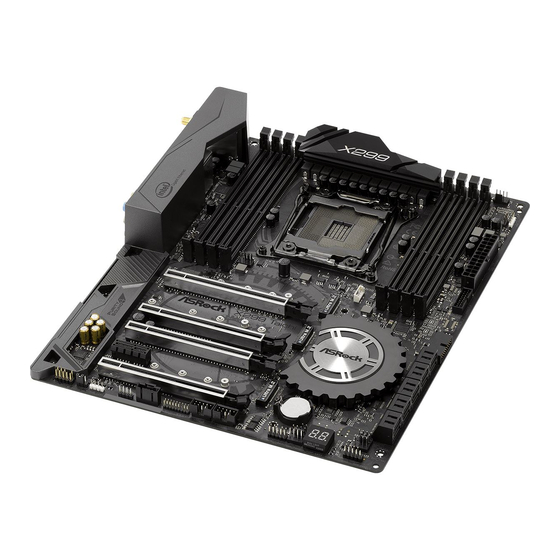
Page 16: Motherboard Layout
Top: T: USB3 RJ-45 B: USB4 USB 3.1 Top: T: USB31_TA_1 RJ-45 B: USB31_TC_1 CHA_FAN2 FATAL VROC1 PCIE1 Intel X299 PCIE2 X299 Gaming i9 PCIE3 PCIE4 AUDIO CODEC SPK_PLED1 Power Reset PCIE5 BIOS_B1 BIOS BIOS_A_LED1 RoHS BIOS_B_LED1 CHA_FAN1 Debug HD_AUDIO1... - Page 17 Fatal1ty X299 Professional Gaming i9 Series No. Description 2 x 288-pin DDR4 DIMM Slots (DDR4_A1, DDR4_B1) 2 x 288-pin DDR4 DIMM Slots (DDR4_A2, DDR4_B2) ATX 12V Power Connector (ATX12V1) CPU Fan / Waterpump Fan Connector (CPU_OPT/W_PUMP) 2 x 288-pin DDR4 DIMM Slots (DDR4_C2, DDR4_D2) 2 x 288-pin DDR4 DIMM Slots (DDR4_C1, DDR4_D1) CPU Fan Connector (CPU_FAN1) RGB LED Header (RGB_LED2)
-
Page 18: I/O Panel
1.4 I/O Panel No. Description No. Description Fatal1ty Mouse Port (USB1) Optical SPDIF Out Port USB 2.0 Port (USB2) USB 3.1 Type-A Port (USB31_TA_1) LAN RJ-45 Port (Intel® I211AT)* USB 3.1 Type-C Port (USB31_TC_1) 10 GLAN RJ-45 Port (AQUANTIA® USB 3.0 Ports (USB3_34) AQC107)** LAN RJ-45 Port (Intel®... - Page 19 Fatal1ty X299 Professional Gaming i9 Series ** There are two LEDs on each LAN port. Please refer to the table below for the LAN port LED indications. ACT/LINK LED SPEED LED LAN Port Activity / Link LED Speed LED Status Description Status Description...
- Page 20 1.5 WiFi-802.11ac Module and ASRock WiFi 2.4/5 GHz Antenna WiFi-802.11ac + BT Module This motherboard comes with an exclusive WiFi 802.11 a/b/g/n/ac + BT v4.0 module (pre-installed on the rear I/O panel) that offers support for WiFi 802.11 a/b/ g/n/ac connectivity standards and Bluetooth v4.0. WiFi + BT module is an easy-to- use wireless local area network (WLAN) adapter to support WiFi + BT.
- Page 21 Fatal1ty X299 Professional Gaming i9 Series WiFi Antennas Installation Guide Step 1 Prepare the WiFi 2.4/5 GHz Antennas that come with the package. Step 2 Connect the two WiFi 2.4/5 GHz Antennas to the antenna connectors. Turn the antenna clock- wise until it is securely connected.
-
Page 22: Chapter 2 Installation
Chapter 2 Installation This is an ATX form factor motherboard. Before you install the motherboard, study the configuration of your chassis to ensure that the motherboard fits into it. Pre-installation Precautions Take note of the following precautions before you install motherboard components or change any motherboard settings. -
Page 23: Installing The Cpu
Fatal1ty X299 Professional Gaming i9 Series 2.1 Installing the CPU 1. Before you insert the 2066-Pin CPU into the socket, please check if the PnP cap is on the socket, if the CPU surface is unclean, or if there are any bent pins in the socket. Do not force to insert the CPU into the socket if above situation is found. - Page 25 Fatal1ty X299 Professional Gaming i9 Series Please save and replace the cover if the processor is removed. The cover must be placed if you wish to return the motherboard for after service.
-
Page 26: Installing The Cpu Fan And Heatsink
2.2 Installing the CPU Fan and Heatsink... -
Page 27: Installation Of Memory Modules (Dimm)
Fatal1ty X299 Professional Gaming i9 Series 2.3 Installation of Memory Modules (DIMM) This motherboard provides eight 288-pin DDR4 (Double Data Rate 4) DIMM slots, and supports Quad Channel Memory Technology. 1. For quad channel configuration, you always need to install identical (the same brand, speed, size and chip-type) DDR4 DIMM pairs. - Page 28 • For CPU with 16 PCIe lanes, please install the memory modules on DDR4_C1, C2, D1 and D2 only.
-
Page 29: Expansion Slots (Pci Express Slots)
Fatal1ty X299 Professional Gaming i9 Series 2.4 Expansion Slots (PCI Express Slots) There are 5 PCI Express slots on the motherboard. Before installing an expansion card, please make sure that the power supply is switched off or the power cord is unplugged. Please read the documentation of the expansion card and make necessary hardware settings for the card before you start the installation. - Page 30 PCIe Slot Configurations (For CPU with 28 PCIe lanes) PCIE1 PCIE2 PCIE3 PCIE4 PCIE5 M2_1 Single Graphics Card Two Graphics Cards in CrossFireX or SLI Mode Three Graphics Cards in 3-Way CrossFireX Mode or 3-Way SLI Mode PCIe Slot Configurations (For CPU with 16 PCIe lanes) PCIE1 PCIE2 PCIE3...
-
Page 31: Jumpers Setup
Fatal1ty X299 Professional Gaming i9 Series 2.5 Jumpers Setup The illustration shows how jumpers are setup. When the jumper cap is placed on the pins, the jumper is “Short”. If no jumper cap is placed on the pins, the jumper is “Open”. -
Page 32: Onboard Headers And Connectors
2.6 Onboard Headers and Connectors Onboard headers and connectors are NOT jumpers. Do NOT place jumper caps over these headers and connectors. Placing jumper caps over the headers and connectors will cause permanent damage to the motherboard. System Panel Header Connect the power PLED+ PLED-... - Page 33 Fatal1ty X299 Professional Gaming i9 Series Power LED and Speaker Please connect the SPEAKER DUMMY Header chassis power LED and DUMMY (7-pin SPK_PLED1) the chassis speaker to this (see p.8, No. 19) header. PLED+ PLED+ PLED- Serial ATA3 Connectors These ten SATA3 (SATA3_0_1: connectors support SATA see p.8, No.
- Page 34 (19-pin USB3_7_8) Vbus Vbus Vbus IntA_PB_SSRX- (see p.8, No. 11) IntA_PB_SSRX+ IntA_PA_SSRX- IntA_PA_SSRX+ IntA_PB_SSTX- IntA_PA_SSTX- IntA_PB_SSTX+ IntA_PA_SSTX+ IntA_PB_D- IntA_PA_D- IntA_PB_D+ IntA_PA_D+ Dummy Front Panel Type C USB There is one Front Panel 3.1 Header Type C USB 3.1 Header (26-pin USB31_TC_2) on this motherboard.
- Page 35 Fatal1ty X299 Professional Gaming i9 Series Chassis Fan Connectors Please connect fan cables (4-pin CHA_FAN1) to the fan connectors and (see p.8, No. 20) match the black wire to FAN_SPEED_CONTROL CHA_FAN_SPEED (4-pin CHA_FAN2) the ground pin. FAN_VOLTAGE (see p.8, No. 32) Chassis Optional/Water This motherboard Pump Fan Connector...
- Page 36 ATX 12V Power This motherboard Connector provides an 8-pin ATX (8-pin ATX12V1) 12V power connector. To (see p.8, No. 3) use a 4-pin ATX power supply, please plug it along Pin 1 and Pin 5. TPM Header This connector supports Trusted (17-pin TPMS1) Platform Module (TPM) system, (see p.8, No.
- Page 37 Fatal1ty X299 Professional Gaming i9 Series Virtual RAID On CPU This connector supports Intel® Header Virtual RAID on CPU and +3VSB (4-pin VROC1) NVME/AHCI RAID on CPU (see p.8, No. 10) PCIE. VROC RAID KEY With the introduction of the Intel VROC product, there are three modes of operation: HW key required Key features • Pass-thru only (no RAID)
-
Page 38: Smart Switches
To use USB BIOS Flashback function, press the BIOS Flashback Switch for three seconds. Please follow the steps below. 1. Download the latest BIOS file from ASRock's website : http://www.asrock.com. 2. Copy the BIOS file to your USB flash drive.Please make sure the file system of your USB flash drive must be FAT32. -
Page 39: Dr. Debug
Fatal1ty X299 Professional Gaming i9 Series 2.8 Dr. Debug Dr. Debug is used to provide code information, which makes troubleshooting even easier. Please see the diagrams below for reading the Dr. Debug codes. Code Description Please check if the CPU is installed correctly and then clear CMOS. - Page 40 Problem related to USB devices. Please try removing all USB devices. Problem related to memory. Please re-install the CPU and memory then clear CMOS. If the problem still exists, please install only one memory module or try using other memory modules.
-
Page 41: Sli Tm , 3-Way Sli Tm Tm
Fatal1ty X299 Professional Gaming i9 Series 2.9 SLI , 3-Way SLI and Quad SLI Operation Guide ® This motherboard supports NVIDIA , 3-Way SLI and Quad SLI (Scalable Link Interface) technology that allows you to install up to three identical PCI ®... - Page 42 Step 3 Align and insert the ASRock SLI_HB_ Bridge_2S Card to the goldfingers on each graphics card. Make sure the ASRock SLI_ HB_Bridge_2S Card is firmly in place. SLI_HB_Bridge_2S Car d ASRock SLI_HB_Bridge_2S Card Step 4 Connect a VGA cable or a DVI cable to the...
-
Page 43: Installing Three Sli
PCI Express graphics card are connected. Repeat this step on the three graphics cards. Step 3 Align and insert the ASRock 3-Way SLI- 2S1S Bridge Card to the goldfingers on each graphics card. Make sure the ASRock 3-Way SLI-2S1S Bridge Card is firmly in place. - Page 44 Step 4 Connect a VGA cable or a DVI cable to the monitor connector or the DVI connector of the graphics card that is inserted to PCIE1 slot.
-
Page 45: Driver Installation And Setup
Fatal1ty X299 Professional Gaming i9 Series 2.9.3 Driver Installation and Setup Install the graphics card drivers to your system. After that, you can enable the ® Multi-Graphics Processing Unit (GPU) in the NVIDIA nView system tray utility. Please follow the below procedures to enable the multi-GPU. Step 1 Double-click the NVIDIA Control Panel ®... -
Page 46: Crossfirex Tm , 3-Way Crossfirex Tm And Quad Crossfirex
2.10 CrossFireX , 3-Way CrossFireX and Quad CrossFireX Operation Guide This motherboard supports CrossFireX , 3-way CrossFireX and Quad CrossFireX that allows you to install up to three identical PCI Express x16 graphics cards. Currently CrossFireX , 3-way CrossFireX and Quad CrossFireX are supported with Windows®... - Page 47 Fatal1ty X299 Professional Gaming i9 Series Step 3 Connect a VGA cable or a DVI cable to the monitor connector or the DVI connector of the graphics card that is inserted to PCIE1 slot.
-
Page 48: Installing Three Crossfirex
2.10.2 Installing Three CrossFireX -Ready Graphics Cards Step 1 Insert one graphics card into PCIE1 slot, another graphics card to PCIE3 slot, and the other graphics card to PCIE5 slot. Make sure that the cards are properly seated on the slots. Step 2 Use one CrossFire Bridge to connect the graphics cards on PCIE1 and PCIE3... -
Page 49: Driver Installation And Setup
Fatal1ty X299 Professional Gaming i9 Series 2.10.3 Driver Installation and Setup Step 1 Power on your computer and boot into OS. Step 2 Remove the AMD drivers if you have any VGA drivers installed in your system. The Catalyst Uninstaller is an optional download. We recommend using this utility to un- install any previously installed Catalyst drivers prior to installation. -
Page 50: M.2_Ssd (Ngff) Module Installation Guide
2.11 M.2_SSD (NGFF) Module Installation Guide The M.2, also known as the Next Generation Form Factor (NGFF), is a small size and versatile card edge connector that aims to replace mPCIe and mSATA. The Ultra M.2 Socket can accommodate either a M.2 SATA3 6.0 Gb/s module or a M.2 PCI Express module up to Gen3 x4 (32 Gb/s). - Page 51 Fatal1ty X299 Professional Gaming i9 Series Step 3 Move the standoff based on the module type and length. The standoff is placed at the nut location D by default. Skip Step 3 and 4 and go straight to Step 5 if you are going to use the default nut.
- Page 52 M.2_SSD (NGFF) Module Support List Vendor Interface ADATA SATA3 AXNS330E-32GM-B ADATA SATA3 AXNS381E-128GM-B ADATA SATA3 AXNS381E-256GM-B ADATA SATA3 ASU800NS38-256GT-C ADATA SATA3 ASU800NS38-512GT-C ADATA PCIe3 x4 ASX8000NP-256GM-C ADATA PCIe3 x4 ASX8000NP-512GM-C Crucial SATA3 CT120M500SSD4 Crucial SATA3 CT240M500SSD4 Intel SATA3 Intel SSDSCKGW080A401/80G Intel PCIe3 x4 SSDPEKKF256G7...
- Page 53 Fatal1ty X299 Professional Gaming i9 Series SATA3 WDS100T1B0B-00AS40 SATA3 WDS240G1G0B-00RC30 PCIe3 x4 WDS256G1X0C-00ENX0 (NVME) PCIe3 x4 WDS512G1X0C-00ENX0 (NVME) For the latest updates of M.2_SSD (NFGG) module support list, please visit our website for details: http://www.asrock.com...
-
Page 54: Chapter 3 Software And Utilities Operation
Chapter 3 Software and Utilities Operation 3.1 Installing Drivers The Support CD that comes with the motherboard contains necessary drivers and useful utilities that enhance the motherboard’s features. Running The Support CD To begin using the support CD, insert the CD into your CD-ROM drive. The CD automatically displays the Main Menu if “AUTORUN”... -
Page 55: F-Stream
Fatal1ty X299 Professional Gaming i9 Series 3.2 F-Stream F-Stream is ASRock’s multi purpose software suite with a new interface, more new features and improved utilities. 3.2.1 Installing F-Stream F-Stream can be downloaded from ASRock Live Update & APP Shop. After the installation, you will find the icon “F-Stream“... -
Page 56: System Info
OC Tweaker Configurations for overclocking the system. System Info View information about the system. *The System Browser tab may not appear for certain models. - Page 57 Configure up to five different fan speeds using the graph. The fans will automatically shift to the next speed level when the assigned temperature is met. Settings Configure ASRock F-Stream. Click to select "Auto run at Windows Startup" if you want F-Stream to be launched when you start up the Windows operating system.
-
Page 58: Asrock Live Update & App Shop
Double-click on your desktop to access ASRock Live Update & APP Shop utility. *You need to be connected to the Internet to download apps from the ASRock Live Update & APP Shop. 3.3.1 UI Overview Category Panel Hot News... -
Page 59: Apps
Fatal1ty X299 Professional Gaming i9 Series 3.3.2 Apps When the "Apps" tab is selected, you will see all the available apps on screen for you to download. Installing an App Step 1 Find the app you want to install. The most recommended app appears on the left side of the screen. The other various apps are shown on the right. - Page 60 Step 3 If you want to install the app, click on the red icon to start downloading. Step 4 When installation completes, you can find the green "Installed" icon appears on the upper right corner. To uninstall it, simply click on the trash can icon *The trash icon may not appear for certain apps.
- Page 61 Fatal1ty X299 Professional Gaming i9 Series Upgrading an App You can only upgrade the apps you have already installed. When there is an available new version for your app, you will find the mark of "New Version" appears below the installed app icon. Step 1 Click on the app icon to see more details.
-
Page 62: Bios & Drivers
3.3.3 BIOS & Drivers Installing BIOS or Drivers When the "BIOS & Drivers" tab is selected, you will see a list of recommended or critical updates for the BIOS or drivers. Please update them all soon. Step 1 Please check the item information before update. Click on to see more details. -
Page 63: Setting
Fatal1ty X299 Professional Gaming i9 Series 3.3.4 Setting In the "Setting" page, you can change the language, select the server location, and determine if you want to automatically run the ASRock Live Update & APP Shop on Windows startup. -
Page 64: Creative Soundblaster Cinema3
3.4 Creative SoundBlaster Cinema3 The SoundBlaster Cinema3, powered by the SBX Pro Studio technologies, is designed to bring the same great audio experience found in live performances, films, and recording studios to the PC. With this utility, you can easily enhance your audio environment in five modes, including Headphones, Speakers, Music, Movie, Game, Voice and Custom. -
Page 65: Asrock Rgb Led
Fatal1ty X299 Professional Gaming i9 Series 3.5 ASRock RGB LED ASRock RGB LED is a lighting control utility specifically designed for unique individuals with sophisticated tastes to build their own stylish colorful lighting system. Simply by connecting the LED strip, you can customize various lighting schemes and patterns, including Static, Breathing, Strobe, Cycling, Music, Wave and more. - Page 66 ASRock RGB LED Utility Now you can adjust the RGB LED color through the ASRock RGB LED utility. Download this utility from the ASRock Live Update & APP Shop and start coloring your PC style your way! Drag the tab to customize your preference.
-
Page 67: Chapter 4 Uefi Setup Utility
Fatal1ty X299 Professional Gaming i9 Series Chapter 4 UEFI SETUP UTILITY 4.1 Introduction This section explains how to use the UEFI SETUP UTILITY to configure your system. You may run the UEFI SETUP UTILITY by pressing <F2> or <Del> right after you power on the computer, otherwise, the Power-On-Self-Test (POST) will continue with its test routines. -
Page 68: Ez Mode
4.2 EZ Mode The EZ Mode screen appears when you enter the BIOS setup program by default. EZ mode is a dashboard which contains multiple readings of the system’s current status. You can check the most crucial information of your system, such as CPU speed, DRAM frequency, SATA information, fan speed, etc. -
Page 69: Advanced Mode
Fatal1ty X299 Professional Gaming i9 Series 4.3 Advanced Mode The Advanced Mode provides more options to configure the BIOS settings. Refer to the following sections for the detailed configurations. To access the EZ Mode, press <F6> or click the "EZ Mode" button at the upper right corner of the screen. -
Page 70: Navigation Keys
4.3.2 Navigation Keys Use < > key or < > key to choose among the selections on the menu bar, and use < > key or < > key to move the cursor up or down to select items, then press <Enter>... -
Page 71: Main Screen
Fatal1ty X299 Professional Gaming i9 Series 4.4 Main Screen When you enter the UEFI SETUP UTILITY, the Main screen will appear and display the system overview. Favorite Display your collection of BIOS items. Press F5 to add/remove your favorite items. -
Page 72: Oc Tweaker Screen
4.5 OC Tweaker Screen In the OC Tweaker screen, you can set up overclocking features. Because the UEFI software is constantly being updated, the following UEFI setup screens and descriptions are for reference purpose only, and they may not exactly match what you see on your screen. -
Page 73: Cpu Configuration
Fatal1ty X299 Professional Gaming i9 Series CPU Configuration Per Core Mode Per core mode is disabled by default. CLR Max Ratio Sets the maximum OC Ratio for the CLR Domain. CLR Min Ratio Sets the minimum OC Ratio for the CLR Domain. Flex Ratio Sets the value for the CPU Flex Ratio. - Page 74 CPU BCLK Amplitude Configure the BCLK Amplitude for ClockGen. SRC BCLK Amplitude Configure the BCLK Amplitude for SRC. SATA BCLK Amplitude Configure the BCLK Amplitude for SATA. CPU1 Slew Rate Configure the CPU Slew Rate. Adjust the BCLK signal by defining the maximum change rate of the output voltage.
- Page 75 Fatal1ty X299 Professional Gaming i9 Series PCIE PLL Divider Configure the PCIE PLL divider. SRCO Source Select CPU PLL or PCIE PLL as the CPU2/SRC1 source. ClockGen Delay Configure the delay at the beginning of Clockgen. ClockGen GPIO Configure the General-purpose input/output (GPIO) at the beginning of Clockgen. Boot Performance Mode Select the performance state that the BIOS will set before OS handoff.
-
Page 76: Long Duration Power Limit
Change MC-Pll Trim Value Adjust the MC-Pll value between +63 ro -63. Change MC-Pll Trim Prefix Adjust the MC-Pll Trim Prefix. TJ-Max offset Adjust the TJ-Max offset. DCST LUT0 Configure the DCST LUT0. DCST LUT1 Configure the DCST LUT1. DCST LUT2 Configure the DCST LUT2. -
Page 77: Long Duration Maintained
Fatal1ty X299 Professional Gaming i9 Series Long Duration Maintained Configure the period of time until the CPU ratio is lowered when the Long Duration Power Limit is exceeded. Short Duration Power Limit Configure Package Power Limit 2 in watts. When the limit is exceeded, the CPU ratio will be lowered immediately. - Page 78 RAS# to CAS# Delay (tRCD) RAS# to CAS# Delay : The number of clock cycles required between the opening of a row of memory and accessing columns within it. Row Precharge (tRP) Row Precharge: The number of clock cycles required between the issuing of the precharge command and opening the next row.
- Page 79 Fatal1ty X299 Professional Gaming i9 Series Read to Precharge (tRTP) The number of clocks that are inserted between a read command to a row pre- charge command to the same rank. Four Activate Window (tFAW) The time window in which four activates are allowed the same rank. CAS Write Latency (tCWL) Configure CAS Write Latency.
-
Page 80: Advanced Setting
tRRDD Use this item to change tRRDD setting. The default is [Auto]. tRWSR Use this item to change tRWSR setting. The default is [Auto]. tRWDS Use this item to change tRWDS setting. The default is [Auto]. tRWDR Use this item to change tRWDR setting. The default is [Auto]. tRWDD Use this item to change tRWDD setting. - Page 81 Fatal1ty X299 Professional Gaming i9 Series ODT WR (B1) Configure the memory on die termination resistors' WR for channel B1. ODT WR (B2) Configure the memory on die termination resistors' WR for channel B2. ODT WR (C1) Configure the memory on die termination resistors' WR for channel C1. ODT WR (C2) Configure the memory on die termination resistors' WR for channel C2.
-
Page 82: Voltage Configuration
Memory Test Use this item to enable or disable memory test during normal boot. MemTestLoops Set the number of memory test loops during normal boot. Memory Test On Fast Boot Use this item to enable or disable memory test during fast boot. Attempt Fast Boot Use this item to enable or disable memory test during fast boot. - Page 83 Fatal1ty X299 Professional Gaming i9 Series VTTM CD Voltage Configure the voltage for the VTTM CD. 1.0 PCH Voltage Configure the chipset voltage (1.0V). PCH PLL Voltage PCH PLL voltage helps BCLK overclocking, also slightly improves memory overclocking. VCCIO Voltage Configure the voltage for the VCCIO.
- Page 84 CPU Internal PLL Voltage Default is 0.900V. Each step is 0.015V. Adding 9- 15 steps will helps CPU PLL to lock internal clock during High frequency under Ln2 cooling. For example: 1.020V -1.125V will be proper value. But the voltage level will be different on each processor.
- Page 85 Fatal1ty X299 Professional Gaming i9 Series Isense Gain Configure the Isense Gain. VCCIO PWM Switching Frequency Configure the PWM switching frequency for VCCIO PWM. PWM2 OVP Configure the OVP for PWM2. PWM2 OCP Configure the OCP for PWM2. PWM2 UVP Configure the UVP for PWM2.
- Page 86 FIVR Configuration Core Voltage Mode Selects between Adaptive and Override Voltage modes. In Override Mode, the voltage selected will be applied over all operating frequencies.In Adaptive mode, the voltage is interpolated only in turbo mode. Core Voltage Override. Specifies the Override Voltage applied to the IA Core domain. This voltage is specified in millivolts.
- Page 87 Fatal1ty X299 Professional Gaming i9 Series Uncore Voltage Offset Specifies the Offset Voltage applied to the Uncore domain. This voltage is specified in millivolts. Offset Prefix Sets the offset value as positive or negative. FIVR Faults Enable/Disable FIVR Faults. When FIVR faults are disabled, OVP and OCP protection mechanism will be masked.
-
Page 88: Advanced Screen
4.6 Advanced Screen In this section, you may set the configurations for the following items: CPU Configuration, Chipset Configuration, Storage Configuration, Super IO Configura- tion, ACPI Configuration, USB Configuration and Trusted Computing. Setting wrong values in this section may cause the system to malfunction. UEFI Configuration UEFI Setup Style Select the default mode when entering the UEFI setup utility. -
Page 89: Cpu Configuration
Fatal1ty X299 Professional Gaming i9 Series 4.6.1 CPU Configuration Hyper Threading Technology Intel Hyper Threading Technology allows multiple threads to run on each core, so that the overall performance on threaded software is improved. Active Processor Cores Select the number of cores to enable in each processor package. CPU C States Support Enable CPU C States Support for power saving. -
Page 90: Intel Virtualization Technology
CPU Thermal Throttling Enable CPU internal thermal control mechanisms to keep the CPU from overheat- ing. Intel Virtualization Technology Intel Virtualization Technology allows a platform to run multiple operating systems and applications in independent partitions, so that one computer system can function as multiple virtual systems. -
Page 91: Chipset Configuration
Fatal1ty X299 Professional Gaming i9 Series 4.6.2 Chipset Configuration Above 4GB MMIO BIOS Assignment Enable/disable above 4GB MemoryMappedIO BIOS assignment. This is disabled automatically when Aperture Size is set to 2048MB. VT-d Intel® Virtualization Technology for Directed I/O helps your virtual machine monitor better utilize hardware by improving application compatibility and reliability, and providing additional levels of manageability, security, isolation, and I/O performance. - Page 92 PCIE5 Link Speed Select the link speed for PCIE5. PCI Express Native Control Select Enable for enhanced PCI Express power saving in OS. PCIE ASPM Support This option enables/disables the ASPM support for all CPU downstream devices. PCH PCIE ASPM Support This option enables/disables the ASPM support for all PCH PCIE devices.
- Page 93 Fatal1ty X299 Professional Gaming i9 Series Restore on AC/Power Loss Select the power state after a power failure. If [Power Off] is selected, the power will remain off when the power recovers. If [Power On] is selected, the system will start to boot up when the power recovers.
-
Page 94: Storage Configuration
4.6.3 Storage Configuration SATA Controller(s) Enable/disable the SATA controllers. SATA Controller Speed Indicates the maximum speed the SATA controller can support. SATA Mode Selection [AHCI]: Supports new features that improve performance. [RAID]: Combine multiple disk drives into a logical unit. Alternate ID Alternate ID allows you to enable or disable the report for the alternate device ID. - Page 95 Fatal1ty X299 Professional Gaming i9 Series SATA Aggressive Link Power Management SATA Aggressive Link Power Management allows SATA devices to enter a low power state during periods of inactivity to save power. It is only supported by AHCI mode. Hard Disk S.M.A.R.T. S.M.A.R.T stands for Self-Monitoring, Analysis, and Reporting Technology.
-
Page 96: Super Io Configuration
4.6.4 Super IO Configuration PS2 Y-Cable Enable the PS2 Y-Cable or set this option to Auto. -
Page 97: Acpi Configuration
Fatal1ty X299 Professional Gaming i9 Series 4.6.5 ACPI Configuration Suspend to RAM Select disable for ACPI suspend type S1. It is recommended to select auto for ACPI S3 power saving. PS/2 Keyboard Power On Allow the system to be waked up by a PS/2 Keyboard. PCIE Devices Power On Allow the system to be waked up by a PCIE device and enable wake on LAN. -
Page 98: Usb Configuration
4.6.6 USB Configuration Legacy USB Support Enable or disable Legacy OS Support for USB 2.0 devices. If you encounter USB compatibility issues it is recommended to disable legacy USB support. Select UEFI Setup Only to support USB devices under the UEFI setup and Windows/Linux operating systems only. -
Page 99: Trusted Computing
Fatal1ty X299 Professional Gaming i9 Series 4.6.7 Trusted Computing Security Device Support Enable or disable BIOS support for security device. -
Page 100: Tools
4.7 Tools UEFI Tech Service Contact ASRock Tech Service if you are having trouble with your PC. Please setup network configuration before using UEFI Tech Service. Easy RAID Installer Easy RAID Installer helps you to copy the RAID driver from the support CD to your USB storage device. -
Page 101: Network Configuration
Fatal1ty X299 Professional Gaming i9 Series Secure Backup UEFI Whenever one of the ROM images are outdated or corrupted, switch to the other flash ROM and execute Secure Backup UEFI to duplicate the current working ROM image to the secondary flash ROM. This motherboard has two BIOS chips, an active BIOS (BIOS_A) and a backup BIOS (BIOS_B), which enhances the safety and stability of your system. -
Page 102: Hardware Health Event Monitoring Screen
4.8 Hardware Health Event Monitoring Screen This section allows you to monitor the status of the hardware on your system, including the parameters of the CPU temperature, motherboard temperature, fan speed and voltage. Fan-Tastic Tuning Select a fan mode for CPU Fans 1&2, or choose Customize to set 5 CPU temperatures and assign a respective fan speed for each temperature. - Page 103 Fatal1ty X299 Professional Gaming i9 Series CPU Optional Fan Control Mode Select PWM mode or DC mode for CPU Optional fan. CPU Optional Fan Setting Select a fan mode for CPU Optional fan, or choose Customize to set 5 CPU temperatures and assign a respective fan speed for each temperature.
- Page 104 Chassis Fan 2 Step Down Set the value of Chassis Fan 2 Step Down. CHA_FAN3 / W _ Pump Switch Select CHA_FAN3/CPU Optional or Water Pump mode. Chassis Fan 3 Control Mode Select PWM mode or DC mode for Chassis Fan 3. Chassis Fan 3 Setting Select a fan mode for Chassis Fan 3, or choose Customize to set 5 CPU temperatures and assign a respective fan speed for each temperature.
-
Page 105: Security Screen
Fatal1ty X299 Professional Gaming i9 Series 4.9 Security Screen In this section you may set or change the supervisor/user password for the system. You may also clear the user password. Supervisor Password Set or change the password for the administrator account. Only the administrator has authority to change the settings in the UEFI Setup Utility. -
Page 106: Boot Screen
4.10 Boot Screen This section displays the available devices on your system for you to configure the boot settings and the boot priority. Boot From Onboard LAN Allow the system to be waked up by the onboard LAN. Setup Prompt Timeout Configure the number of seconds to wait for the setup hot key. -
Page 107: Launch Storage Oprom Policy
Fatal1ty X299 Professional Gaming i9 Series Boot Failure Guard Message If the computer fails to boot for a number of times the system automatically restores the default settings. CSM (Compatibility Support Module) Enable to launch the Compatibility Support Module. Please do not disable unless you’re running a WHCK test. -
Page 108: Exit Screen
4.11 Exit Screen Save Changes and Exit When you select this option the following message, “Save configuration changes and exit setup?” will pop out. Select [OK] to save changes and exit the UEFI SETUP UTILITY. Discard Changes and Exit When you select this option the following message, “Discard changes and exit setup?”... -
Page 109: Contact Information
Contact Information If you need to contact ASRock or want to know more about ASRock, you’re welcome to visit ASRock’s website at http://www.asrock.com; or you may contact your dealer for further information. For technical questions, please submit a support request form at http://www.asrock.com/support/tsd.asp...