Table of Contents
Advertisement
Owner's Manual
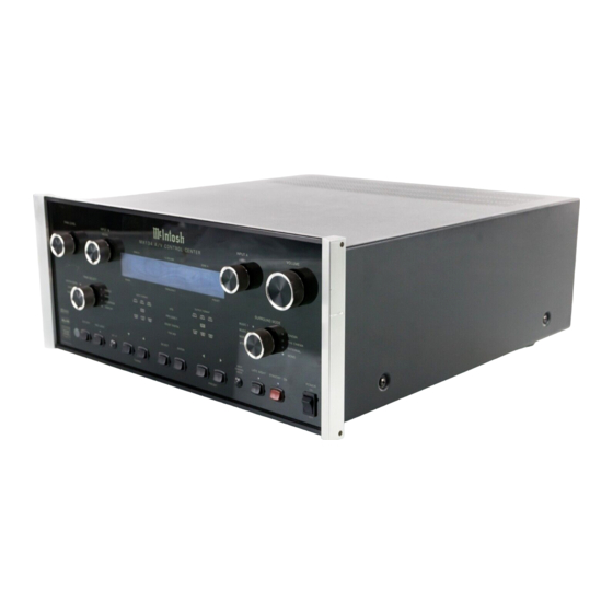
MX134 A/V Control Center
Manufactured under license from Dolby Laboratories, "Dolby", "Pro Logic II", "Pro Logic" and the
double D symbol are registered trademarks of Dolby Laboratories. Surround EX is a jointly developed
technology of THX and Dolby Labs, Inc., and is a trademark of Dolby. Used under authorization.
MX134
Lucasfilm, THX, THX ULTRA, the THX logo, Re Equalization, Re EQ, Timbre Matching,
Decorrelation, Bass Management, and Loudspeaker Position Time Synchronization are registered
trademarks of Lucasfilm, Ltd and manufactured under license from Lucasfilm Ltd. "DTS", "DTS ES",
"digital surround", and "coherent acoustics" are registered trademark of DTS Technology, LLC. and
are manufactured under license from DTS Technology LLC.
McIntosh Laboratory, Inc.
2 Chambers Street
Binghamton, New York 13903 2699
Phone: 607 723 3512
FAX: 607 724 0549
Advertisement
Chapters
Table of Contents

Related Manuals for McIntosh MX134


Summary of Contents for McIntosh MX134
- Page 1 Owner’s Manual MX134 A/V Control Center Manufactured under license from Dolby Laboratories, “Dolby”, “Pro Logic II”, “Pro Logic” and the double D symbol are registered trademarks of Dolby Laboratories. Surround EX is a jointly developed technology of THX and Dolby Labs, Inc., and is a trademark of Dolby. Used under authorization.
-
Page 2: Safety Instructions
The lightning flash with arrowhead, The exclamation point within an equi- within an equilateral triangle, is intended lateral triangle is intended to alert the to alert the user to the presence of user to the presence of important uninsulated “dangerous voltage” within operating and maintenance (servic- the product’s enclosure that may be of ing) instructions in the literature ac-... - Page 3 A. Use No. 10 AWG (5.3 mm ) copper No. 8 AWG McIntosh or have the same characteristics as the origi- (8.4 mm ) aluminum, No. 17 AWG (1.0 mm ) cop- nal part.
-
Page 4: Table Of Contents
Customer Service How to Adjust Zone B Setup ........... 37 If it is determined that your McIntosh product is in need of How to Change the Advanced Settings ......38 repair, you can return it to your Dealer. You can also return Operation it to the McIntosh Laboratory Service Department. -
Page 5: General Notes
Zones A and B. male to male cable. 16. When a McIntosh WK 2 Keypad or an R649 Sensor is to be 4. For additional connection information, refer to the owner’s connected to the McIntosh MX134 A/V Control Center that manual(s) for any component(s) connected to the MX134 A/V uses a RJ 45 Connector Plug instead of the “F”... -
Page 6: Connector Information
Connector Information Connector Information Keypad Terminal Connector Multizone Controller (DB37 Connector): To use a WK-3 or WK-4 Keypad with the MX134, connect 1. Accessory-On 14. LV-Left 26. CD-Data the shield and four leads of a shielded 4 conductor cable to 2. -
Page 7: Introduction
Now you can take advantage of traditional McIntosh stan- Digitally Controlled Volume and Tone Controls dards of excellence in the MX134 A/V Control Center as A Precision Tracking Volume Control adjusts all eight the heart of your Home Theater System. The MX134 pro- channels with tracking accuracy better than 0.5dB. -
Page 8: Dimensions
Dimensions Dimensions The following dimensions can assist in determining the best location for your MX134. There is additional informa- tion on the next page pertaining to installing the MX134 into cabinets. " 44.45cm Front View of the MX134 " "... -
Page 9: Installation
The four feet panel. Allow 1-1/8 inch (2.9cm) in front of the mounting may be removed from the bottom of the MX134 when it is panel for knob clearance. Be sure to cut out a ventilation custom installed as outlined below. -
Page 10: Rear Panel Multizone, Control And Switch
Rear Panel Multizone, Control Connections and Switch TO MULTIZONE SUM A Data Port for HOME Data Port CONTROLLER con- connections to the connects to the nects to the McIntosh other McIntosh Com- optional HC-1 Multizone Controller ponents Home Controller Input B... -
Page 11: Rear Panel Audio And Digital Connections
SAT, and LV receive a and 2 supply analog for connecting an external tuner digital audio signal from audio record signals to the MX134 when the optional the Optical Output of a for recorders TM1 Module is not installed in- component... -
Page 12: Rear Panel Video Connections
COMPONENT INPUTS receive OUTPUTS for VCR 1 and 2 Component Video (Y, P and P ) supply Composite Video Note: If the MX134 A/V System Control Signals from two Component Signals for recorders Center has the TM1 AM/FM Video Sources... -
Page 13: How To Connect Multizone And Control
How to Connect Multizone and Control How to Connect Multizone and Control 1. Connect a Data Control Cable from the MX134 DVD TROLLER Connector to the CR16 Multizone “Con- (input 11) Data Port to the McIntosh MVP841 DVD troller Input B” socket. -
Page 14: How To Connect Audio And Digital Components
B) OPTICAL DIGITAL INPUT to the Optical Digital Satellite Receiver Output of a Satellite Receiver. 5. Connect a cable from the MX134 Left and Right Ana- DVD Audio/SACD Player log Audio INPUTs (Input 6) to the Left and Right Analog Audio Out- puts of the Satellite Receiver. -
Page 15: How To Connect Video Components
Player. Video and Composite), using the appropriate Video Cables 6. Connect video cables from the MX134 COMPONENT to the MX134. This will assure that video is available to Video OUTPUTS to the Monitor/TV Component the Zone B and VCR Outputs. -
Page 16: How To Connect For Zone B
How to Connect for Zone B How to Connect for Zone B The MX134 is a Dual Zone A/V Control Center. For Zone 3. Connect a cable from the MX134 KEYPADS ZONE B B activation a McIntosh Sensor or Keypad together with a to the McIntosh Keypad. -
Page 17: Front Panel Controls And Sensor
Zone B Audio Outputs and Component and MONitor A Video MONitor B Video Outputs Outputs IR (Infra Red) Sensor accepts IR signals di- rectly from the MX134 Remote Control Selects the parameter Selects the desired audio for making audio and operating mode and selects... -
Page 18: Front Panel Push-Buttons And Switch
Front Panel Push-buttons and Switch Blocks input selection com- Allows for the storing Turns the MX134 On and mands coming from INPUT B into memory various Off , or resets all the (Zone B) to prevent interrupt- MX134 Settings MX134 microprocessors... -
Page 19: Front Panel Displays
Indicates when the Indicates when the and which channels are active; L (Left Front), Input Source selected MX134 is in C (Center), R (Right Front), LFE (Low Fre- is processing a Digital Standby/On Mode quency Effects), LS (Left Surround), S (Pro... -
Page 20: Remote Control Push-Buttons
Remote Control Push-Buttons Turns AC Power ON or OFF to certain McIntosh Components when connected via the Data Port Press to POWER the MX134 ON or OFF Selects Functions for McIn- tosh Home Controller Selects one of the twelve Audio/Video Sources... -
Page 21: How To Operate By Remote Control
Press the MUTE Push-button to mute audio in the Zone Acc On where the command is issued. The VCR OUTPUTS are not Press ACC ON to turn the power ON to a McIntosh Disc affected by the MUTE function. The MX134 Front Panel Player. -
Page 22: How To Operate The Setup Mode
Screen Menus. MAIN SYSTEM SETUP Notes: Menu will appear on the 1. To use the On Screen Menu feature, the MX134 MON A Monitor/TV Screen. Re- Video OUTPUT or COMPONENT Video OUTPUTS fer to figures 4, 5 & 6. must be connected to the video input of a Monitor/TV. -
Page 23: Default Settings
SETUP Default Settings The following listings indicate the factory default settings. Refer to the listed page number for instructions on how to change a default setting: MENU: MAIN SYSTEM SETUP Speaker Size: SPEAKER SIZE Speaker Type Speaker Setting Refer to Page SPEAKER TIME DELAY SPEAKER LEVEL Front ...... - Page 24 Analog Inputs (Zones A and B): Back Surround Modes (Zone A): Number Name Refer to Page Proccessing Mode Sound Field Mode Refer to Page 0 ......TUN (1*) ....30 THX Surround ..AUTO ......36 1 ......AUX (1*) ....30 DTS Matrix ...
-
Page 25: How To Adjust For Loudspeaker Size
YES to save those changes or NO not to quantity of Loudspeakers. If the setting for the Back save them. The MX134 will then return to normal op- Surround Loudspeaker is Small 1,only the Zone A eration. Refer to figure 7 on page 25. - Page 26 SUB Crossover: 80Hz{THX} made, select YES to save those changes or NO not to MC BASS MODE save them. The MX134 will then return to normal op- MAIN MENU eration. Refer to figure 7. Figure 8 ADJUSTMENTS HAVE BEEN MADE...
-
Page 27: How To Adjust Loudspeaker Time Delay
If you are satisfied with the changes that you may have made, select YES to save those changes or NO not to save them. The MX134 will then return to normal op- eration. Refer to figure 7 on page 26. -
Page 28: How To Adjust Loudspeaker Levels
A properly setup Home Theater Surround Sound System should have all Loudspeaker levels adjusted to the same starting reference volume level in the Listening/Viewing Area. The MX134 includes a built-in test signal generator, MENU: SPEAKER LEVEL AUTOMATIC {OFF} which can have its output switched into each Loudspeaker,... - Page 29 If you are satisfied with the changes that you may have Figure 13 made, select YES to save those changes or NO not to save them. The MX134 will then return to normal op- 13. Using the Up or Down directional push-buttons, eration.
-
Page 30: How To Change The Input Setup
How to Change the Input Setup The MX134 has eleven Analog Audio Inputs numbered 1 through 11, six Digital Audio Inputs lettered A through F and two Component Video Inputs numbered 1 and 2. These MENU: INPUT SETUP inputs already have assigned titles and associations that will allow for immediate hookup, operation and enjoyment. - Page 31 MAIN MENU MAIN MENU Figure 16 Figure 18 no components connected to them. If the MX134 is Digital Input connected to a McIntosh Multizone System Controller There are three Optical Digital Inputs and three Coaxial refer to note 13 on page 5 for additional information Digital Inputs available for assignment with any of the about reassigning Inputs.
- Page 32 Right directional push-buttons to select NONE. Note: The MX134 allows for assigning a Digital Input to multiple Analog Audio/Video Inputs. For example, the Digital Input F can be assigned to both the DVD1 and CD2 Inputs. When the MX134 Input Selector is set to...
- Page 33 Right directional Adjustments at this time, proceed to step 25 on page Video Converter The MX134 Video Converter feature allows the Up-Con- MENU: INPUT SETUP versions of Composite Video to S-Video and from S- SOURCE INPUT Video to Component Video. This will provide better pic-...
- Page 34 D-Coaxial may have made, select YES to save those changes or TAPE1 NO not to save them. The TAPE2 MX134 will then return to normal operation. Refer to B-Optical figure 7 on page 23. E-Coaxial C-Optical VCR1...
- Page 35 Notes...
-
Page 36: How To Change The Surround Mode Setup
If you are satisfied with the changes that you may have made, select YES to save those changes or NO not to save them. The MX134 will then return to normal op- eration. Refer to figure 7 on page 23. -
Page 37: How To Adjust Zone B Setup
If you are satisfied with the changes that you may have made, select YES to save those changes or NO not to save them. The MX134 will then return to normal op- eration. Refer to figure 7 on page 23. -
Page 38: How To Change The Advanced Settings
If you are satisfied with the changes that you may have MENU: DIGITAL SETTINGS made, select YES to save those changes or NO not to DIGITAL LOCK: save them. The MX134 will then return to normal op- RC INPUT TOGGLE: eration. Refer to figure 7 on page 23. ADVANCED MENU... - Page 39 Menu, followed by pressing the SELECT Push-but- Version Check ton. McIntosh makes different versions of the MX134 to meet the requirements in each country it is sold. The MX134 can display that version information by the following steps. Re- fer to figure 30. MENU: RESTORE DEFAULTS 14.
- Page 40 Menu. If you are satisfied with the changes that you may have made, select YES to save those changes or NO not to save them. The MX134 will then return to normal operation. Refer to figure 7 on page 23.
-
Page 41: How To Operate The Mx134
Controller is not going to be used for an extended nels simultaneously, and level period of time, turn Off all AC Power with the Power Figure 36 is indicated from 0 to 99 in the Switch. If the MX134 is in the Stand by Mode and is Figure 35... - Page 42 Menu Surround Mode Setting. Refer to figures 37, 38 and System. Note: The Surround Mode THX and/or DTS Menu Settings in Tuning the MX134 SETUP need to be set to either On or Auto The TUNING Up and Down Push-buttons allow for...
- Page 43 Reset of Microprocessors H. The THX REF (Reference) Display will illuminate In the event that the controls of the MX134 stop function- when the Volume control is set to the THX level. The ing, there is a user reset function built in. Press the THX default volume level is 65%, but it will change POWER Switch to OFF and wait for two minutes.
-
Page 44: How To Operate The Trim Mode
How to Operate the Trim Mode 2. Low The MX134 TRIM SELECT Switch together with the Frequency TRIM LEVEL Control provide the means for adjusting Information seven different audio functions and the Front Panel Alpha- must be present numeric Display Brightness. This can be accomplished... - Page 45 Surround Mode is set to the THX CINEMA, a flat tonal TRIM SELECT Control, until DISPLAY appears on response will be reset for that input when the MX134 is the Front Panel Alphanumeric Display. A number to the switched Off.
-
Page 46: How To Operate The Surround Mode
How to Operate the Surround Mode The MX134 provides eight different Surround Modes. The Front Panel Alphanumeric Display and the Output Format LEDs will indicate the Surround Mode selected. The Sur- round Mode Selected is stored into permanent memory and... - Page 47 THX CINEMA. The Output Format LEDs L, C, R, LS, RS and SUB will illuminate. Refer to figures 65 and 66. Note: If the Back Channel Surround Mode is set to On or Auto in the MX134 Surround Mode Setup the BS Output Format LED may also illuminate.
-
Page 48: How To Make A Tape Recording
How to Operate Zone B The separate INPUT B (Record) and INPUT A (Listen) The MX134 includes the feature of being able to operate Switches allow for the making of a recording from one pro- and control two Audio/Video Zones, independent of each gram source while listening to another. - Page 49 How to Operate the MX134, con’t Figure 74 2. Select the desired Zone B Source and adjust the Vol- ume to the desired listening level by pressing the ap- propriate push-buttons on the Keypad or Remote Con- trol. Refer to figure 74 and 75.
-
Page 50: Audio And General Specifications
220 Volts, 50/60Hz at 65 watts 20Hz-20,000Hz 230 Volts, 50/60Hz at 65 watts Subwoofer: 240 Volts, 50/60Hz at 65 watts 20Hz-80Hz Note: Refer to the rear panel of the MX134 for the correct voltage. EXTERNAL Left, Center, Right, Left Surround, Overall Dimensions INPUT Right Surround: Front Panel: 17-1/2 inches (44.5cm) wide, 7-5/8 inches... - Page 51 Notes...
-
Page 52: Tm1 Am/Fm Tuner Module
TM1 AM/FM Tuner Module Introduction Cables for installing the McIntosh TM1 Cable for connecting the The MX134 A/V Control Center has provisions for adding AM/FM Tuner Module RAA1 to the MX134 an optional McIntosh TM1 AM/FM Tuner Module for Ra- into the MX134 dio Station Reception. -
Page 53: Antenna Connections
MX134 Rear Panel and RAA1 Top Panel Antenna Connections RAA1 Remote Antenna can be adjusted to a position for optimum reception of your fa- vorite AM stations Connects with supplied cable to the MX134 AM ANT (An- tenna) connector allows a McIntosh... -
Page 54: How To Connect Antenna Components
Note: If a longer length cable needs to be used between the connection information on the top MX134 and the RAA1, use a 2 conductor shielded cable. cover of the RAA1. 2. Connect a 75 ohm coax cable from an FM Antenna or cable system to the MX134, 75 OHM FM ANTenna Connector. -
Page 55: How To Operate The Tuner
How to Operate the Tuner How to Tune Stations Manually The McIntosh MX134 TM1 AM/FM Tuner Module incor- move continuously up or porates an advanced design AM/FM Tuner with many de- down the broadcast band. sirable performance features to enhance your enjoyment of When a station is selected, radio broadcasts. -
Page 56: How To Assign Preset Stations
How to Assign Preset Stations How to Assign Preset Stations The MX134 AM/FM Tuner Module (TM1) allows for pre- Display will indicate the number of the next available setting radio stations into memory. To enter Presets follow Preset. the below steps:... -
Page 57: How To Optimize Am Reception
How to Optimize AM Reception How to Optimize AM Reception The McIntosh RAA1 Remote AM Antenna is designed to METALLIC tool, adjust the 600kHz Transformer L1 provide the best in AM Reception especially if the tuner or for maximum signal strength. Refer to figure 84. -
Page 58: Fm Specifications
TM1 FM and AM Specifications FM Tuner Specifications AM Tuner Specifications Useable Sensitivity Sensitivity 14dBf which is 1.4uV across 75 ohms 20uV External Antenna Input 50dB Quieting Sensitivity Signal To Noise Ratio Mono: 19dBf which is 2.4uV across 75 ohms 48dB at 30% modulation Stereo: 35dBf which is 15uV across 75 ohms 58dB at 100% modulation... -
Page 59: Packing Instructions
If a shipping 034037 Inner carton pad carton or any of the interior part(s) are needed, please call or write Customer Service Department of McIntosh Labo- 017218 Plastic foot ratory. Please see the Part List for the correct part numbers. - Page 60 McIntosh Laboratory, Inc. 2 Chambers Street Binghamton, NY 13903 McIntosh Part No. 040754...