Table of Contents

Related Manuals for Neilsen BDE3500E

Summary of Contents for Neilsen BDE3500E
- Page 1 ORIGINAL INSTRUCTIONS PLEASE READ THIS MANUAL CAREFULLY. IT CONTAINS IMPORTANT SAFETY INFORMATION. DIESEL GENERATOR SINGLE PHASE: BDE2200E BDE3500E BDE5000E BDE6500TW BDE6700T BDE6500T BDE6700TN BDE6500TW3 BDE6700T3 BDE6500T3 BDE6700TN3...
- Page 2 EC Directive based on its design and type, as brought into circulation by In case of alteration of the machine, not agreed upon by us, this declaration will lose its validity. Product description: Diesel Generator Model: CT2020 BDE2200E CT1848 BDE3500E BDE5000E CT1788 BDE6500TW CT0405 BDE6700T BDE6500T...
- Page 3 Symbols used in this manual General safety warnings The generator may only be used in well ventilated areas. The rated power of a connected power consuming load must not exceed the generator’s rating. Overloading the generator poses a risk and can lead to serious damage and/or injury. Disconnect the generator before carrying out any kind of maintenance.
- Page 4 Never allow children or animals near the generator at least 5m. Do not allow the generator to run out of fuel when a load is connected. During operation voltage fluctuations may occur. Sensitive electronic devices like television sets or computers may only be operated in conjunction with a surge protector. Do not interfere with the internal wiring.
- Page 5 Remove the spark plug maintenance cover and remove the spark plug cap. Turn the engine switch to the OFF position. Pull the starter cord 3 or 4 times to empty the fuel pump of diesel, into a suitable container. Turn the engine switch to the OFF position and tighten the carburetor drain screw. Work area safety Among engine exhaust emissions, there is Toxic CO, so never use in an enclosed room without good ventilation.
- Page 6 Dry chemical fire extinguisher to be used. Electric hazard Do not operate the generator near water, in damp or wet conditions. Do not touch the generator with wet hands. Do not clean the generator with water. The generator must not be connected to a mains supply or any other electrical source. If an extension cable is required, ensure that the conductors are of sufficient diameter to carry the current drawn by any power consuming device connected.
- Page 7 Maintenance Good maintenance is essential for safe, economical, and trouble-free operation, It will also help reduce air pollution. Exhaust gas contains poisonous carbon monoxide. Shut off the engine before performing any maintenance. If the engine must be run, make sure the area is well ventilated. Periodic maintenance and adjustment is necessary to keep the generator in good operating condition.
- Page 8 1. MAIN TECHNICAL SPECIFICATIONS AND DATA 1.1 Main Technical Specifications and Data Generating set...
- Page 9 Engine Sound pressure level LpA: 75.1 dB(A) Sound power level LwA: 95.1 dB(A) Guaranteed sound power level LwA: 97 dB(A) Note: A is intelligent control panel...
- Page 10 Proper use The device is designed for applications operated with 230 V and 115V alternating current source. Be sure to observe the restrictions in the safety instructions. The generator is intended to provide electric tools and light sources with electricity. When using the device with household appliances, please check their suitability in accordance with the relevant manufacturer’s instructions.
- Page 11 Operation Important! You must fill up with engine oil (approx. 0.6 l) and fuel before you can start the engine. Check the fuel level and top it up if necessary Make sure that the generator has sufficient ventilation Make sure that the ignition cable is secured to the spark plug Inspect the immediate vicinity of the generator Disconnect any electrical equipment which may already be connected to the generator 1.
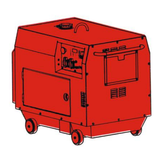
- Page 12 2.1 Parts name(BDE series E/X type)
- Page 13 2.1 Parts name(BDE series T type)
- Page 14 2.2 Control panel C type panel E type panel E model receptacle panel E3 type three-phase panel EW welding panel E type basic model panel E type panel A model double voltage panel Intelligent control panel...
-
Page 15: Preparation For Starting
3. PREPARATION FOR STARTING 3.1 Selection and handling of the fuel oil Selection of fuel oil Only use the light diesel, which is most suitable for the engine. Keep dust and water out of the fuel When filling the fuel tank from drums, make sure that no dust or water is mixed in the fuel. Otherwise the serious fuel injection pump and nozzle problems will result. - Page 16 CAUTION: OUR series generating set are equipped with low oil warning system. This system will stops the engine automatically when the oil level falls below the lower level. This prevents accidents such as bearing seizures, etc. Select the most applicable engine oil It is very important to select the applicable engine oil for keep up the performance and life of the generating set.
- Page 17 Reattach the air cleaner cover and screw on the wing nut. Element 3.4 Check the generating set Turn off the main switch and any other Loads. WARNING: Be sure to turn off the main switch before starting. The generating set should be earthed to prevent electric shocks.
- Page 18 Handling of dual voltage type generating sets. Be sure to place the changeover switch in the correct position for the rated voltage of the working instrument. CAUTION The main switch should always be kept in the “ON” position during operation. ...
-
Page 19: Start The Generating Set
Avoid applying any heavy loads during the break-in period. Recommends to run the engine at 3000r/min with 50% load in break-in period. Replace the engine oil on time. Replace the engine oil while the engine is warm after 20-hours-running, the old engine oil will be drained out completely. - Page 20 Set the engine speed lever at the position. Engine speed lever Photo shows RUN position Pull out the recoil starter handle. Pull out the handle until you feel the resistance, then return it back to the initial position. Press down the decompression lever.
- Page 23 4.2 Electric starting 1. Starting (The preparations for electric starting are the same as for the recoil Starting.) Open the fuel cock. Set the engine speed lever at “RUN” position. Engine speed lever Photo shows RUN position Engine starter key ...
-
Page 24: Operate The Generating Set
2. Battery Check the battery electrolyte level every month. Refill the distilled water until the upper limits if the electrolyte dropped to the lower limits. CAUTION If the electrolyte level is too low, the engine may fail to start because there is not sufficient power.On the other side if the electrolyte level is too high,the fluid will corrode the surrounding parts. - Page 25 CAUTION For the generating set with Low Oil Warning System, the Oil Alarm Lamp will activated by low oil pressure or engine oil shortage, simultaneously, the engine will stop. The engine will stop immediately if restarted without refilling the engine oil. Check the oil level and refill. ...
- Page 26 6.1 AC application 1. Be sure to run the generating set at rated speed, otherwise AVR(Automatic Voltage Regulator) will produce the forced excitation. If the running is for a long time unser such condition,AVR will be burned out. 2. After switching on the air switch, observe the voltmeter on the panel of the control cabinet, the voltmeter should point to 230V±5%(50Hz) for single-phase generating set;400V±...
- Page 27 6.2 DC application 1. DC terminals are only for charging 12V battery. 2. Set the air switch at “OFF” position while charging. On the 12V output terminals, a charge switch can be connected so the switch can be used for on-and-off purpose. 3.
- Page 28 6.3 Electrical appliance particularly motor-driven equipment will produce very high current while starting, the below table provides the reference for connecting these apparatus to the generating set. WATTAGE EXAMPLE TYPICAL TYPE STARTING RATED APPLIANCE APPLIANCE STARTING RATED ●Incandescent lamp Incandescent 100VA(W 100VA(W) ●Heating...
- Page 29 7. STOP YOUR GENERATING SET 1. Disconnect the load from the generating set. 2. Turn off the air switch of the generating set. 3. Set the speed lever at “RUN” POSITION, run the generating set without load for about 3 minutes.
- Page 30 8. PERIODIC CHECK AND SERVICE Periodic check and service are very important for keeping the engine in good condition and durable. The chart below indicates what checks to make and when to make them. WARNING Shut off the engine before performing any service. If the engine must be run, make sure the area is well ventilated.
- Page 31 8.1 Replace engine oil Remove the oil filler cap. Remove the drain plug and drain the old oil while the engine is still warm. The plug is located on the bottom of the cylinder block. Tighten the drain plug and refill with the Oil filler cap/Dip stick recommended oil.
- Page 32 1. Drain out the fuel from the fuel tank. Fuel tank Loosen the three small screws and remove the fuel filter 2. Drain out the fuel from the fuel tank. Screw off the small screw of the fuel cock and pull out the filter from the filer port. 3.
- Page 33 8.7 Check and refill the battery electrolyte and charge the battery The diesel uses a 12V battery. Battery electrolyte will be lost through continuous charging and discharging. Before starting, check for physical damage to the battery and also the electrolyte levels, and refill the distilled water till to the upper level if necessary.
- Page 34 9. LONG-TERM STORAGE If store the generating set for long periods, make the following preparation. Operate the engine for about 3 minutes and then stop. Stop the engine. Drain the engine oil while the engine is still warm and fill with fresh oil.
-
Page 35: Troubleshooting And Remedy
10. TROUBLESHOOTING AND REMEDY Fault Cause Remedy Fuel oil is not sufficient. Refill the fuel oil. Fuel cock is not at START Turn it to START position. position. Fuel injection pump and nozzle Remove the nozzle and repair it at do not delivery the fuel or delivery test table. - Page 36 Electric Wiring Diagram for All Types of the Set <1> C type electric wiring diagram...
- Page 37 <2> X type electric wiring diagram (single voltage output)
- Page 38 <3> X type electric wiring diagram (double voltage output)
- Page 39 <4> E type electric wiring diagram (single voltage output)
- Page 40 <5> E type electric wiring diagram (double voltage output)
- Page 41 <6> T type electric wiring diagram...
- Page 42 <7> X3, E3 type electric principle diagram Description:For set X3 type, the components in the two-point-and-line box are not mounted.
- Page 43 <8> X3, E3 type electric principle diagram...
- Page 44 CANNON TOOLS LTD 20 Station Road, Rowley Regis, West Midlands, B65 0JU.U.K Made in China...