Table of Contents
Advertisement
Quick Links
Wireless Multimedia Link
TABLE OF CONTENTS
Technical specification ......................................................1-1
Connections & Controls.....................................................1-2
Accessories .......................................................................1-3
Safety & Warnings.............................................................1-4
ESD protection equipment.................................................1-4
Handling chip components............................................2-1
Tips for troubleshooting.................................................2-2
Service Test Program ........................................................3-1
Block diagram ....................................................................3-2
©
Copyright 2004 Philips Consumer Electronics B.V. Eindhoven, The Netherlands
All rights reserved. No part of this publication may be reproduced, stored in a retrieval
system or transmitted, in any form or by any means, electronic, mechanical, photocopying,
or otherwise without the prior permission of Philips.
Published by PW 0418 Service Audio
Version 1.0
Printed in The Netherlands
Subject to modification
StreamIOm Module G1.0/LinX ......................................4-1
Main Board ..................................................................4-14
Printed circuit boards
StreamIOm Module G1.0/LinX ....................................4-10
Main Board ..................................................................4-19
Exploded view ...................................................................5-1
Partslist..............................................................................6-1
Revision list .......................................................................6-1
SL300i
all versions
© 3103 785 25250
Advertisement
Table of Contents

Related Manuals for Philips SL300I/00


Summary of Contents for Philips SL300I/00
-
Page 1: Table Of Contents
Block diagram ..............3-2 © Copyright 2004 Philips Consumer Electronics B.V. Eindhoven, The Netherlands All rights reserved. No part of this publication may be reproduced, stored in a retrieval system or transmitted, in any form or by any means, electronic, mechanical, photocopying, or otherwise without the prior permission of Philips. -
Page 2: Technical Specification
TECHNICAL SPECIFICATION General Dimensions (incl. sockets & feet) : 184 x 196 x 65mm Net weight : 0.8kg Power supply (via external AC/DC-Adaptor) Mains voltage (AC) : 98-264V, 50-60Hz Power consumption : 17W max., <1W standby Video playback performance S/N Luminance : >60dB S/N Chrominance AM : >60dB... -
Page 3: Connections & Controls
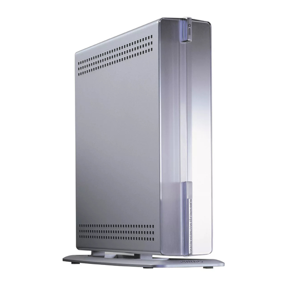
CONNECTIONS & CONTROLS Front View (all versions) Rear View (version /37) Rear View (versions /00/05/19) s ' i ACCESSORIES & e i l... -
Page 4: Safety & Warnings
SAFETY & WARNINGS SAFETY Safety regulations require that the set be restored to its Veiligheidsbepalingen vereisen, dat het apparaat in zijn original condition and that parts which are identical with oorspronkeliijke toestand wordt teruggebracht en dat those specified be used. onderdelen, identiek aan de gespecificeerde, worden toegepast. -
Page 5: Service Hints
SERVICE HINTS HANDLING CHIP COMPONENTS... -
Page 6: Tips For Troubleshooting
TIPS FOR TROUBLESHOOTING 1. General information The Wireless Multimedia Receiver SL300i contains the following printed boards and modules: • External AC/DC-Adaptor • Main Board • Internet A/V-Module “StreamIOm G1.0/LinX” • WiFi-Antenna (2x) • Stand Illumination Board The external AC/DC-Adaptor, the Main Board and the Internet A/V module are not intended to be repaired on component level. When shallow faultfinding fails and diagnostics threaten to escalate, the board/module in question should be replaced entirely. - Page 7 4. Wiring instructions for WiFi-Antennas Caution: The terminals for the WiFi-Antennas must not be interchanged! The cable connected to the “Main” terminal on the WiFi-Card MUST be connected to the antenna on the right side of the set (seen from front panel). Wrong wiring will disturb the functionality of the IR-Receiver and cause serious problems with the Remote Control in WiFi mode.
-
Page 8: Service Test Program
Menu/AS Language Others 4..6 Architecture Feature Set 001, 002, Refer Version Matrix iSIO Test 5 003, etc. RGB/YUV test 7..8 OEM Derivative Philips (see table 2) Grundig Marantz B&O Magnavox Loewe Yamaha RC “STOP” Hitachi pressed? Audio etc. -
Page 9: Block Diagram
BLOCK DIAGRAM WiFi ANT. 1 WiFi ANT. 2 iSIO G1.0/LinX MAIN BOARD SCART +3.3V +3.3V RJ45 CONNECTOR 7120 7124 +2.5V MAST. CVBSOUT WiFi CARD RESET +3.3V 30MHz CLOCK +3.3V 12V_SW FBOUT MINI PCI CONNECTOR ROUT 5300 7403 7126 7706 RED/CR/C/CVBS ROUT/C 10/100BASE-TX GOUT... -
Page 10: Circuit Diagrams
Internet A/V Module – Service Hints The Internet A/V Module StreamIOm G1.0/LinX is not intended to be repaired on component level. Only the complete Printed Board Assembly and the Wireless LAN Card are available as service spare part. These articles can be ordered with the following codenumbers: StreamIOm G1.0/LinX PBAS ..3103 308 67790 Wireless LAN Card.......9307 008 01371... - Page 11 0002 A1 2105 B4 2114 H6 2121 H4 2127 H4 2134 D3 3116-2 G10 3124 B6 3138 B7 3145 E7 3148-1 F7 3153-1 G9 3157-3 G9 3180 B7 3186 F14 3192 G9 4101 E12 4107 F14 4113 A12 5100 D2 7121 B5 F101 A5 F113 E9...
- Page 12 2201 B10 2250 H11 2256 H13 2262 A7 2271 I13 2277 I15 2283 I10 3205 B8 3211 C8 3217 C8 3223 C8 3229 C8 3236 C8 3242 D4 3248 D4 3254 D4 3260 D4 3266 E4 3272 G4 3278 G4 3284 G4 3290 G4 3296 G4...
- Page 13 1300 D1 2302 E3 2310 B4 2314 G8 2325 A3 2329 B2 2333 C4 2339 H3 3336-A A7 3338 A9 3344 D3 3352 E4 3356 F10 3360 A12 4306 A13 4320 A12 5302 B4 5306 B2 6300 F10 F316 D10 T300 D1 T319 F2 c1004 G3...
- Page 14 1400 H13 T414 I12 1401 A1 T415 I12 1402 E1 T416 I12 1403 H9 T417 H13 2404 B2 T418 H11 GP - IO INTERFACE 2405 B3 T419 H12 2406 B2 T420 B2 2407 B3 T450 A2 +3.3V 2408 B3 T451 B2 2409 C10 T452 B2 2410 C10...
- Page 15 2501 D2 2512 C6 2518 F8 2523 F4 2528 G9 2534 H8 2541 G4 3514 C9 3520 F6 3528 G6 3538 H7 3545 C7 3550 C9 3555 H4 3560 F7 4509 D11 4514 D6 4519 E9 5504 E9 7509-B E11 F501 B9 F514 G9 F519 G12...
- Page 16 1601 A14 2603 A12 2610 D10 2615 D5 2623 E12 2628 G8 2635 H11 2641 H7 3604 B10 3609 C11 3614 D10 3620 E11 3625 E11 3630 F11 3635 F11 3641 G4 3646 G4 3651 H10 4602 H6 4613 A13 5601 D7 7600-B B11 7609-B H11...
- Page 17 1700 D14 4709 F10 2700 B3 4710 F10 2702 B3 4711 E12 2703 B4 4712 E12 2704 B2 4713 E12 VIDEO ENCODER 2705 B6 4714 E12 2707 B4 4717 F5 2708 B6 4719 B5 2709 B5 4720 D12 2710 D8 4721 C3 2711 D10 4724 B4...
- Page 18 1800 B1 7810 E3 1801 D1 7811 G3 1802 B5 7812 I2 1803 B3 7813 E2 1804 B8 7814 E2 POWER SUPPLY 1805 D1 7815-1 I3 1806 G2 7816 H3 1807 G10 7817 H13 2806 B5 7818 H6 2807 B8 T800 E8 2808 B9 T801 B1...
- Page 19 4-10 4-10 PRINTED BOARD ASSEMBLY – StreamIOm G1.0/LinX – Side A...
- Page 20 4-11 4-11...
- Page 21 4-12 4-12...
- Page 22 4-13 4-13 PRINTED BOARD ASSEMBLY – StreamIOm G1.0/LinX – Side B...
-
Page 23: Main Board
4-14 4-14 STAND ILLUMINATION Stand Illumination Board WH03D-1 1501 Main Board This board is not intended to be repaired on component level. Circuit Diagrams and Printed Circuit Board drawings are published for orientation only. In case of defects please replace the entire board. Boards can be ordered with the following codenumbers: Main Board EUR Version /00/05/19 3103 308 67800... - Page 24 4-15 4-15 1101 A9 6101 B6 1102 D13 6102 B6 1103 G13 6103 B7 1104 F13 6104 B7 VIDEO OUT 1105 I1 6105 B8 1106 G13 6106 B8 EUR version only 2101 A2 6107 F11 2102 C4 6108 E12 -5VESD 3101 F113 F114...
- Page 25 4-16 4-16 1201-1 E7 1202 B8 2201 E7 2202 E6 2203 E6 SL-300i FRONT AREA 2204 F7 2210 C1 2211 C2 2212 D2 2213 B5 2214 E3 2215 D4 provisional 2216 D4 2217 C8 2218 D8 2219 F7 1202 3201 C8 F210 3202 C8 74LVC14AD...
- Page 26 4-17 4-17 1301 A1 2303 A4 2307 D4 2311 E4 2315 D10 3302 A2 3306 A3 3310 B5 3314 D5 3318 E5 3322 E6 3328 E7 3332 E7 3336 C8 3340 C8 3344 E9 3348 E6 3352 C9 5302 B8 5307 D9 F301 A1 F305 B1...
- Page 27 4-18 4-18 1401 A1 2402 E3 2406 E4 2410 E6 2414 A8 2418 A4 3404 A2 3408 B3 3412 A4 3416 B7 3420 B7 3424 B8 3428 C8 5404 E6 7401 D2 7405 B3 F410 A8 F414 A2 F418 D8 F422 D9 1402 A9 2403 E1...
- Page 28 4-19 4-19...
- Page 29 4-20 4-20...
-
Page 30: Exploded View
EXPLODED VIEW FAN-Mounting direction Cable-location 1001 WiFi-Antenna 1002 Main Board WiFi-Card StreamIOm G1.0/LinX 1011 WiFi-Antenna... -
Page 31: Partslist
PARTSLIST REVISION LIST 101 3103 607 50801 Cabinet Right Service Manual 3103 785 25250 – Version 1.0 102 3103 607 50831 Window Front • Initial release 107 3103 607 50822 Cabinet Left 114 3103 607 50901 Stand 210 3103 301 72061 Rubber 225 3139 118 79761 Fan KD1245PFS3...