Sony CDX-GT828U Service Manual
Fm/mw/lw compact disc player
Hide thumbs
Also See for CDX-GT828U:
- Operating instructions manual (140 pages) ,
- Installation/connections (2 pages)
Table of Contents
Advertisement
SERVICE MANUAL
Ver. 1.0 2007.12
• The tuner and CD sections have no adjustments.
CD Player section
Signal-to-noise ratio: 120 dB
Frequency response: 10 – 20,000 Hz
Wow and fl utter: Below measurable limit
Tuner section
FM
Tuning range:
CDX-GT828U:
87.5 – 108.0 MHz
CDX-GT870US/GT878US:
87.5 – 108.0 MHz (at 50 kHz step)
87.5 – 107.9 MHz (at 200 kHz step)
FM tuning interval:
CDX-GT870US/GT878US:
50 kHz/200 kHz switchable
Antenna (aerial) terminal:
External antenna (aerial) connector
Intermediate frequency: 10.7 MHz/450 kHz
Usable sensitivity: 9 dBf
Selectivity: 75 dB at 400 kHz
Signal-to-noise ratio:
67 dB (stereo), 69 dB (mono)
Harmonic distortion at 1 kHz:
0.5 % (stereo), 0.3 % (mono)
Separation: 35 dB at 1 kHz
Frequency response: 30 – 15,000 Hz
Sony Corporation
9-887-933-01
2007L04-1
Audio Business Group
©
2007.12
Published by Sony Techno Create Corporation
CDX-GT828U/GT870US/
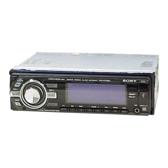
Photo: CDX-GT828U
Model Name Using Similar Mechanism
CD Drive Mechanism Type
Optical Pick-up Name
SPECIFICATIONS
MW/LW
CDX-GT828U:
Tuning range:
MW: 531 – 1,602 kHz
LW: 153 – 279 kHz
Antenna (aerial) terminal:
External antenna (aerial) connector
Intermediate frequency:
10.7 MHz/450 kHz
Sensitivity:
MW: 30 μV, LW: 40 μV
FM/MW/LW COMPACT DISC PLAYER
FM/AM COMPACT DISC PLAYER
GT878US
AEP Model
UK Model
CDX-GT828U
E Model
CDX-GT870US/GT878US
CDX-GT620U/670U/
GT670US
MG-101I-188//Q
DAX-25A
AM
CDX-GT870US/GT878US:
Tuning range:
531 – 1,602 kHz (at 9 kHz step)
530 – 1,710 kHz (at 10 kHz step)
AM tuning interval:
9 kHz/10 kHz switchable
Antenna (aerial) terminal:
External antenna (aerial) connector
Intermediate frequency: 10.7 MHz/450 kHz
Sensitivity: 30 μV
– Continued on next page –
CDX-GT828U
CDX-GT870US/GT878US
Advertisement
Table of Contents

Related Manuals for Sony CDX-GT828U


Summary of Contents for Sony CDX-GT828U
- Page 1 0.5 % (stereo), 0.3 % (mono) Separation: 35 dB at 1 kHz FM/MW/LW COMPACT DISC PLAYER Frequency response: 30 – 15,000 Hz CDX-GT828U FM/AM COMPACT DISC PLAYER CDX-GT870US/GT878US Sony Corporation 9-887-933-01 2007L04-1 Audio Business Group © 2007.12 Published by Sony Techno Create Corporation...
- Page 2 COMPONENTS IDENTIFIED BY MARK 0 OR DOTTED LINE WITH MARK 0 ON THE SCHEMATIC DIAGRAMS AND IN THE PARTS LIST ARE CRITICAL TO SAFE OPERATION. REPLACE THESE COMPONENTS WITH SONY PARTS WHOSE PART NUMBERS APPEAR AS SHOWN IN THIS MANUAL OR IN SUPPLEMENTS PUBLISHED BY SONY.
-
Page 3: Table Of Contents
CDX-GT828U/GT870US/GT878US This compact disc player is classifi ed as a CLASS 1 LASER TABLE OF CONTENTS product. The CLASS 1 LASER PRODUCT label is located on the exterior. SERVICE NOTE ............. GENERAL Location of Controls ............Connections ..............This label is located on the bottom of the chassis. -
Page 4: Service Note
CDX-GT828U/GT870US/GT878US SECTION 1 SERVICE NOTE EXTENSION CABLE AND SERVICE POSITION NOTE FOR REPLACEMENT OF THE SERVO BOARD When repairing or servicing this set, connect the jig (extension When repairing, the complete SERVO board (A-1362-921-A) cable) as shown below. should be replaced since any parts in the SERVO board cannot be repaired. -
Page 5: General
CDX-GT828U/GT870US/GT878US SECTION 2 GENERAL This section is extracted from instruction manual. • Location of Controls • CDX-GT828U: Location of controls and basic operations Main unit SOURCE button RESET button page 5 To power on; change the source (Radio/CD/ (eject) button page 7 USB/AUX)*. -
Page 6: Connections
CDX-GT828U/GT870US/GT878US • Connections • CDX-GT828U: Note for the antenna (aerial) connecting Hinweis zum Anschließen der Antenne Remarque sur le raccordement de Nota per il collegamento dell’antenna Opmerking bij de antenne-aansluiting If your car antenna (aerial) is an Wenn Ihre Fahrzeugantenne der l’antenne... -
Page 7: Connection Diagram
CDX-GT828U/GT870US/GT878US • CDX-GT870US/GT878US: RCA pin cord (not supplied) Insert with the cord upwards. Supplied with the CD/MD changer Cable con terminales RCA (no suministrado) Insertar con el cable hacia arriba. Suministrado con el cambiador de CD/MD BUS AUDIO IN FRONT... -
Page 8: Disassembly
CDX-GT828U/GT870US/GT878US SECTION 3 DISASSEMBLY • This set can be disassembled in the order shown below. 3-1. SUB PANEL ASSY (Page 9) 3-2. CD MECHANISM BLOCK (Page 9) 3-4. SERVO BOARD 3-3. MAIN BOARD (Page 10) (Page 10) 3-5. CHASSIS (T) SUB ASSY (Page 11) 3-6. -
Page 9: Sub Panel Assy
CDX-GT828U/GT870US/GT878US Note: Follow the disassembly procedure in the numerical order shown below. 3-1. SUB PANEL ASSY two claws CN702 (3P) two claws flexible flat cable (23 core) two screws (CN370) (+PTT 2.6 × 6) sub panel assy 3-2. CD MECHANISM BLOCK... -
Page 10: Main Board
CDX-GT828U/GT870US/GT878US 3-3. MAIN BOARD screw two screws screw (+PTT 2.6 × 10) (+P 2.6 × 8) (+PTT 2.6 × 8) two screws (+PTT 2.6 × 10) two screws (+P 2.6 × 10) connection three ground point screws cord (RCA) (+PTT 2.6 × 6) two screws (+PTT 2.6 ×... -
Page 11: Chassis (T) Sub Assy
CDX-GT828U/GT870US/GT878US 3-5. CHASSIS (T) SUB ASSY two precision screws two precision screws (+P 1.7 × 2.2) (+P 1.7 × 2.2) chassis (T) sub assy claw 3-6. ROLLER ARM ASSY roller arm assy gear (RA1) spring (RAL) washer spring (RAR) -
Page 12: Chassis (Op) Assy
CDX-GT828U/GT870US/GT878US 3-7. CHASSIS (OP) ASSY chassis (OP) assy tension spring (KF) coil spring (damper) (natural) coil spring (damper) (green) slider (R) lever (D) gear (LE1) 3-8. CHUCKING ARM SUB ASSY chucking arm sub assy spring Note: Have this portion receive the chassis. -
Page 13: Sled Motor Assy
CDX-GT828U/GT870US/GT878US 3-9. SLED MOTOR ASSY three serration screws (M 2 × 3) sled mtor assy spring turn table spring stand Note: Never remove these parts since they were adjusted. stand Note: Place the stand with care not to touch the turn table. -
Page 14: Optical Pick-Up Section
CDX-GT828U/GT870US/GT878US 3-10. OPTICAL PICK-UP SECTION optical pick-up section Note: Be careful not to touch the lens and hologram terminal when removing the optical pick-up section. 3-11. OPTICAL PICK-UP pan tapping screw (M 1.4 × 2.5) leaf spring (sub guide) leaf spring (OP) -
Page 15: Diagnosis Function
CDX-GT828U/GT870US/GT878US SECTION 4 DIAGNOSIS FUNCTION Description of the Diagnostics function: 4. Contents of each display mode 4-1. Reset count display mode 1. Setting the Diag display mode With the power off, press the [4/ALBUM +] button, [5/DM+] button, and [4/ALBUM +] button on the set body or the remote control (for more than 2 seconds) in turn. - Page 16 CDX-GT828U/GT870US/GT878US 4-6. OFFSET/FAILURE error display mode 4-5. CD error information display mode 4-5-1. Error description XXXXX Operating hours Error information Error description Error description Indication Description (0: OFFSET, 1: FAILURE) (in hexadecimal format) SERVO ERROR Recency of information LOADING ERROR 1-3: 1 represents the latest.
- Page 17 CDX-GT828U/GT870US/GT878US 4-7-2. Disc type and operating hours The display mode is switched by each rotation of [4/ALBUM +] or [3/ALBUM –] keys during the CD error information display mode. XXXX Operating hours USB error info history 1 (latest) Error description plus error details display Recency of information 1-5: 1 represents the latest.
-
Page 18: Diagrams
CDX-GT828U/GT870US/GT878US SECTION 5 DIAGRAMS • Semiconductor Location (KEY Board) Ref. No. Location Ref. No. Location (D902) F-11 LED906 C-2 (D905) I-12 LED907 D-2 (D906) H-10 LED908 C-5 (D907) H-10 LED909 D-7 (D908) I-11 LED910 D-6 (D909) H-10 LED911 (D910) H-10... -
Page 19: Block Diagram -Main Section
CDX-GT828U/GT870US/GT878US 5-1. BLOCK DIAGRAM – MAIN Section – ELECTRONIC VOLUME IC401 J652 (2/2) OUT–RL REAR AUX-RCH J901 OUT–RR R-CH R-CH 9 AUX-LCH (REAR) AUDIO (REAR) AUX-RCH 7 AUX-RCH J652 (1/2) OUT–FL FRONT OUT–FR R-CH 2 BUS-LCH R-CH (FRONT) BUS AUDIO IN... -
Page 20: Block Diagram -Display Section
CDX-GT828U/GT870US/GT878US 5-2. BLOCK DIAGRAM – DISPLAY Section – REMOTE CONTROL FL DRIVER,LED CONTROL, FL901 SIGNAL RECEIVER FLASH MEMORY CONTROL FLUORESCENT SYSTEM CONTROL IC903 IC901 INDICATOR TUBE IC303 (2/2) FL DATA1 18 SI1 89 SIRCS KEY MATRIX FL DATA2 19 SI2 S902–914... - Page 21 IC901 (XOUT) Note: Note: (CDX-GT828U only) • All capacitors are in μF unless otherwise noted. (p: pF) • X : Parts extracted from the component side. • Y : parts extracted from the conductor side. 50 WV or less are not indicated except for electrolytics •...
-
Page 22: Printed Wiring Board -Main Section (1/2)
Q621 H-10 D662 Q622 H-10 D621 C696 D612 D690 Q623 H-10 R618 D611 R617 R619 D691 Q624 H-10 C672 D610 D701 Q641 D702 Q642 D704 Q651 D705 Q652 D706 Q662 D707 Q663 Q701 (IC50) Q702 IC301 Q703 ):CDX-GT828U only CDX-GT828U/GT870US/GT878US... -
Page 23: Printed Wiring Board -Main Section (2/2)
CDX-GT828U/GT870US/GT878US 5-4. PRINTED WIRING BOARD – MAIN Section (2/2) – • : Uses unleaded solder. J652 J370 (REMOTE IN) CNJ400 (BUS CONTROL IN) CN300 GT828U CNJ400 IC300 SUB OUT (MONO) L300 CN410 CN410 C623 D607 D303 D304 GT828U C491 GT870US/GT878US... -
Page 24: Schematic Diagram -Main Section (1/4)
CDX-GT828U/GT870US/GT878US 5-5. SCHEMATIC DIAGRAM – MAIN Section (1/4) – • See page 32 for IC Block Diagrams. C303 C302 C424 C444 C308 C330 C306 C325 R311 R312 C304 C305 C307 L307 C309 C301 C317 IC B/D R315 C319 R301 C318... -
Page 25: Schematic Diagram -Main Section (2/4)
CDX-GT828U/GT870US/GT878US 5-6. SCHEMATIC DIAGRAM – MAIN Section (2/4) – • See page 21 for Waveforms. • See page 32 for IC Block Diagrams. J652 CN410 C442 C422 C452 C432 C443 C445 R455 C413 C414 C423 C425 R456 C369 C453 C455... -
Page 26: Schematic Diagram -Main Section (3/4)
CDX-GT828U/GT870US/GT878US 5-7. SCHEMATIC DIAGRAM – MAIN Section (3/4) – • See page 33 for IC Block Diagrams. (Page 24) (Page 25) Q403 R418 Q404 Q405 CN350 L408 R417 R416 R410 R409 C403 R415 L407 C412 L402 R403 R404 L401 R408... -
Page 27: Schematic Diagram -Main Section (4/4)
CDX-GT828U/GT870US/GT878US 5-8. SCHEMATIC DIAGRAM – MAIN Section (4/4) – • See page 21 for Waveforms. • See page 34 for IC Pin Function Description of IC303. (Page 24) (Page 25) R420 R385 R366 R383 R323 R322 CN605 R384 IC600 R309... -
Page 28: Printed Wiring Board -Sub Section
CDX-GT828U/GT870US/GT878US 5-9. PRINTED WIRING BOARD – SUB Section – • : Uses unleaded solder. (Page 30) KEY BOARD CN901 LED701,S701 LED701 R703 CN701 LED702 S701 R704 LED702 (DOOR INDICATOR) (11) 1-875-315- (Page 23) MAIN BOARD CN370 (11) 1-875-315- CDX-GT828U/GT870US/GT878US... -
Page 29: Schematic Diagram -Sub Section
CDX-GT828U/GT870US/GT878US 5-10. SCHEMATIC DIAGRAM – SUB Section – CN701 FFC701 S701 (Page 27) (Page 31) R704 LED702 LED701 R703 CN702 BP701 D702 R702 R701 D701 CDX-GT828U/GT870US/GT878US... -
Page 30: Printed Wiring Boards -Key Section
CDX-GT828U/GT870US/GT878US 5-11. PRINTED WIRING BOARDS – KEY Section – • See page 18 for Semiconductor Location. • : Uses unleaded solder. LED902,S916 LED903,S915 LED903 S915 LED902 /LIST/ BROWSE R846 LED918 LED906 LED908 LED906,S913 S913 S909 LED919 R847 LED901 R801 LED907,S912... -
Page 31: Schematic Diagram -Key Section
CDX-GT828U/GT870US/GT878US 5-12. SCHEMATIC DIAGRAM – KEY Section – • See page 21 for Waveforms. • See page 33 for IC Block Diagrams. • See page 36 for IC Pin Function Description of IC901. R821 R827 R833 LED906 LED907 LED901 LED903... - Page 32 CDX-GT828U/GT870US/GT878US • IC Block Diagrams IC300 TDA8588AJ/N2/R1 (MAIN Board (1/4)) IC601 BA8271F-E2 (MAIN Board (1/4)) IC50 TDA7333013TR (CDX-GT828U only) (MAIN Board (2/4)) BUS ON BUS.ON SWITCH OUT–FL– C BUS BAND PASS SINC4 SIGMA DELTA INTERPOLATOR RESET FILTER FILTER CONVERTER SWITCH VDDA BUS.IN...
- Page 33 CDX-GT828U/GT870US/GT878US IC602 BD9781HFP (MAIN Board (3/4)) SOFT VREF START ERROR LATCH COMPARATOR CURRENT LIMIT DRIVER THERMAL SYNC SHUT DOWN IC603 TPS2051BDRG4 (MAIN Board (3/4)) CHARGE PUMP CURRENT DRIVER LIMIT UVLO THERMAL SENSE IC620 NJM2377M(TE2) (MAIN Board (3/4)) IC904 SN74LVC2G66DCUR (KEY Board) VREF U.VLO...
- Page 34 AMP_STB Amplifi er standby signal output Foreign language font display mode with/without setting signal input (L: without foreign LANG language font display mode (CDX-GT828U/GT870US), H: with foreign language font display mode (CDX-GT878US)) Not used. (Open) WRI/WR External data bus (WRI/WR) signal input (Fixed at H)
- Page 35 System reset signal output BUS_ON Bus ON signal output FSW OUT DC-DC converter oscillation frequency serection signal output Black out mode with/without setting signal input (L: without black out mode (CDX-GT828U), B-OUTSEL H: with black out mode (CDX-GT870US/GT878US)) ― VCC2 Power supply pin (+3.3 V)
- Page 36 Not used. (Open) LAT_TA2_OUT FL latch signal output Foreign language font display mode with/without setting signal input (L: without foreign LAUNG language font display mode (CDX-GT828U/GT870US), H: with foreign language font display mode (CDX-GT878US)) BLINK Blink control signal output Not used. (Open)
- Page 37 CDX-GT828U/GT870US/GT878US Pin No. Pin Name Description External data bus (A9) signal input/output (CDX-GT878US only) External data bus (A8) signal input/output (CDX-GT878US only) ― VCC2 Power supply pin (+3.3 V) External data bus (A7) signal input/output (CDX-GT878US only) ― Ground External data bus (A6) signal input/output (CDX-GT878US only)
-
Page 38: Exploded Views
CDX-GT828U/GT870US/GT878US SECTION 6 EXPLODED VIEWS Note: • -XX and -X mean standardized parts, so • The mechanical parts with no reference The components identifi ed by mark 0 they may have some difference from the number in the exploded views are not sup- or dotted line with mark 0 are critical for original one. -
Page 39: Front Panel Section
CDX-GT828U/GT870US/GT878US 6-2. FRONT PANEL SECTION not supplied (KEY board) RE901 not supplied FL901 not supplied not supplied (AUX board) CN902 not supplied not supplied not supplied not supplied not supplied Ref. No. Part No. Description Remark Ref. No. Part No. -
Page 40: Cd Mechanism Section (Mg-101I-188//Q)
CDX-GT828U/GT870US/GT878US 6-3. CD MECHANISM SECTION (MG-101I-188//Q) not supplied not supplied not supplied not supplied not supplied not supplied not supplied not supplied not supplied not supplied not supplied not supplied Ref. No. Part No. Description Remark Ref. No. Part No. -
Page 41: Electrical Parts List
CDX-GT828U/GT870US/GT878US SECTION 7 ELECTRICAL PARTS LIST Note: • Due to standardization, replacements in • RESISTORS When indicating parts by reference num- the parts list may be different from the All resistors are in ohms. ber, please include the board name. - Page 42 CDX-GT828U/GT870US/GT878US Ref. No. Part No. Description Remark Ref. No. Part No. Description Remark LED920 6-501-547-01 LED CL-197HB1E-D-T (RING ILLUMINATION) R844 1-218-269-11 METAL CHIP 1/10W R845 1-216-815-11 METAL CHIP 1/10W < COIL > R846 1-216-815-11 METAL CHIP 1/10W R847 1-216-815-11 METAL CHIP...
- Page 43 CDX-GT828U/GT870US/GT878US MAIN Ref. No. Part No. Description Remark Ref. No. Part No. Description Remark R897 1-218-871-11 METAL CHIP 0.5% 1/10W < SWITCH > R898 1-218-941-81 RES-CHIP 1/16W R899 1-218-941-81 RES-CHIP 1/16W S901 1-798-032-11 SWITCH, DETECTION R900 1-216-821-11 METAL CHIP 1/10W...
- Page 44 CDX-GT828U/GT870US/GT878US MAIN Ref. No. Part No. Description Remark Ref. No. Part No. Description Remark 1-125-837-11 CERAMIC CHIP 1uF 6.3V C403 1-126-155-11 ELECT 100uF 6.3V C151 1-125-837-11 CERAMIC CHIP 1uF 6.3V (GT870US/GT878US) C152 1-125-837-11 CERAMIC CHIP 1uF 6.3V C405 1-104-942-11 ELECT...
- Page 45 CDX-GT828U/GT870US/GT878US MAIN Ref. No. Part No. Description Remark Ref. No. Part No. Description Remark C634 1-100-153-11 CERAMIC CHIP 220PF 100V D312 6-501-362-01 DIODE 1A4-TA26 C635 1-100-153-11 CERAMIC CHIP 220PF 100V D353 6-501-656-01 DIODE LBAT54ALT1G C650 1-107-826-11 CERAMIC CHIP 0.1uF D491...
- Page 46 CDX-GT828U/GT870US/GT878US MAIN Ref. No. Part No. Description Remark Ref. No. Part No. Description Remark J652 1-774-700-11 JACK, PIN 6P (BUS AUDIO IN, Q663 8-729-620-07 TRANSISTOR 2SC3052EF-T1-LEF REAR AUDIO OUT,FRONT AUDIO OUT) Q701 8-729-620-07 TRANSISTOR 2SC3052EF-T1-LEF Q702 8-729-620-07 TRANSISTOR 2SC3052EF-T1-LEF < COIL >...
- Page 47 CDX-GT828U/GT870US/GT878US MAIN Ref. No. Part No. Description Remark Ref. No. Part No. Description Remark R323 1-216-825-11 METAL CHIP 2.2K 1/10W R405 1-216-809-11 METAL CHIP 1/10W R325 1-216-845-11 METAL CHIP 100K 1/10W R408 1-216-864-11 SHORT CHIP R331 1-216-845-11 METAL CHIP 100K...
- Page 48 CDX-GT828U/GT870US/GT878US MAIN SERVO Ref. No. Part No. Description Remark Ref. No. Part No. Description Remark R621 1-216-234-00 RES-CHIP 1/8W R706 1-216-841-11 METAL CHIP 1/10W R622 1-218-863-11 METAL CHIP 4.7K 0.5% 1/10W R707 1-216-841-11 METAL CHIP 1/10W R623 1-218-895-11 METAL CHIP 100K 0.5%...
- Page 49 CDX-GT828U/GT870US/GT878US Ref. No. Part No. Description Remark Ref. No. Part No. Description Remark MISCELLANEOUS PARTS FOR INSTALLATION AND CONNECTIONS ************** ************************************** 1-834-627-11 CABLE, FLEXIBLE FLAT (23 CORE) (FFC701) X-2179-431-1 FRAME ASSY, FITTING 1-831-837-11 CORD (WITH CONNECTOR) (ISO) (POWER) 1-465-459-31 ADAPTOR, ANTENNA (GT828U)
-
Page 50: Revision History
CDX-GT828U/GT870US/GT878US REVISION HISTORY Checking the version allows you to jump to the revised page. Also, clicking the version at the top of the revised page allows you to jump to the next revised page. Ver. Date Description of Revision 2007.12...