
Related Manuals for Kidde 23911-K087 (4+1)


Summary of Contents for Kidde 23911-K087 (4+1)
- Page 1 FireBeta XT+ Extinguishing Control Panels Part No’s: 23911-K087 (4+1) 23911-K085 (4+2) 23911-K088 (8+2) 23911-K089 (8+3) 23911-K090 (8+4) Operation and Maintenance Manual TM204 TM204 1 of 56 Issue 1.1...
-
Page 2: Table Of Contents
Contents 1. Introduction 2. Safety and Mounting 2.1 Safety 2.2 Mounting 3. Technical Specification 4. Control panel fascias 4.1 Removing the detection module 5. Connecting to the circuit boards 5.1 Detection zone wiring 5.2 Sounder circuit wiring 5.3 Using intrinsically safe barriers 5.4. - Page 3 8 Panel operation – Access Levels 1 and 2 8.1 Normal condition 8.2 Detection module 8.2.1 Test mode 8.2.2 Disable zones 8.2.3 Disable sounder outputs 8.2.4 Activate delays 8.3 Extinguishing modules – Access Level 2 8.3.1 Disable extinguishing release output 8.3.2 Disable manual release 8.3.3 Disable stage 1 output 8.3.4 Disable stage 2 output...
- Page 4 10.1.9 S1 fault 10.1.10 S2 fault 10.2 Extinguishing modules 10.2.1 Watchdog 10.2.2 System fuse 10.2.3 Man. Release 11. Power supply 12. Maintenance 13. CE Mark 14. Commissioning instructions TM204 4 of 56 Issue 1.1...
-
Page 5: Introduction
Introduction The FireBeta XT control panel is designed in accordance with European standards EN54-2 and EN54-4 Fire Detection and Fire Alarm systems - Control and Indicating Equipment and EN12094-1 Fixed fire fighting systems - Components for gas extinguishing systems - Part 1: Requirements and test methods for electrical automatic control and delay devices. -
Page 6: Safety And Mounting
Safety and mounting Safety Suppliers of articles for use at work are required under section 6 of the Health and Safety at Work act 1974, to ensure as far as is reasonably practicable that the article will be safe and without risk to health when properly used. - Page 7 Cables should be connected using suitable cable glands fitted in the knockouts provided. If additional cable entry points are required, all swarf and debris caused by drilling of additional cable entries must be cleared before power is applied to the panel. Cables should not be installed in the bottom of the enclosure.
-
Page 8: Technical Specification
Technical Specification Table 1 - Electrical specifications ITEM ELECTRICAL RATING COMMENT COMMUNICATION PARAMETERS Mains supply 230V AC, 50Hz +10% - 15% (100 Watts maximum) Standard European mains connection Mains supply fuse (4+1, 4+2, 8+2) 1.6 Amp ( F1.6A L250V) Replace only with similar type Mains supply fuse (8+3, 8+4) T2A L250V. - Page 9 No. of detection circuits Two to eight. 21 to 28V DC Dependent on model No. of sounder circuits Dependent on model 21 to 28V DC 2 x on detection section –1 stage and 1 x 2 stage per Extinguishing area. Extinguishing release output 21 to 28V DC.
- Page 10 Table 2 - Compatible detectors Model Type Manufacturer Maximum Number per zone SLR-E/SLR-E3 OPTICAL Hochiki SIJ-E/ IONISATION Hochiki DCD-1E/DCD-AE3 HEAT Hochiki DCD-2E HEAT Hochiki DCD-1RE/DCD-CE3 HEAT Hochiki DFG-60E HEAT Hochiki DFJ-60E/DFJAE3 HEAT Hochiki DFJ90-E/DFJCE3 HEAT Hochiki SPB-ET BEAM Hochiki SRA-ET BEAM Hochiki 55000-200/210 - SERIES 60...
- Page 11 Although the current consumption of many detection devices would allow more than 32 to be connected to a zone, this number should be limited to 32 to ensure that a short or open circuit on the wiring does not prevent the indication of a fire alarm from more than 32 fire detectors and/or call points as required by European standard EN54-2.
-
Page 12: Control Panel Fascias
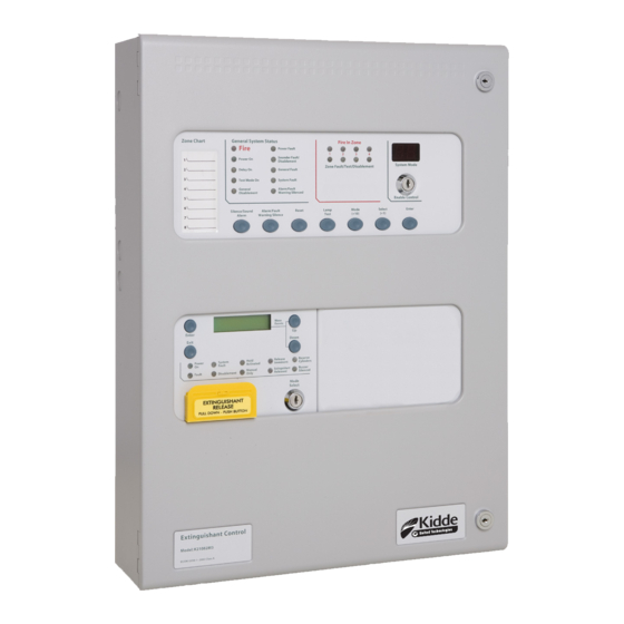
Control Panel Fascias This drawing shows the fascias of the models available in the FireBeta XT+ range. 23911-K087(4+1) 23911-K085 (4+2) 23911-K088 (8+2) 23911-K089 (8+3) 23911-K090 (8+4) The fascias are divided into sections for the detection panel and extinguishing modules. A standard EN54-2 control and indicating equipment section with up to eight zones is located in the top aperture of the panel fascia and EN12094-1 extinguishing modules are fitted in the lower apertures. -
Page 13: Removing The Detection Module
Removing the Detection Module Open the control panel lid using the two 801 lock keys. Before the chassis can be removed it will be necessary to disconnect the power connector terminal block on the left hand side of the PCB. This is fitted on pins and can be pulled towards you to remove it. Do not remove the wires from the terminals. -
Page 14: Connecting To The Circuit Boards
Connecting to the Circuit Boards All connections for field wiring are to rows of terminals along the top and bottom of the circuit boards. Shielded fire alarm cable such as FP200 and metal cable glands must be used for all connections to the panel. -
Page 15: Sounder Circuit Wiring
Sounder Circuit Wiring All sounders must be polarised type, if non-polarised sounders are used the control panel will permanently show a fault condition. See table 4 for a list of compatible sounder types. Sounder circuits are monitored for open and short circuit faults, by placing a 10K 0.25W end of line monitoring resistor across the last device on the circuit. - Page 16 Detection zone wiring through an MTL5061 galvanic isolator Detection zone wiring through an MTL778ac I.S. barrier TM204 16 of 56 Issue 1.1...
-
Page 17: Monitored Inputs
Monitored Inputs Monitored inputs (Mode Select, Manual Release, Hold, Abort, Released Pressure Switch and Low Pressure Switch) have the same characteristics as detection zone inputs and require a 6K8 0.5W end of line monitoring resistor and a nominal, 470 ohm 1 W trigger resistor. Example of wiring to a monitored input Extinguishing Output The Extinguishing output is capable of supplying up to 1 Amp for the maximum duration to a solenoid or... -
Page 18: Igniting Actuator Wiring
5.5.2 Igniting Actuator Wiring A maximum of four igniting actuators can be wired in series. If only one or two actuators are fitted, a 2R2, 2.5 Watt resistor must be wired in series with them to provide the correct monitoring resistance. The end of line diode can be discarded when igniting actuators are used. -
Page 19: Remote Inputs
Press the ENTER button and then the (+) button repeatedly until the LCD displays: The XXX displayed here is the previous (factory level) to which the monitoring level had been sent. Press the ENTER button. The LCD will now show: The XXX shown here is the current monitoring level detected on the extinguishing input. -
Page 20: Aux 24V Dc Supply Outputs - Extinguishing Module
Aux 24V DC Supply Output – Extinguishing Module The terminals for the Aux 24V supply are labelled Aux 24V + and R0V. The R0V terminal is the negative terminal. It is possible to have the Aux24V supply outputs removed for a few seconds when the panel is reset. Aux 24V not removed upon reset is set as default on the extinguishing modules. -
Page 21: Common Fault Relay - Detection Module
5.8.1 Common Fault Relay – Detection Module The common fault relay is normally energised and will de-energise upon any fault condition on the detection part or the extinguishing part of the control panel, including total loss of power. The fault relay can be disabled by setting configuration option 22 at Access Level 3, as shown in Table 6 - Detection module configuration options. -
Page 22: Released Relay - Extinguishing Module
5.8.7 Released Relay – Extinguishing Modules The released relay on the extinguishing module will operate when the module enters the released condition, either by being activated automatically via detection zones or by being activated by a manual release input. The released relay will also operate if the panel enters the released condition via the released pressure switch input. - Page 23 When fitting status indicators or ancillary boards, link LK2 must be removed from the rear of the extinguishing module. The last status indicator connected to the serial bus will have a terminating link fitted as described in manuals TM202 and TM203. Rear view of extinguishing module Each status indicator and ancillary board has a 3-bit DIL switch and must be allocated a unique address between 1 and 7.
-
Page 24: Adding New Status Indicators/Ancillary Boards
Adding New Status Indicators/Ancillary Boards When the system is powered, it will search for connected status indicators and/or ancillary boards connected to Extinguishing modules. If status indicators or ancillary boards are fitted and detected by the control panel, the LCD will display: X = the number of faults Press ENTER on the module to which the status indicators or ancillary boards are connected with the ENABLE CONTROL keyswitch off and use the (+) button on the module to view the faults. -
Page 25: Removing Status Indicators/Ancillary Boards
With the ENABLE CONTROL keyswitch off, the LCD will display: When additional status indicators or ancillary boards are added to the system, these will be shown on the LCD of the extinguishing module when the system is powered up, or the processor reset switch is pressed on the module to which the status indicators or ancillary board is connected. -
Page 26: Configuring The Firebeta Xt
Full details of status units and ancillary boards can be found in TM202, TM203 and TM206. Wiring to status units and ancillary boards Configuring the FireBeta XT+ Detection Module FireBeta XT+ extinguishing control panels consist of 2 parts. The detection part has 2, 4 or 8 detection zones and has a number of configuration options, which can be set at commissioning to suit the requirements of the installation. - Page 27 When the required code number is displayed, pressing the ENTER button will cause the dot on the units seven segment display to flash. This indicates that a configuration option has been set. To review which configuration options have been set previously, simply scroll through numbers 1 to 99, A1 to A8, C1 to C8 and E1 to E8 and those with a flashing dot indicate which options have been set.
- Page 28 Code Function Comments COINCIDENCE ZONE 1 COINCIDENCE ZONE 2 COINCIDENCE ZONE 3 COINCIDENCE ZONE 4 Zone contributes to ancillary board coincidence O/P. Any number of zones can be selected to contribute. COINCIDENCE ZONE 5 COINCIDENCE ZONE 6 COINCIDENCE ZONE 7 COINCIDENCE ZONE 8 CONFIGURE Z1 FOR I.S BARRIER CONFIGURE Z2 FOR I.S BARRIER...
-
Page 29: Extinguishing Module
Code Function Comments ZONE 4 WILL NOT OPERTATE FIRE RELAY Enables individual zones to be selected to not operate the fire ZONE 5 WILL NOT OPERTATE FIRE RELAY relay. This is sometimes combined with the non-latching function ZONE 6 WILL NOT OPERTATE FIRE RELAY to prevent ring around on interconnected panels ZONE 7 WILL NOT OPERTATE FIRE RELAY ZONE 8 WILL NOT OPERTATE FIRE RELAY... -
Page 30: Activation Zones
Press the ENTER button and the display will show: Press the ENTER button to select single zone activation mode. To save the settings, slide the WRITE ENABLE switch gently to the right. Operation of any detection zone in the range of zones selected to trigger the extinguishing module will put the extinguishing module into the activated condition. -
Page 31: Pre-Release Delay Timer
To change the reset inhibit time, switch on the ENABLE CONTROL keyswitch and slide the WRITE ENABLE switch on the module to be configured gently to the left. Press the ENTER button on the extinguishing module then press the (+) button until the display shows: Press the ENTER button and the display will show: To change the reset inhibit time, press (+) or (-) buttons until the time required is displayed and then press ENTER. -
Page 32: Nd Stage Alarm
To change the time, press the (+) or (-) buttons until the required time is displayed To save the settings, slide the WRITE ENABLE switch gently to the right. The extinguishing release time will now be set to the chosen value. 7.2.7 Stage Alarm The second stage alarm output can be configured to be steady or pulsing at about 1 second on, 1... -
Page 33: Delay On Manual Release
7.2.9 Delay on Manual Release The manual release function (panel mounted and remote) can be configured to have a pre-release time delay (as per the set pre-release time) or to have no pre-release delay allowing immediate operation of the extinguishing output when a manual release is operated. The factory default setting for this is for the manual release to have a delay time the same as the pre- release delay. -
Page 34: Release Timer
7.2.11 Release Timer The release timer can be disabled such that once the extinguishing output has operated; it remains operated until the system is reset. To disable the release timer, switch on the ENABLE CONTROL keyswitch and slide the WRITE ENABLE switch on the module to be configured gently to the left. -
Page 35: Disable Fault Output
Press the ENTER button and the display will show: To select this option, press the ENTER button. To save the settings, slide the WRITE ENABLE switch gently to the right. The earth fault monitoring facility on the module will now be disabled. 7.2.14 Disable Fault Output The fault output relay can be disabled on each module individually. -
Page 36: Extinguishing Output Monitoring Levels
To select this option, press the ENTER button. To save the settings, slide the WRITE ENABLE switch gently to the right. The low pressure switch input will now require a normally closed contact with a 470R trigger resistor and 6K8 end of line resistor for correct supervision. 7.2.16 Extinguishing Output Monitoring Levels The extinguishing outputs are able to monitor both solenoid and igniting actuator release devices. -
Page 37: Panel Operation - Access Levels 1 And
Panel Operation – Access Levels 1 and 2 Normal Condition Under normal conditions and with all modules in Manual & Auto mode, control panels will have only the green, Power On LED lit on the detection and extinguishing modules. With the ENABLE CONTROL keyswitch off, the display on the detection part of the panel will be blank and, the LCDs on the extinguishing modules will show: Any modules that are in Manual Only mode will have an additional, Manual only yellow LED lit and their... -
Page 38: Disable Sounder Outputs
The 7 segment display will show (test zone 1), press the MODE button and the display will show To disable zone 1 press the ENTER button. The display will show and the yellow Disablement LED will be lit. To select further zones to disable, press the SELECT button and then the ENTER button so that the flashing dot appears next to the selected display e.g. -
Page 39: Disable Stage 1 Output
The display will show: Press the ENTER button to toggle this function. The yellow Disabled LED on the module that has been disabled will be lit. Turn the ENABLE CONTROL keyswitch off to leave the disablement active. To re-enable the extinguishing outputs repeat the procedure above. -
Page 40: Disable Released Output
The yellow Disabled LED on the module that has been disabled will be lit. Turn the ENABLE CONTROL keyswitch off to leave the disablement active. To re-enable the stage 2 relay output repeat the procedure above. 8.3.5 Disable Released Output To disable the released relay output, press the (+) button on the module while at Access Level 2 until the display shows: Press the ENTER button to select this function. -
Page 41: Single Zone Fire Condition
Note: The extract output does not turn off when the module is reset. Single Zone Fire Condition Upon receipt of a fire condition by activation of a detector or call point, the Common Fire indicator on the detection module will light, the fire buzzer will sound and the zonal Fire indicator(s) will flash at around 2Hz. -
Page 42: Reset
Note: Pressing the SILENCE/SOUND ALARM button whilst the control panel is in the silenced condition will cause the sounders to operate again. The sounders can be toggled on and off with the Silence/Sound alarm button as required. Reset To reset the panel, insert the ENABLE CONTROL key, turn to the right then press the RESET button. The extinguishing module will reset only after the reset inhibit timer has expired once the activated condition has been established. -
Page 43: General Fault
8.13 General Fault – Detection Module The general fault LED will illuminate under any fault condition. This LED will also light if the WRITE ENABLE switch has been left in the Access Level 3 position and the ENABLE CONTROL keyswitch is turned off. 8.14 Lamp Test All LED indicators on the detection module can be tested at any time by pressing the Lamp Test button. -
Page 44: Manual Release
8.19 Manual Release Extinguishing modules may be manually activated by one of the following: • The manual release control on the front of the module • A remotely mounted manual release callpoint connected to the monitored manual release inputs • A manual release control mounted on a status indicator. -
Page 45: Extinguishing Module
Internal controls on detection part of control panel PROC W/ DOG WRITE RESET RESET ENABLE Extinguishing Modules 9.2.1 Watchdog Reset If the microprocessor on an extinguishing module fails to carry out its operation correctly it will attempt to restart. If a watchdog event occurs, the extinguishing module will show Fault and System Fault LEDs along with CPU fault. -
Page 46: Write Enable Switch
9.2.4 Write Enable Switch It is necessary to protect the configuration memory of the extinguishing module while the system is running normally. To do this a memory Write Enable switch is provided on each module. The memory Write Enable switch must be switched on before any changes can be made to the configuration. The Write Enable switch can be fragile and should be operated with care. -
Page 47: Internal Indications
10 Internal Indications 10.1 Detection Module To assist in identifying fault conditions which are not detailed on the front of the control panel, a number of internal indicators are visible with the control panel door open as follows: 10.1.1 Mains Fail Indicates that the 230V AC supply is not present and the system is running on standby batteries. -
Page 48: Power Supply
10.1.10 S2 Fault Indicates a short or open circuit on sounder output S2. Check sounder circuit wiring, if wiring is OK remove cables from the panel sounder circuit and fit EOL resistors into the terminals. If the fault clears re-check sounder circuit wiring and sounders, if the fault remains replace the panel PCB. 10.2 Extinguishing Modules 10.2.1 Watchdog... - Page 49 The tables below can be used to calculate the loading for all models by adding the loads in the second column. 23911-K087 - 4 zone single area Current in milliamps Detection section max alarm load Extinguishing module max alarm load Detection section total sounder load (S1&S2) Detection section Aux 24V supply Extinguishing module total sounder load...
- Page 50 23911-K088 - 8 zone three area Current in milliamps Detection section max alarm load Extinguishing module 1 max alarm load Extinguishing module 2 max alarm load Extinguishing module 3 max alarm load Detection section total sounder load (S1&S2) Detection section Aux 24V supply Extinguishing module 1 total sounder load Extinguishing module 2 total sounder load Extinguishing module 3 total sounder load...
-
Page 51: Maintenance
The maximum capacity batteries that should be fitted are 7Ah for the 4+1, 4+2, 8+2 models and 17Ah for the 8+3 and 8+4 models. The maximum current drawn from the batteries when the main power source is disconnected, is 3 Amps for the 4+1, 4+2 and 8+2 models and 4 Amps for the 8+3 and 8+4 models. -
Page 52: Commissioning Instructions
14 Commissioning Instructions Before applying power to the panel, any solenoids or igniting actuators must be physically isolated from the panel by disconnecting both wires, this will prevent any accidental release of extinguishant. When power is applied and all connections are correct, only the green Power On and either the Automatic/Manual or Manual Only indicators should be lit. - Page 53 ZONE 4 ALARM FROM CALL POINT DELAYED ZONE 5 ALARM FROM CALL POINT DELAYED ZONE 6 ALARM FROM CALL POINT DELAYED ZONE 7 ALARM FROM CALL POINT DELAYED ZONE 8 ALARM FROM CALL POINT DELAYED COINCIDENCE ZONE 1 COINCIDENCE ZONE 2 COINCIDENCE ZONE 3 COINCIDENCE ZONE 4 COINCIDENCE ZONE 5...
- Page 54 ZONE 6 ANY ALARM DELAYED ZONE 7 ANY ALARM DELAYED ZONE 8 ANY ALARM DELAYED ZONE 1 SOUNDERS INHIBITED ZONE 2 SOUNDERS INHIBITED ZONE 3 SOUNDERS INHIBITED ZONE 4 SOUNDERS INHIBITED ZONE 5 SOUNDERS INHIBITED ZONE 6 SOUNDERS INHIBITED ZONE 7 SOUNDERS INHIBITED ZONE 8 SOUNDERS INHIBITED ZONE 1 WILL NOT OPERTATE FIRE RELAY ZONE 2 WILL NOT OPERTATE FIRE RELAY...
- Page 55 Extinguishing module 2 CONFIGURATION OPTION WRITE SETTING EXTINGUISHING OUTPUT MODE = ACTIVATION MODE = FIRST ACTIV. ZONE = LAST ACTV. ZONE = RESET INHIBIT TIME = PRE-REL. DELAY TIME = EXTING. RELEASE TIME = PULSED ACTIV. ALARMS ? STEADY ACTIV. ALARMS ? RELEASED IND.
- Page 56 FAULT OUTPUT DISABLED ? LOW PRESS. I/P NORMAL ? LOW PRESS. I/P INVERTED ? EXTING. O/P 1 LEVEL ? EXTING. O/P 2 LEVEL ? Extinguishing module 4 CONFIGURATION OPTION WRITE SETTING EXTINGUISHING OUTPUT MODE = ACTIVATION MODE = FIRST ACTIV. ZONE = LAST ACTV.