
Related Manuals for ABB 266 HART


Summary of Contents for ABB 266 HART
- Page 1 Operating Instruction OI/266/HART-EN Rev. D 2600T Series Pressure Transmitters 266 Models HART 2600T Series Pressure Transmitters Engineered solutions for all applications...
-
Page 2: Table Of Contents
266 Models - HART Table of contents Process connection considerations ........23 Introduction ..............4 Kynar inserts connection ........... 23 Instruction manual structrure ..........4 Installation recommandations ..........24 Models covered by this manual .......... 4 Worlwide Service Support Centers ........4 Transmitter wiring .............. - Page 3 Custom linearization curve ..........57 Bidirectional Flow ............57 Cylindric lying tank ............57 Spherical tank ..............57 Configuration with the PC / laptop or HHT ......57 Configuration with graphical user interface ......59 Error messages ..............59 LCD display ..............59 Error states and alarms .............
-
Page 4: Introduction
ABB instrumentation products are supported worldwide by the local ABB Instrumentation branches. In case you fail to get in touch with your country ABB Instrumentation office you may want to get in touch with one of the following center of excellence for ABB Pressure products. -
Page 5: Safety Notes
– Training or instruction in accordance with safety engineering standards regarding maintenance and use of adequate safety systems For safety reasons, ABB draws your attention to the fact that only sufficiently insulated tools conforming to DIN EN 60900 may be used. -
Page 6: Improper Use
Repairs, alterations, and enhancements, or the installation of replacement parts, are only permissible as far as these are described in the manual. Approval by ABB must be requested for any activities beyond this scope. Repairs performed by ABB-authorized centers are excluded from this. -
Page 7: Operator Liability
EN ISO 9001:2000, EN ISO 14001:2004, and OHSAS 18001. Our products and solutions are intended to have minimum impact on the environment and persons during manufacturing, storage, transport, use and disposal. This includes the environmentally friendly use of natural resources. ABB conducts an open dialog with the public through its publications. -
Page 8: Saferty Information For Inspection And Maintenance
266 Models - HART Safety information for inspection and maintenance Warning – Risk to persons Warning – Risk to persons There is no EMC protection or protection against accidental contact The device can be operated at high pressure and with aggressive when the housing cover is open. -
Page 9: Transmitter Overview
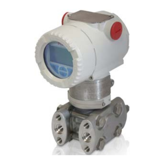
Transmitter overview Transmitter components overview Figure 1: Differential pressure transmitter components 1 - TTG display (L5 option) 2 - LCD display (L1 option) Important These two pictures show only two different kinds of transmitters equipped with Barrel type housing. Please consider that DIN housings are available. -
Page 10: Range And Span Consideration
FM09ATEX0025X (Ex nL) CE-Identification number of the notified bodies to Pressure Equipment Directive: 0474, to ATEX certification: 0722 The certification plate (ref.A) shown here may also be issued for ABB-APR, 32425 Minden, Germany, with the numbers: FM09ATEX0068X (Ex d) FM09ATEX0069X (Ex ia) -
Page 11: Optional Wired-On Sst Plate (I1)
ABB S.p.A. SERIAL\NUMBER Made in Italy PRODUCT CODE SEAL-L SEAL-H SPEC.REQUEST HW Rev. SENSOR DIAPH.-FILL FLANGE/CONN.-GASKET/S H DIAPH.-FILL L DIAPH.-FILL PED: POWER SUPPLY OUTPUT SIGNAL MWP/OVP LRL/URL SPAN LIMITS Local keys below label Calib. Range 2600T Number PRESSURE TRANSMITTER General Purpose IP67 Max.Supply Voltage 42 Vdc II 1/2 G Ex d IIC T6 - II 1/2 D Ex tD A21 IP67 T85°C FM09ATEX0023X - IECEx FME09.0002X... -
Page 12: Mounting
The 266 pressure transmitter in your hands has been factory calibrated to reflect the published declared performance specification; no further calibration is required in normal condition. ABB typically configures 266 pressure transmitters according to the user requirements. A typical configuration includes: – TAG number –... -
Page 13: Hazardous Area Consideration
Pressure Equipment Directive (PED) (97/23/CE) Devices with PS >200 bar Devices with a permissible pressure PS >200 bar have been subject to a conformity validation. The data label includes the following specifications: SERIAL\NUMBER ABB S.p.A. Made in Italy PRODUCT CODE SEAL-L SEAL-H SPEC.REQUEST HW Rev. -
Page 14: Bracket Mounting
266 Models - HART It is important to mount the transmitter and to lay the process piping so that gas bubbles, when measuring liquids, or condensate when measuring gases, will flow back to the process and not enter the transmitter measuring chamber. Optional Vent/drain valves (code V1/V2/V3) on the transmitter are located on the sensor flanges. - Page 15 29 (1.14) 18 (0.71) 58 (2.28) 55 (2.17) 18 (0.71) 9 (0.35) 91 (3.58) 66 (2.60) with plug 78 (3.07) with d/v valve 54 (2.13) 96.8 (3.81) 102 (4.02) 29 (1.12) 100 (3.94) for NACE bolting Figure 7b: Differential Pressure Style transmitter (High Static option) 29 (1.14) 18 (0.71) 58 (2.28)
- Page 16 266 Models - HART 29 (1.14) 18 (0.71) 72 (2.83) 87 (3.42) 116 (4.57) 55 (2.17) 183 (7.19) 136 (5.35) Figure 9: Differential Pressure Style transmitter with DIN housing installed on a Vertical pipe with optional bracket (B2) installation for AIR/GAS measurements 29 (1.14) 18 (0.71) 116 (4.57)
- Page 17 29 (1.14) 18 (0.71) 58 (2.28) 55 (2.17) 18 (0.71) 91 (3.58) 72 (2.83) 54 (2.13) 113 (4.45) 116 (4.57) Figure 11: Differential Pressure Style transmitter with barrel housing and Kynar inserts installed on a horizontal pipe with optional bracket (B2) 29 (1.14) 18 (0.71) 58 (2.28)
-
Page 18: B2 Pipe And Wall Mounting Bracket Details
266 Models - HART B2 Pipe and wall mounting bracket details All the bolts and nuts supplied are necessary for the installation on pipe. In case a panel or wall installation will be done, the U-bolt and the U-bolt nuts and washers will not have to be used. The bolts for panel mounting are not within the scope of supply. -
Page 19: B5 Flat Type Bracket Details
B5 Flat type bracket details 1 - U-bolt 2 - U-bolt fixing bolt and washer 3 - Transmitter fixing bolts 4 - B5 bracket Figure 15: Flat type mounting bracket kit (B5) Mounting a P style pressure transmitter (266G, 266A, 266H, 266N) The pressure transmitter can be mounted directly on the manifold. -
Page 20: B1 And B2 Barrel Housing Bracket Details
266 Models - HART 111 (4.37) 29 (1.14) 18 (0.71) 18 (0.71) 91 (3.58) 1/2 - 14 NPT Ø65 (2.56) CH 22 70 (2.75) 140 (5.54) Figure 17: Model 266G or 266A P-Style transmitter with barrel housing installed on a 2”pipe with optional bracket (B1 carbon steel or B2 Stainless Steel 316L) B1 and B2 Barrel housing bracket details 1 - U-bolt 2 - U-bolt fixing bolt and washer... -
Page 21: B2 Din Housing Bracket Details
128 (5.04) 29 (1.14) 122 (4.80) 30 (1.19) 85 (3.35) 18 (0.71) 18 (0.71) 66 (2.60) 72 (2.83) 1/2 - 14 NPT Ø65 (2.56) 32 (1.26) width across 117 (4.60) flats of exagon 49 (1.93) 105 (4.13) Figure 19: Model 266H or 266N Hi overload resistant P-Style transmitter with DIN housing installed on a 2”pipe with optional bracket (B2 Stainless Steel 316L) 128 (5.04) 29 (1.14) 120 (4.72) -
Page 22: Transmitter Housing Rotation
266 Models - HART Transmitter housing rotation Impulse piping connection for standard instruments To improve field access to the wiring or the visibility of the In order for the pipes to be laid correctly, the following points optional LCD meter, the transmitter housing may be rotated must be observed: through 360°... -
Page 23: Process Connection Considerations
Process connections considerations 266 differential pressure transmitter process connections on the transmitter flange are 1/4 - 18 NPT, with a centers distance of 54mm (2.13in) between the connections. The process connections on the transmitter flange are on centers to allow direct mounting to a three-valve or five-valve manifold. -
Page 24: Installation Recommandations
266 Models - HART Installation recommendations Impulse piping configuration depends on the specific measurement application. Steam (condensable vapor) or clean liquids flow measurement – Place taps to the side of the line. – Mount beside or below the taps. – Mount the drain/vent valve upward. –... - Page 25 Liquid Level Measurements on closed tanks and non condensable fluids (dry leg) – Mount the transmitter at the same height or below the lowest level to be measured. – Connect the + (H) side of the transmitter to the bottom of the tank.
- Page 26 266 Models - HART Liquid Level Measurement with open tanks – Mount the transmitter at the same height or below the lowest level to be measured. – Connect the + (H) side of the transmitter to the bottom of the tank.
- Page 27 Pressure or absolute pressure measurement of a liquid in a pipe – Place the tap at the side of the line. – Mount the transmitter beside or below the tap for clean fluids, above the tap for dirty fluids. – Connect the + (H) side of the transmitter to the pipe. Dirty fluids Dirty fluids Clean fluids...
-
Page 28: Transmitter Wiring
266 Models - HART Pressure or absolute pressure measurement of a gas in a pipe – Place the tap at the top or side of the line. – Mount the transmitter beside or above the tap. – Connect the transmitter to the pipe. Figure 34: Gauge or absolute pressure measurement of gas in a pipe with DP and P style transmitter Transmitter wiring Warning - General risks... -
Page 29: Analogue Output (Hart) Transmitter Wiring
Important With Category 3 transmitters for use in “Zone 2”, a qualified cable gland for this type of protection must be installed by the customer (see the section “Hazardous Area Consideration”). An M20 x 1.5 threads is located in the electronics housing for this purpose. For transmitters with “Flameproof enclosure”... -
Page 30: Wiring Procedure
266 Models - HART The actual possible line length of the electrical circuit depends on the total capacitance and resistance, and can be estimated using the following formula: Where: L = Line length in meters – 65 x 10 + 10000 R = Total resistance in Ω... -
Page 31: Grounding
Assembling and connecting the socket connector The socket connector for connecting the cable is supplied unassembled as an accessory for the transmitter. – The contacts (2) are crimped or soldered onto the cable ends (wire cross section of 0.75 … 1 mm2 (AWG 18 … AWG 17)), from which approx. -
Page 32: Commissioning
A current that is < 4 mA or > 20 mA may also indicate that the microprocessor has detected an internal error. In this case the alarm output can be configured both via the local LCD or via an external Hart hand held terminal (ABB 691HT, DHH801 etc) or via a DTM based configuration tool (Asset Vision). -
Page 33: Write Protect
Write Protection Write protection prevents the configuration data from being overwritten by unauthorized users. If write protection is enabled, the “Z” and “S” buttons are disabled. However, it is still possible to read out the configuration data using the graphical user interface (DTM) or another, similar communication tool. -
Page 34: Installing/Removing The External Pushbuttons
266 Models - HART Installing/Removing the external pushbuttons – Loosen the screws that fix the nameplate plate and slide the plate to gain access to the local adjustments. – Loosen the pushbuttons assembly screws (1) holding down the plastic element which is spring loaded. –... -
Page 35: Factory Settings
Factory settings Transmitters are calibrated at the factory to the customer’s specified measuring range. The calibrated range is provided on the name plate whereas the tag number on the additional tag plate. The calibrated range and tag number are provided on the name plate. If this data has not been specified, the transmitter will be delivered with the following configuration: Important Factory setting... -
Page 36: Correction Of Zero Shift (Zero Bias / Offset)
266 Models - HART Important This configuration procedure only changes the 4 … 20 mA current signal; it does not affect the physical process pressure (PV value) also shown on the digital display or user interface. To avoid potential discrepancies, you can use follow the procedure below. After performing a correction, you must check the device configuration. -
Page 37: Lcd (L1) Activation Considerations
LCD (L1 option) activation considerations Gain access to the display by unscrewing the windowed cover. Please observe the Hazardous area prescription before proceeding with the cover removal. For activation, see instructions below. Through The Glass (TTG) (L5 option) activation considerations The TTG technology allows the user to activate the keypad on the HMI without the need of opening the windowed cover of the transmitter. - Page 38 266 Models - HART This menu allows the parameterization of the process alarm. The menu driven structure will guide you through the choice of the fail safe functions such as the saturation limits and the fail level (upscale or downscale). This menu allows the local calibration of the instrument.
-
Page 39: Easy Set-Up
Easy Set-up Press key (4) and select the language. After entering the settings, press key (1) to move to the next menu item. Once in the alphabetic menu use Next (1) key to position the cursor on the character that you want to change. -
Page 40: Device Set-Up
266 Models - HART Device Set-up 40 OI/266/HART-EN Rev. D | 2600T Series Pressure transmitters... - Page 41 2600T Series Pressure transmitters | OI/266/HART-EN Rev. D 41...
- Page 42 266 Models - HART 42 OI/266/HART-EN Rev. D | 2600T Series Pressure transmitters...
- Page 43 2600T Series Pressure transmitters | OI/266/HART-EN Rev. D 43...
-
Page 44: Display
266 Models - HART Display 44 OI/266/HART-EN Rev. D | 2600T Series Pressure transmitters... - Page 45 2600T Series Pressure transmitters | OI/266/HART-EN Rev. D 45...
- Page 46 266 Models - HART 46 OI/266/HART-EN Rev. D | 2600T Series Pressure transmitters...
-
Page 47: Process Alarm
Process Alarm This menu allows the complete configuration of the analogue output in case of saturation and alarm. The output signal will range from 4 to 20 mA in case the process variable is within the calibrated span limits. In case the process variable (PV) will be below the LRV (lower range value) the signal will be driven to the “Low Saturation”... -
Page 48: Calibrate
266 Models - HART Calibrate 48 OI/266/HART-EN Rev. D | 2600T Series Pressure transmitters... -
Page 49: Totalizer
Totalizer 2600T Series Pressure transmitters | OI/266/HART-EN Rev. D 49... - Page 50 266 Models - HART 50 OI/266/HART-EN Rev. D | 2600T Series Pressure transmitters...
- Page 51 2600T Series Pressure transmitters | OI/266/HART-EN Rev. D 51...
-
Page 52: Diagnostics
266 Models - HART Diagnostics 52 OI/266/HART-EN Rev. D | 2600T Series Pressure transmitters... -
Page 53: Device Info
Device Info 2600T Series Pressure transmitters | OI/266/HART-EN Rev. D 53... -
Page 54: Communication
266 Models - HART Communication 54 OI/266/HART-EN Rev. D | 2600T Series Pressure transmitters... -
Page 55: Damping
Damping (DAMPING) Pressure transmitter output signals that are noisy as a result of the process can be smoothed (damped) electrically. The additional time constant can be set between 0 s and 60 s in increments of 0.0001 s. Damping does not affect the value shown on the digital display as a physical unit. -
Page 56: Square Root To The 3Rd Power
266 Models - HART Figure 46: Square-Root transfer functions Square root to the 3rd power The x3 Square root Transfer function can be used for open channel (see figures on the right) flow measurement using ISO 1438 rectangular weirs (Hamilton Smith, Kindsvater-Carter, Rehbock formulas) or trapezoidal weirs (Cippoletti formulas) and ISO 1438 Venturi flumes. -
Page 57: Bidirectional Flow
The 266 transmitters can be configured by either one of the following device. - Hand Held terminals like the ABB 691HT, ABB DHH800-MFC, Emerson Process 375 and 475 provided the 266 EDD has been downloaded and enabled in the terminal. - Page 58 266 Models - HART You can use a handheld terminal to read out or configure/calibrate the transmitter. If a communication resistor is installed in the connected supply unit, you can clamp the handheld terminal directly along the 4 ... 20 mA line. If no communication resistor is present (min.
-
Page 59: Configuration With Graphical User Interface
“File_Save”. Configuration with the graphical user interface (DTM) System requirements – Operating control program (e.g., ABB Asset Vision Basic version 1.00.17 or higher) – DTM (Device Type Manager; graphical user interface) – Operating system (depending on the respective control program) To operate the Asset Vision Basic please refer to the relevant operating instruction. -
Page 60: Error States And Alarms
266 Models - HART Error states and alarms Error list – Communication Board / Electronic related error messages. Error message Tx LCD message Possible cause Suggested action Tx response F116.023 Electronic Memory Failure Electronic memory corrupted The electronic must be replaced Analog Signal to Alarm The output circuit could be broken A DAC (digital to outpt converter) trimming... - Page 61 – Configuration related error messages. Error message Tx LCD message Possible cause Suggested action Tx response Input Simulation The P-dP Value produced in output is Use a HART configurator (DTM - Hand held) to place C088.030 Active derived by the value simulated in input device back in to normal operating mode (Remove the no effect input simulation)
- Page 62 266 Models - HART – Process related error messages. Error message Tx LCD message Possible cause Suggested action Tx response This effect could be produced by other equipment on the pro- The compatibility of pressure trans- F104.032 Pressure Overrange cess, (valves…..). Exceeding the pressure range can cause mitter model and process conditions no effect reduced accuracy or mechanical damage to the diaphragm...
-
Page 63: Maintenance
The use of non original spare parts makes the warranty void. In case you want ABB to perform the repair, please send back the transmitter to your local ABB office complete with the return form that you find in this manual appendix and include it with the device. -
Page 64: Removing/Installing The Process Flanges
266 Models - HART Removing/Installing the process flanges – Slacken the process flange screws by working on each in a crosswise manner (hexagon head, SW 17 mm (0.67 inch) for 266DS/266PS/266VS or SW 13 mm (0.51 inch) for 266MS/266RS). – Carefully remove the process flange, making sure that the isolating diaphragms are not damaged in the process. –... -
Page 65: Pressure Transducer Replacement
Pressure transducer replacement If the pressure transducer needs to be replaced proceed as follows: – Insulate the transmitter from the process by acting on the manifolds or on the insulation valves – Open the vent valves to allow sensor depressurization –... -
Page 66: Hazardous Area Consideration
266 Models - HART Hazardous Area considerations Ex Safety aspects and IP Protection (Europe) According to ATEX Directive (European Directive 94/9/EC of 23 March 1994) and relative European Standards which can assure compliance with Essential Safety Requirements, i.e., EN 60079-0 (General requirements) EN 60079-1 (Flameproof enclosures “d”) EN 60079-11 (Equipment protection by intrinsic safety “i”) EN 60079-26 (Equipment with equipment protection level -EPL- Ga) EN 61241-0 (General requirements) EN 61241-1 (Protection by enclosures “tD”) EN 61241-11 (Protection by intrinsic safety”iD”) the pressure transmitters of the 2600T SERIES have been certified for the following group, categories, media of dangerous atmo-... - Page 67 b) Certificate ATEX II 1/2 G Ex ia IIC T4/T5/T6 and II 1/2 D Ex iaD 21 T85°C FM Approvals certificate number FM09ATEX0024X (Lenno products) and FM09ATEX0069X (Minden products) Important This ATEX Category depends on the application (see below) and also on the intrinsic safety level of the transmitter supply (associated apparatus) which can sometimes suitably be [ib] instead of [ia].
- Page 68 266 Models - HART c) Certificate ATEX II 1/2 G Ex d IIC T6 ATEX II 1/2 D Ex tD A21 IP67 T85°C (-50°C ≤ Ta ≤+75°C) FM Approvals Certificate number FM09ATEX0023X (Lenno products) and FM09ATEX0068X (Minden products) The meaning of ATEX code is as follows: II: Group for surface areas (not mines) 1/2: Category - It means that only a part of the transmitter complies with category 1 and a second part complies with category 2 (see next application sketch).
- Page 69 A22 IP67 T85°C. FM Approvals Certificate number FM09ATEX0025X (Lenno products) and FM09ATEX0070X (Minden products) Important Important It is the technical support for the ABB Declaration of Conformity When installed this transmitter must be supplied by a voltage limiting device which will prevent the rated voltage of 42 V d.c.
-
Page 70: Entities For L5 Optional Integral Lcd Display
266 Models - HART Entities for “L5” option integral LCD display (with TTG technology) HART Version with “L5” option (display with TTG technology) Ui= 30Vdc Ci= 5nF Li= uH Temperature Class - Gas Temperature Class - Dust Minimum amb. °C Maximum amb. °C Imax mA Power W T135°C... -
Page 71: Additional Instruction For Iec 61508 Certified Device
Additional instruction for IEC61508 certified device (digits 8 or T under “output” options) Safety philosophy The 266 Pressure Transmitters are field devices designed according to the requirements of the standard IEC61508 for the Safety Related Systems. Standard currently used focus on individual parts of all the safe instrumentation used to implement a safety function. -
Page 72: System Safety Requirement Assignment
266 Models - HART System safety requirement assignment I/O system response time The total system response time is determined by the following elements: - Sensor detection time, - Logic solver time; - Actuator response time; The total system response time must be less than the process safety time. To ensure a safe operation of the system, the scan rate of each section of the logic solver multiplied by the number of channels shall be taken into account together with the safety time of actuator and sensor response time. -
Page 73: Architecture Description And Principle Of Operation
Architecture description and principle of operation The instrument consists of two main functional units: – Primary unit – Secondary unit The pressure transducer unit includes the process interface, the sensor and the front-end electronics; the Secondary Unit includes the electronics, the terminal block and the housing. The two units are mechanically coupled by a threaded joint. Principle of operation The principle of operation is as follows. -
Page 74: Safety-Related Parameters
266 Models - HART In case the tests would fail the transmitter will drive the output to the alarm values. In this case a correction action consists in the re-calibration of the D/A converter. In case the normal functionality will be not re-established, the transmitter shall be considered failed and not possible to use. -
Page 75: Trouble Sheet
Shipping information for the return of the equipment Material returned for factory repair should be sent to the nearest ABB Service Center; transportation charges prepaid by the Purchaser Please enclose this sheet duty completed to cover letter and packing list... -
Page 76: Control Of Substances Hazardous To Health (C.o.s.h.h.)
Signed Name Position Date ABB S.p.A Process Automation Division Uffici Commerciali / Sales Office: Via Statale, 113 - 22016 Lenno (CO) Italy Tel. +39 0344 58 111 Fax +39 0344 56 278 e-mail: abb.instrumentation@it.abb.com... -
Page 77: Ec Declaration Of Conformity
2600T Series Pressure transmitters | OI/266/HART-EN Rev. D 77... - Page 78 266 Models - HART 78 OI/266/HART-EN Rev. D | 2600T Series Pressure transmitters...
- Page 79 2600T Series Pressure transmitters | OI/266/HART-EN Rev. D 79...
- Page 80 With regard to purchase orders, the agreed For more product information visit: particulars shall prevail. ABB does not accept any www.abb.com responsibility whatsoever for potential errors or possible lack of information in this document.