Sony WM-FX373 Service Manual
Radio cassette player
Hide thumbs
Also See for WM-FX373:
- Operating instructions (2 pages) ,
- Operating instructions (2 pages) ,
- Operating instructions (4 pages)
Advertisement
SERVICE MANUAL
Ver 1.2 2004.03
Dolby noise reduction manufactured under license
from Dolby Laboratories Licensing Corporation.
"DOLBY" and the double-D symbol ; are trade-
marks of Dolby Laboratories Licensing Corporation.
• Frequency range
FM: 65.0 – 107.9 MHz (East European Model)
87.5 – 108 MHz (Italian, Saudi Arabia Model)
87.6 – 108 MHz (US, Canadian Model)
87.6 – 107.9 MHz (Other Model)
AM: 526.5 – 1,606.5 kHz (Italian, Saudi Arabia Model)
530 – 1,710 kHz (US, Canadian Model)
531 – 1,602 kHz (Other Model)
• Power requirements
3V DC batteries R6 (AA) × 2/External DC 3V power sources
• Dimensions
88.5 × 118.6 × 38.2 mm
× 4
× 1
(3
1
/
3
/
9
/
inches) (w/h/d) incl. projecting parts and controls
2
4
16
• Mass
Approx. 170 g (6.0 oz)
Approx. 250 g (8.9 oz) incl. batteries and a cassette
• Supplied accessories
Stereo headphones or Stereo earphones (1)/Belt clip (1)
Design and specifications are subject to change without notice.
Sony Corporation
9-923-344-12
2004C05-1
Personal Audio Company
© 2004.03
Published by Sony Engineering Corporation
WM-FX373/FX375
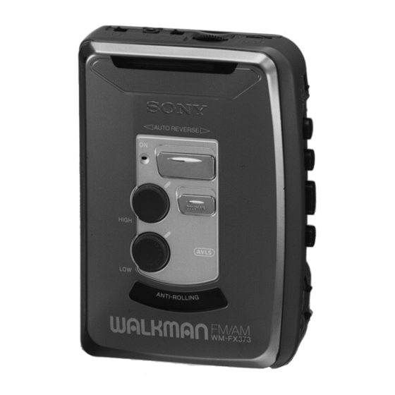
Photo: WM-FX373
SPECIFICATIONS
Canadian Model
Chinese Model
Model Name Using Similar Mechanism
Tape Transport Mechanism Type
RADIO CASSETTE PLAYER
US Model
WM-FX375
Tourist Model
WM-FX373
AEP Model
E Model
WM-FX373/FX375
NEW
MT-WMEX372-114
Advertisement
Table of Contents

Related Manuals for Sony WM-FX373


Summary of Contents for Sony WM-FX373
- Page 1 Approx. 250 g (8.9 oz) incl. batteries and a cassette • Supplied accessories Stereo headphones or Stereo earphones (1)/Belt clip (1) Design and specifications are subject to change without notice. RADIO CASSETTE PLAYER Sony Corporation 9-923-344-12 2004C05-1 Personal Audio Company © 2004.03 Published by Sony Engineering Corporation...
-
Page 2: Table Of Contents
TABLE OF CONTENTS SERVICING NOTES GENERAL ..............2 Notes on chip component replacement • Never reuse a disconnected chip component. DISASSEMBLY • Notice that the minus side of a tantalum capacitor may be dam- ............3 aged by heat. MECHANICAL ADJUSTMENTS ....... -
Page 3: Disassembly
SECTION 2 DISASSEMBLY • This set can be disassembled in the order shown below. CABINET (REAR) MAIN BOARD BELT, MOTOR (M901) MECHANISM DECK ASS’Y MAGNETIC HEAD (HP901) (MT-WMEX372-114) MEGA BASS CASSETTE HOLDER ASS’Y UNIT NOTE FOR INSTALLATION DIAL POINTER SETTING Note: Follow the disassembly procedure in the numerical order given. - Page 4 MECHANISM DECK (MT-WMEX372-114) 2 Remove the mechanism deck (MT-WMEX372-114) to direction of the arrow A . 1 two claws BELT, MOTOR (M901), MAGNETIC HEAD (HP901) 1 belt 3 motor (M901) 5 magnetic head (HP901) 4 two screws (M1.4) 2 two special head screws (M1.4) –...
- Page 5 CASSETTE HOLDER ASS’Y 1 Insert a precision screw driver (1.4 mm flat-blade) vertically in to portion A to release the hinge plate. 2 Portion B to release the hinge plate. 4 spring (torsion) 3 Cassette holder ass’y NOTE FOR INSTALLATION Note: Follow the assembly procedure in the numerical order given.
- Page 6 MEGA BASS UNIT Note for installation: 1 two knobs Check that two switches are latched (rotary) with dolby knob and M/B knob when carrying out installation of the mega bass unit. 2 stopper dolby knob M/B knob 3 two claws 5 flexible board two switches 4 Remove the mega bass...
-
Page 7: Mechanical Adjustments
SECTION 4 SECTION 3 MECHANICAL ADJUSTMENTS ELECTRICAL ADJUSTMENTS PRECAUTION PRECAUTION 1. Clean the following parts with a denatured-alcoholmoistened • Supplied voltage: 2.5 V (DC) swab: • Switch and control position playback head pinch roller NORM CrO2/METAL·ST/MONO switch: NORM·ST capstan rubber belt (EXCEPT US, Canadian, 5E, 6E model) 2. - Page 8 0 dB=1 µV TUNER SECTION AM SECTION FM SECTION Setting: Setting: FM/AM/TAPE (RADIO OFF) switch: AM FM/AM/TAPE (RADIO OFF) switch: FM AM RF Signal FM RF Signal generator Put the lead-wire generator antenna close to the set. MAIN board 0.01 µ F (FM RF-IN) (GND) 30% amplitude modulation by...
- Page 9 • Adjustment Location: [MAIN BOARD] – Side A – FM Frequency Coverage Adjustment FM Tracking Adjustment AM IF Adjustment AM Tracking Adjustment AM Frequency Coverage Adjustment [MAIN BOARD] – Side B – CT1-2 FM Tracking Adjustment CT1-1 (FM RF-IN) AM Tracking Adjustment CT1-4 AM Frequency Coverage Adjustment CT1-3...
-
Page 10: Diagrams
WM-FX373/FX375 Ver 1.2 SECTION 5 DIAGRAMS 5-1. BLOCK DIAGRAM – 10 – – 11 –... -
Page 11: Printed Wiring Board
WM-FX373/FX375 Ver 1.2 5-2. PRINTED WIRING BOARD • Semiconductor Location Ref. No. Location D120 IC301 IC331 IC601 Q101 Q201 Q301 Q302 Note on Printed Wiring Board: • X : parts extracted from the component side. • Y : parts extracted from the conductor side. -
Page 12: Schematic Diagram
WM-FX373/FX375 Ver 1.2 5-3. SCHEMATIC DIAGRAM • See page 19 for IC Block Diagrams. Note on Schematic Diagram: • All capacitors are in µF unless otherwise noted. pF: µµF 50 WV or less are not indicated except for electrolytics and tantalums. - Page 13 • IC Block Diagrams IC601 LB1979V-TLM IC1 TA2111F-(EL) IC331 NJM2185AV-TE2 (WM-FX375) – 19 – – 20 –...
-
Page 14: Exploded Views
SECTION 6 EXPLODED VIEWS NOTE: (2) CABINET SECTION • -XX and -X mean standardized parts, so they • Items marked “*” are not stocked since they may have some difference from the original are seldom required for routine service. Some one. - Page 15 (3) MECHANISM DECK SECTION (MT-WMEX372-114) FX373 Ref. No. Part No. Description Remark Ref. No. Part No. Description Remark X-3369-749-1 PINCH LEVER (N) ASSY 3-920-990-01 SPRING (UD), COMPRESSION 3-920-996-01 SPRING (PINCH N) 3-921-335-01 WASHER, LEVER X-3369-747-1 WHEEL ASSY, CAPSTAN 3-923-530-01 SLEEVE (M) 3-704-197-71 SCREW (M1.4) 3-728-091-01 WASHER, STOPPER 3-921-042-01 GEAR (REEL)
-
Page 16: Electrical Parts List
SECTION 7 MAIN ELECTRICAL PARTS LIST NOTE: • Due to standardization, replacements in the • Items marked “*” are not stocked since they When indicating parts by reference are seldom required for routine service. parts list may be different from the parts speci- number, please include the board. - Page 17 MAIN Ref. No. Part No. Description Remark Ref. No. Part No. Description Remark C206 1-162-966-11 CERAMIC CHIP 0.0022uF 10% < CONNECTOR > C207 1-115-156-11 CERAMIC CHIP C208 1-162-964-11 CERAMIC CHIP 0.001uF CN301 1-750-346-21 CONNECTOR, FFC/EPC (ZIF) 6P C231 1-115-156-11 CERAMIC CHIP * CN302 1-784-527-11 CONNECTOR, FPC (ZIF) 9P (FX375)
- Page 18 MAIN Ref. No. Part No. Description Remark Ref. No. Part No. Description Remark < TRANSISTOR > R207 1-216-795-11 RES, CHIP 1/16W (FX375) 8-729-216-22 TRANSISTOR 2SA1162-G R209 1-216-850-11 METAL CHIP 270K 1/16W Q101 8-729-207-65 TRANSISTOR RN1410 (CND) Q201 8-729-207-65 TRANSISTOR RN1410 R209 1-216-846-11 METAL CHIP 120K...
- Page 19 Ver 1.2 MAIN Ref. No. Part No. Description Remark < CERAMIC FILTER > 1-767-733-71 FILTER ASSY, CERAMIC (10.7 MHz) ************************************************************ MISCELLANEOUS ************** 1-475-440-11 MEGA BASS UNIT (ROTARY) (FX373) 1-475-441-11 MEGA BASS UNIT (DOLBY) (FX375) HP901 1-668-622-11 HEAD, MAGNETIC (PLAYBACK) M901 1-763-073-11 MOTOR (CAPSTAN/REEL) ************************************************************ ACCESSORIES &...
- Page 20 MEMO – 28 –...
- Page 21 WM-FX373/FX375 Printing Method for Large Sized Documents Such As Circuit Diagrams Printing the page that exceeds A4-size two pages (or letter size) is possible by specifying the print range. (Acrobat Reader Version 4.0 or later) 1. The enlarged print is made, if a smaller range than A4 size is specified and the A4 size is selected as a print paper.
-
Page 22: Revision History
Also, clicking the version at the upper right on the revised page allows you to jump to the next revised page. Ver. Date Description of Revision 1998.02 1998.05 Addition of Chinese model (Supplement-1) Addition of Tourist model (WM-FX373) (Supplement-2) 2004.03 Addition of DIAGRAMS Reflection of the contents of SUPPLEMENT-1, SUPPLEMENT-2...