Worcester 26CDi XTRA Installation And Servicing Instructions
Wall mounted condensing combination boiler for central heating and mains fed domestic hot water
Hide thumbs
Also See for 26CDi XTRA:
- Instruction manual (20 pages) ,
- User instructions & customer care manual (17 pages) ,
- User instructions & customer care manual (4 pages)
Table of Contents
Advertisement
Bosch Group
26CDi XTRA
WALL MOUNTED CONDENSING COMBINATION BOILER FOR
CENTRAL HEATING AND MAINS FED DOMESTIC HOT WATER
INSTALLATION AND
SERVICING INSTRUCTIONS
CE - This is a Cat II
appliance
2H 3P
26CDi XTRA
GC NUMBER 47 311 41 (N.G.)
GC NUMBER 47 311 42 (L.P.G.)
BOILER OUTPUT
Automatic Modulating Control
To Domestic Hot Water and Central Heating
Minimum 6.7 kW
Maximum 26.0 kW (In Condensing Mode)
THIS APPLIANCE IS FOR USE ON SEALED PRIMARY SYSTEMS ONLY
IMPORTANT: THESE INSTRUCTIONS APPLY IN GREAT BRITAIN AND IRELAND ONLY
THESE INSTRUCTIONS ARE TO BE LEFT WITH THE USER OR AT THE GAS METER
This appliance must be installed by a competent person in accordance
with the Gas Safety (Installation and Use) Regulations 1998
Advertisement
Table of Contents

Related Manuals for Worcester 26CDi XTRA


Summary of Contents for Worcester 26CDi XTRA
-
Page 1: Installation Regulations
Bosch Group 26CDi XTRA WALL MOUNTED CONDENSING COMBINATION BOILER FOR CENTRAL HEATING AND MAINS FED DOMESTIC HOT WATER INSTALLATION AND SERVICING INSTRUCTIONS CE - This is a Cat II appliance 2H 3P 26CDi XTRA GC NUMBER 47 311 41 (N.G.) GC NUMBER 47 311 42 (L.P.G.) -
Page 2: Table Of Contents
Domestic CH Return Hot Water Relief Contact Worcester Heat Systems for advice on specific Cold Supply installations. A low thermal capacity gas to water main heat exchanger connected to a secondary high efficiency heat exchanger. - Page 3 However, if frost protection is A condensate drain is provided on the appliance. This drain must necessary for the system, please contact Worcester Heat be connected to a drainage point on site. All pipework and Systems Technical Helpline.
-
Page 4: Technical Data
Flow balancing using “Ball-o-Fix” type valves is automatically. recommended to avoid an excessive reduction in flow to individual outlets. For further information contact Worcester Domestic Hot Water and Central Heating Heat Systems Technical Helpline. The appliance will supply heat to the central heating system as required. - Page 5 Table 3 Available pump head. Ä Temperature rise Boiler output. Head Min, flow rate Mode of across heating flow operation Btu/h Metres Feet L/min. Gal/Min. and return (22,860) 17.8 11°C (20°F) Non-cond. Condense (24,566) 18.8 20°C (37°F) Non-cond. 24.0 (81,888) 23.0 15°C (27°F) Condense.
-
Page 6: Siting The Appliance
4. Siting the Appliance Fig. 2. Appliance casing dimensions and required clearances. See figs. 2 and 3. 4.1 The appliance may be installed in any room although 30mm* particular attention is drawn to the requirements of the current 180mm l.E.E. Wiring Regulations BS 7671 and, in Scotland, the electrical provisions of the Building Regulations applicable in Scotland, with respect to the installation of appliances in rooms containing baths or showers. - Page 7 Fig. 3. Appliance pipework connections Screw driver required to operate Valves. Valves shown closed. Rear of appliance View on underside of appliance showing connections (A, B, C, D, and E) CH Flow 62.5 DHW Out = 127.5 Mains Cold Water In = 192.5 Gas Inlet = 257.5...
-
Page 8: Siting The Flue Terminal
5. Siting the Flue Terminal 6. Air Supply See fig. 4 and 15. 6.1 The appliance does not require a separate vent for 5.1 The flue must be installed as specified in BS 5440:Part 1. combustion air. Important. The flue must be installed with an incline of 2 °... -
Page 9: Sealed Primary Systems
assembly. (The grey knob for the filling loop is packed in the 7. Sealed Primary Systems hardware pack and should be fitted as shown.) Insert the bayonet end of the filling key into the corresponding See figs. 5, 6, and 7. cut-outs in the filling loop housing and twist to lock the key in place. -
Page 10: Domestic Hot Water
8.12 The head of a loose head shower must not fall closer than Worcester Heat Systems Technical Helpline. Tel: 01990 266241. 25 mm (1in) above the top edge of the bath to prevent its immersion in bath water. - Page 11 Fig. 9. Mains electricity connections. 230V N Ns ST12 Brown Blue Green/yellow Strain relief clamp Fig. 10. Wiring diagram. Fan electrical connections Black White CH sensor Overheat cut-off device Flame sense electrode Spark electrode Gas valve Main Pump Air pressure switch Main sensor...
- Page 12 Fig. 11. Functional flow diagram. Outputs Inputs DHW control knob Electronics/ CH Control knob microprocessor (Safety Low Voltage) CH pressure adjust pot Gas valve mode switch Reset button Convert AC to low voltage electronics Electronics Electronics (2 speed) Pump Electronics...
- Page 13 Fig. 12. 230 V room thermostat connections. Spare Remove link Fig. 13. 230 V programmer connections. Spare Motor Fig. 14. 230 V room thermostat and programmer connections. Spare Motor...
-
Page 14: Installation
10. Installation Fig. 15. Flue Options ¡ The appliance is supplied suitable for fitting to a sealed primary system only. Rear flue length 100 to NOTE: Flue system 10.1 Flue Options 390mm inclines downwards towards the appliance Refer to fig. 15. IMPORTANT ¡... - Page 15 Fig. 16. Marking the Flue Positions for all Flue Options and Fixing the Wall Mounting Plate Side flue installation. This is the side flue Rear flue installation. centre point position This is the rear flue centre point position Top fixing screws (2) 211mm ¡...
- Page 16 Slide the appliance onto the pre-plumbing manifold ensure the three pegs are located correctly. Secure with the two M6 nuts and washers at the top and screw the appliance to the manifold at the bottom, using the three retaining caps and M6 bolts. See fig.
- Page 17 When assembling air and flue ducts, ensure they are correctly 10.4 Air and Flue Duct Preparation and located in the socket joints. Refer to figs. 23 and 24. Assembly Take care to seal all the flue joints where indicated. To seal the flue joints, disengage the joint and apply a smear of silicone sealant around the duct.
- Page 18 Apply a bead of silicone sealant, provided, around the air duct. See fig. 26. Reassemble into the turret and fix with the original screws. See Slide the flue centring ring, available from Worcester Heat fig. 24. Systems, onto the air duct and tighten the screw. See fig. 26.
-
Page 19: Commissioning
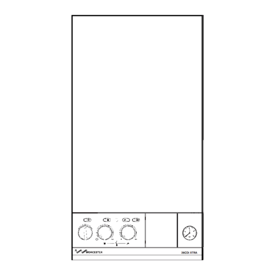
Fig. 25. Duct and Terminal Assembly Fig. 26. Terminal Assembly for Internal for Internal Fitting of the Flue Fitting of the flue Rubber sealing gasket Flue duct Flue terminal Flue terminal ¡ incline Flue duct supplied already Clamping ring assembled to the Air duct flue terminal 10.7 Final Installation... - Page 20 11.1. Appliance and central heating Fig. 27. Appliance Casing, Facia Controls and Location of Equipment. system preperation Remove the cabinet front panel. Check that the electrical supply and the gas service to the appliance are off. See fig 3. Check that all the water connections throughout the system are tight.
- Page 21 Worcester Heat Systems Service Turn off the gas and electricity supplies to the appliance. Department should be contacted. If the appliance does not light, Loosen the burner pressure test point screw and connect a check that it is not in the ‘lockout’...
-
Page 22: Instructions To The User
12.4 Tell the user of the importance of regular servicing. seconds when the appliance will enter a ‘lockout’ state. Carefully Worcester Heat Systems Ltd. offer a comprehensive maintenance open the gas service cock, press the lockout reset button and contract. -
Page 23: Inspection And Servicing
(b) Inner Casing Cover Check the electricity supply to the appliance is turned off. 26CDi Xtra Remove the cabinet front panel. Unscrew the four screws securing the cover to the easing and lift off. See fig. 27. Mains C.H. - Page 24 Unhook the securing rods out of the locating holes in the NOTE: combustion chamber sides. The flame sensing lead is attached to the burner. When the Ease the combustion chamber front and side assembly clear of burner is removed ensure this lead is fed through the inner the appliance.
-
Page 25: Replacement Of Parts
When reassembling ensure the sealing washer located in the IMPORTANT: union nut is replaced. If the washer is damaged it must be The following components are secured to the appliance with replaced. clips, wire clips, screws, union fittings or ‘O’ ring seals to ensure Ensure the sealing grommets are fitted correctly and seal the the joints are sound. - Page 26 2. Air Flow Pressure Switch. See fig.34. 5. Gas to Water Heat Exchanger. See figs. 32 and 33. Check that the electricity supply to the appliance is turned off. Check that the electricity supply to the appliance is turned off. Remove the cabinet front panel and hinge the facia down into Drain the central heating circuit as described in Section 14.2 (a).
- Page 27 Carefully pull off the two electrode leads. Fig. 35. Combustion Chamber Insulation Unscrew the M4 extended nut and remove the spark electrode assembly from the burner and discard. Combustion chamber front and Fit the replacement electrode in the reverse order, check the side assembly spark gap is 3 to 4mm.
- Page 28 12. Central Heating Sensor. See figs. 32 and 33. 14. Circulating Pump. See figs. 37 and 38. Check that the electricity supply to the appliance is turned off. Check that the electricity supply to the appliance is turned off. Remove the inner casing cover as described in Section 13.3 (b). Drain the central heating circuit as described in Section 14.2 (a).
- Page 29 16. Filling Loop. See figs. 37 and 39. Fig. 38. Circulating pump Check that the electricity supply to the appliance is turned off. Drain the central heating circuit as described in Section 14.3 (a). Hinge the facia panel down into the Servicing Position as described in Section 13.3 (c).
- Page 30 18. Water Diverting Valve Micro Switch Assembly. Ease the water diverting valve out of the plastic manifold. See figs. 37 and 40. Remove the securing bracket from the valve and the water filter from the valve cold water inlet. Check that the electricity supply to the appliance is turned off. Retain the plastic manifold, fixing screws, support bracket and Hinge down the facia panel into the Servicing Position as water filter.
- Page 31 Feed the pipe and sealing grommet clear of the inner casing. Carefully pull off all the connectors. Disconnect the mains supply Retain all components and securing clips removed. lead at terminal ST 12 and the earth connection at the back. Pull off the three plastic control knobs.
- Page 32 25. Secondary Heat Exchanger. See figs. 32, 33, 34, 35, 36, 37, 39, and 43. Check that the electricity supply to the appliance is turned off. Drain the central heating circuit as described in Section 14.2 (a). The secondary high efficient heat exchanger is housed in a stainless steel box.
- Page 33 Reassemble the appliance in the reverse order. Ensure all gasket seals and ‘O’ connections are made correctly. Open the valves fill and re-pressurise the system as described in Section 11.1. 26. Condensate Syphon. See fig. 37, 43 and 44. Check that the electricity supply to the appliance is turned off. Hinge down the facia panel into the Servicing Position as described in Section 13.3 (c).
-
Page 34: Short Parts List
Burner Injector – LPG Stereomatic, type 7, 2.7mm dia. 8 716 156 373 0 E04 617 Secondary Heat Exchanger 8 716 121 205 0 Accessories for 26CDi Xtra G.C. No. Part WHS Part No. E04 654 Standard 1M Flue Duct & Terminal... - Page 35 (NG OR LPG) (NG OR LPG)
-
Page 36: Operational Flow Diagrams
16. Operational Flow Diagrams... - Page 38 OVERRUN FUNCTION If heat Run pump demand has until primary occurred in drops to last 30 80°C minutes Within four minutes of last hot water demand primary temperature If heat above 80°C demand has Run fan If primary until primary temperature Run pump for occurred in...
-
Page 39: Fault Finding
17. Fault Finding Note: This fault-finding information is for guidance only. Worcester Heat Systems cannot be held responsible for costs incurred by persons not deemed to be competent. The electronic control system for this boiler incorporates four lights on the facia. These are used to show normal operating status. But as a secondary function, by flashing, they can also be used to help provide fault diagnostics. - Page 40 Is the facia on/off switch turned on? Turn switch on. `(Clockwise) Is there a 230V AC live supply across Check electrical Terminal ST12 pins L supply to boiler. and N Replace control board Has fuse F1 blown? (Section 14.3.23) Replace fuse and investigate cause. Suggestions: Cable damage, connections to (or faults within) pump, fan, external 230V controls, transformer or board.
- Page 41 With CH control knob fully clockwise, does There is no heat Is there 230V AC the boiler ignite and demand. Check room across terminal ST8 appear to run thermostat or mains pins LR and N? normally in central programmer (or link). heating mode? Red diode is Is there a link at...
- Page 42 Drop down the facia. Is the boiler in a very Is the gas valve mode Turn to normal cold environment (less switch in the normal position than 5°C)? position? Replace control board. Boiler is running in (Section 14.3.23) “Autofrost stat” mode. Note: A wet board See Section 17.
- Page 43 Is the gas supply Rectify gas supply connected and at the problem. correct pressure? Remove front panel. Remove inner cover. Repair or replace Reset and restart the Reset and restart the Are the electrodes and electrodes boiler. Can a flame be boiler.
- Page 44 Is the multiway connector at board position ST16 pushed Push fully home. fully home on to the board? Remove multiway connector from board position ST16. Test Is there continuity Repair or replace resistance across from contacts 17 and harness. contacts 17 and 18 18 to DHW sensor? (yellow wires).
- Page 45 Turn off boiler. Is there Does the fan run Remove the fan continuity across the before the fault connector from board C and NO terminals of occurs? position ST1 and the air pressure switch restart the boiler. Is (where green wires are Replace control board.
- Page 46 Light indication during fault not Control board is likely covered by above to be wet or damaged details. or malfunctioning. Check for wet board or connections. Dry and re-use or replace control board. (Section 14.3.23). Hot water sensor Hot water could be off or poorly temperature always fixed to pipe.
- Page 48 Bosch Group Worcester Heat Systems Limited, Cotswold Way, Warndon, Worcester WR4 9SW. Telephone: (01905) 754624. Fax: (01905) 754619. Technical Helpline (0990) 266241 This booklet is accurate at the date of printing but will be superseded and should be disregarded if specifications and/or appearances are changed in the interests of continued improvement.