Carrier 30HXC Installation, Operation And Maintenance Instructions
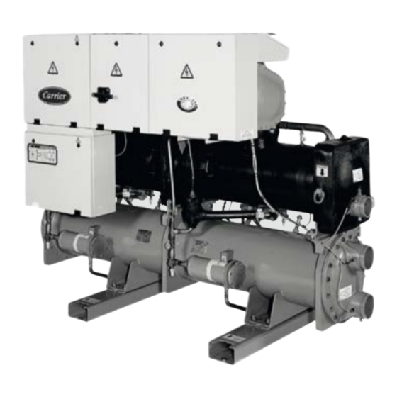
Screw compressor water-cooled liquid chillers
Hide thumbs
Also See for 30HXC:

Related Manuals for Carrier 30HXC


Summary of Contents for Carrier 30HXC
- Page 1 M A I N T E N A N C E I N S T R U C T I O N S Screw Compressor Water-Cooled Liquid Chillers 30HXC 080-375 Nominal cooling capacity 30HXC: 286-1300 kW 50 Hz / 60Hz Original instructions...
-
Page 2: Table Of Contents
5.2 - Electrical data - 30HXC + option 60 ............................ 18 5.3 - Electrical data - 30HXC + option 60 with high condensing temperature (options 150/150A) ........19 5.4 - Physical data - 30HXC + option 61 (380V-3ph-60Hz) ....................... 20 5.5 - Electrical data - 30HXC + option 61 ............................ - Page 3 11 - MAIN OPTIONS AND ACCESSORIES ........................... 41 11.1 - Compressor suction valves (option 92) ..........................42 11.2 - Electric protection level of the 30HXC control boxes to IP44C (option 20) ............... 42 11.3 - Tropicalised control box for 30HXC units (option 22) ..................... 42 11.4 - Disassembled 30HXC units (option 51) ..........................
-
Page 4: Introduction
If this is not the case, there is a risk of material deterioration and injuries to personnel. Prior to the initial start-up of the 30HXC units, the people involved in the on-site installation, start-up, operation and maintenance of Never cover any protection devices. -
Page 5: Equipment And Components Under Pressure
The fluid may then be decomposed into toxic residues when subjected to the Carrier recommends the following drafting for a logbook (the flame: table below should not be considered as reference and does not Stay away from the unit •... - Page 6 CAUTION: Consult Carrier Service for this type of test. Carrier mentions here only the principle of a test without removing the pressure switch: Any handling of refrigerant contained in this product must Verify and and record the setpoints of pressure comply with the F-Gas Directive N°...
-
Page 7: Repair Safety Considerations
1.4 - Repair safety considerations The necessary protection equipment must be available, and appropriate fire extinguishers for the system and the refrigerant type used must be within easy reach. It is compulsory to wear personal protection equipment. The insulation must be removed and warming up must be limited Do not siphon refrigerant. -
Page 8: Preliminary Checks
2 - PRELIMINARY CHECKS ATTENTION: No part of the unit must be used as a walk-way, rack or support. Periodically check and repair or if necessary 2.1 - Check equipment received replace any component or piping that shows signs of damage. The refrigerant lines can break under the weight and release Inspect the unit for damage or missing parts. -
Page 9: Moving And Siting The Unit
2.2 - Moving and siting the unit 2.2.3 - Checks before system start-up Before the start-up of the refrigeration system, the complete 2.2.1 - Moving installation, including the refrigeration system must be verified See chapter 1.1 “Installation safety considerations”. against the installation drawings, dimensional drawings, system piping and instrumentation diagrams and the wiring diagrams. -
Page 10: Dimensions, Clearances, Weight Distribution
3 - DIMENSIONS, CLEARANCES, WEIGHT DISTRIBUTION 3.1 - 30HXC 080-190 30HXC-080 30HXC-090 30HXC-100 30HXC-110 Legend 30HXC All dimensions are in mm. 080-090-100 2558 1800 2200 1000 Evaporator 2565 1850 2200 1000 120-130-140-155 3275 1816 2990 1000 Condenser 3275 1940 2990 1000 175-190 Clearances required for operation and maintenance NOTE: Refer to the certified dimensional drawings supplied with the unit, when designing an installation. -
Page 11: 30Hxc 200-375
3.2 - 30HXC 200-375 30HXC Legend All dimensions are in mm. 3903 1015 1980 3600 1000 230-260-285 3924 1015 2060 3600 1000 Evaporator 4533 1015 2112 4200 1000 310-345-375 Condenser NOTE: Refer to the certified dimensional drawings supplied with the unit, when designing an installation. -
Page 12: Multiple Chiller Installation
3.3 - Multiple chiller installation NOTE: If the walls are higher than 2 m, contact the factory. 1525 1525 Legend Wall Units Notes Unit must have clearances for air flow as follows: Top: do not restrict in any way In case of multiple chillers (up to four units), the respective clearance between them should be increased from 1830 to 2000 mm for the side space requirement. If necessary, add the required clearances for evaporator tube removal. -
Page 13: Physical And Electrical Data - Standard 50Hz Application
4 - PHYSICAL AND ELECTRICAL DATA - STANDARD 50HZ APPLICATION 4.1 - Physical data 30HXC 30HXC Sound levels - standard unit Sound power level dB(A) Sound pressure level at 1 m dB(A) Operating weight 2274 2279 2302 2343 2615 2617 2702 2712 3083 3179 3873 4602 4656 4776... -
Page 14: Electrical Data 30Hxc
4.2 - Electrical data 30HXC 30HXC Power circuit Nominal power supply (Un)* V-ph-Hz 400-3-50 Voltage range 360-440 Control circuit supply The control circuit is supplied via the factory-installed transformer Nominal power input* Nominal current drawn* Max. power input** Circuit A Circuit B 0.88 0.88 0.88 0.88... -
Page 15: Compressor Electrical Data 30Hxc
LRA - Locked rotor current with across-the-line start (A) LRA (Y) - Locked rotor current at reduced current (star/delta start-up mode) (A) LRA (S) 1 cp. - Start-up with reduced current (A) with electronic starter (start-up duration 3 seconds max.) for one compressor per circuit LRA (S) 2 cp. - Start-up with reduced current (A) with electronic starter (start-up duration 3 seconds max.) for two compressors per circuit 4.4 - Electrical data for 30HXC units with high condensing temperatures (option 150/150A) 30HXC Power circuit Nominal power supply (Un)* V-ph-Hz 400-3-50 Voltage range 360-440 Control circuit supply The control circuit is supplied via the factory-installed transformer Max. -
Page 16: Compressor Electrical Data 30Hxc + Option 150/150A
The 30HXC 080-375 units for high condensing temperatures are Technical information directly derived from the standard models. Their application All information is identical to that of the standard 30HXC units, range is the same as that of the standard units, but permits except for the following paragraphs. -
Page 17: Physical And Electrical Data - Optional 60Hz Application (Option 60/61)
5 - PHYSICAL AND ELECTRICAL DATA - OPTIONAL 60HZ APPLICATION (OPTION 60/61) 5.1 - Physical data - 30HXC + option 60 (460V-3ph-60Hz) 30HXC Operating weight* 2274 2279 2302 2343 2615 2617 2702 2712 3083 3179 3873 4602 4656 4776 5477 5553 5721... -
Page 18: Electrical Data - 30Hxc + Option 60
5.2 - Electrical data - 30HXC + option 60 30HXC Power circuit Nominal power supply (Un)* V-ph-Hz 460-3-60 Voltage range 414-506 Control circuit supply The control circuit is supplied via the factory-installed transformer Nominal operating power input* Nominal operating current drawn* Total harmonic distortion*** Max. -
Page 19: Electrical Data - 30Hxc + Option 60 With High Condensing Temperature (Options 150/150A)
5.3 - Electrical data - 30HXC + option 60 with high condensing temperature (options 150/150A) 30HXC Power circuit Nominal power supply (Un)* V-ph-Hz 460-3-60 Voltage range 414-506 Control circuit supply The control circuit is supplied via the factory-installed transformer Max. operationg power input*... -
Page 20: Physical Data - 30Hxc + Option 61 (380V-3Ph-60Hz)
5.4 - Physical data - 30HXC + option 61 (380V-3ph-60Hz) 30HXC Operating weight* 2274 2279 2302 2343 2615 2617 2702 2712 3083 3179 3873 4602 4656 4776 5477 5553 5721 HFC-134a Refrigerant charge* Circuit A Circuit B Polyolester oil CARRIER SPEC. PP 47-32 Circuit A... -
Page 21: Electrical Data - 30Hxc + Option 61
5.5 - Electrical data - 30HXC + option 61 30HXC Power circuit Nominal power supply (Un)* V-ph-Hz 380-3-60 Voltage range 342-418 Control circuit supply The control circuit is supplied via the factory-installed transformer Nominal operating power input* Nominal operating current drawn* Total harmonic distortion*** Max. -
Page 22: Electrical Data - 30Hxc + Option 61 With High Condensing Temperature (Options 150/150A)
5.6 - Electrical data - 30HXC + option 61 with high condensing temperature (options 150/150A) 30HXC Power circuit Nominal power supply (Un)* V-ph-Hz 380-3-60 Voltage range 342-418 Control circuit supply The control circuit is supplied via the factory-installed transformer Max. operationg power input*... -
Page 23: Compressor Electrical Data - 30Hxc + Option 60/61 + Option 150/150A
- Locked rotor current at reduced current (star/delta start-up mode) LRA (S) 1 cp. - Start-up with reduced current with electronic starter (start-up duration 3 seconds max.) for one compressor per circuit LRA (S) 2 cp. - Start-up with reduced current with electronic starter (start-up duration 3 seconds max.) for two compressors per circuit 6 - UNIT CHARACTERISTICS FOR 30HXC UNITS WITH VERY LOW TEMPERATURE OPTION (OPTION 6) 6.2 - Operating range, 30HXC units with very low The 30HXC units with the very low temperature option are temperature option directly derived from the 30HXC models equipped with the high condensing temperature option (option 150). -
Page 24: Evaporator Water Flow (L/S) For 35% Ethylene Glycol
1. Evaporator ∆T = 4 K max. - condenser ∆T = 5 K 2. Operating range applicable for full and reduced load 3. At full load with a condenser entering water temperature below 20°C, a three-way valve must be used to maintain the correct condensing temperature. Legend Unit operating with a condensing pressure control with an analogue water control valve. For transient operating modes (start-up and part load), the unit can operate down to a condenser water temperature of 13°C. Operation permitted, but performances is not optimized 6.3 - Evaporator water flow (l/s) for 35% ethylene glycol Evaporator water flow (l/s) for 30% propylene glycol 30HXC Min.* (closed loop) Max.** 30HXC Min.* (closed loop) Max.** 15.7 11.1 15.7 10.6... -
Page 25: Evaporator Pressure Drop Curve, Units For Very Low Temperature
6.4 - Evaporator pressure drop curve, units for very low temperature The evaporator is equipped with heat insulation of 38 mm thick polyurethane foam. Cooler pressure drop, 30HXC low-brine version 1000 0,01 Pure water flow rate, l/s... -
Page 26: Application Data
°C 6.8* mixture leaving the evaporator must never be less than 2.8 K Evaporator leaving water temperature °C lower than the chilled water entering temperature. Condenser (water-cooled) 30HXC Minimum Maximum Condenser entering water temperature °C 20*** Condenser leaving water temperature °C... -
Page 27: Variable Flow Evaporator
7.4 - Variable flow evaporator 7.6 - Cooler flow rate (l/s) Variable evaporator flow can be used in standard 30HXC chillers. 30HXC Min.* (closed loop) Max.** 080-090 20.8 The chillers maintain a constant leaving water temperature under 25.9 all flow conditions. For this to happen, the minimum flow rate 29.6... -
Page 28: Evaporator Pressure Drop Curve
7.8 - Evaporator pressure drop curve Legend 30HXC 080-090 30HXC 100 30HXC 110 30HXC 120-130 30HXC 140-155 30HXC 175-190 30HXC 200 30HXC 230 30HXC 260-285 10 30HXC 310 11 30HXC 345-375 Water flow rate, l/s 7.9 - Condenser pressure drop curve 1000 Water flow rate, l/s Legend Note: The dotted part of the curves corresponds to the flow values only permitted for 30HXC 080-090-100-110 30HXC 120-130 closed circuits. -
Page 29: Electrical Connection
307.5 1841 307.5 12.5 NOTES: The 30HXC 080-190 units have only one power connection point located at the main disconnect switch. Before connecting electric power cables, it is imperative to check the correct order of the 3 phases (L1 - L2 - L3). -
Page 30: Power Supply
Carrier warranty. If the phase imbalance exceeds 2% for voltage, or 10% for current, contact your local AB = 406 V; BC = 399 V; AC = 394 V electricity supply at once and ensure that the chiller is not switched on until corrective measures have been taken. -
Page 31: Recommended Wire Sections
Refer to the 30GX/HXC Pro-Dialog Plus Controls IOM and the certified wiring diagram supplied with the unit for the field control For the design of 30HXC units installed inside the building, the wirting of the following features: Evaporator pump interlock (mandatory) following standardized installation methods are used, in •... - Page 32 8.4.2 - Selection table of minimum and maximum wire sections - 400 V-3 ph-50 Hz 30HXC Minimum wire Wire type L (m) Maximum wire Wire type L (m) section (mm2)* section (mm2)* 1 x 50 XLPE Cu 1 x 120 XLPE Al...
- Page 33 8.4.4 - Selection table of minimum and maximum wire sections 460V-3ph-60Hz (option 60) 30HXC Minimum wire Wire type L (m) Maximum wire Wire type L (m) section (mm2)* section (mm2)* 1 x 35 XLPE Cu 1 x 120 PVC Al 1 x 35...
- Page 34 8.4.5 - Selection table of minimum and maximum wire sections 460V-3ph-60Hz + option 150/150A 30HXC Minimum wire Wire type L (m) Maximum wire Wire type L (m) section (mm2)* section (mm2)* 1 x 50 XLPE Cu 1 x 150 XLPE Al 1 x 70...
- Page 35 8.4.7 - Selection table of minimum and maximum wire sections 380V-3ph-60Hz + option 150/150A 30HXC Minimum wire Wire type L (m) Maximum wire Wire type L (m) section (mm2)* section (mm2)* 1 x 70 XLPE Cu 1 x 185 XLPE Al 1 x 95 XLPE Cu 1 x 240...
-
Page 36: Water Connections
Control valve Thermostat sleeve Air vent Drain In case additives or other fluids than those recommended by Carrier Flow switch for the evaporator Buffer tank are used, ensure that the fluids are not considered as a gas, and that Flexible connection 10 Filter (mesh size: 1.2 mm = 20 mesh) -
Page 37: Flow Control
Release for 5 seconds Stored information feedback: The light is on for the number of seconds connected. that corresponds to the setpoint. Failure to follow this instruction will void the Carrier guarantee. Internal control: The flow switch goes out for 5 seconds and can then The flow switch is supplied, installed on the evaporator entering be disconnected from the push button. water pipe and preset at the factory to cut out when there is insufficient water flow. -
Page 38: Evaporator And Condenser For The 30Hxc Water Box Bolt Tightening
The water flow in the evaporator should preferably be stopped after unit shut down. If this is not possible, then the flow must be 9.4 - Evaporator and condenser for the 30HXC water maintained in the condenser too. box bolt tightening... -
Page 39: Major System Components And Operation Data
The 06N screw compressor is approved for use with the following lubricant: Carrier material spec PP 47-32. 30HXC chiller use a vessel that is a combination condenser and oil separator. It is mounted below the cooler. Discharge gas leaves the compressor and flows through an external muffler to the oil 10.1.4 - Oil supply solenoid valve... -
Page 40: Electronic Expansion Device (Exv)
10.4 - Economizer transducers to control and regulate system operation (see 30GX/ HXC - Pro-Dialog Plus Control IOM for a more detailed Economizers are installed on 30HXC 190, 285 and 375. explanation). The economizer improves both the chiller capacity and efficiency as well as providing motor cooling. -
Page 41: Main Options And Accessories
11 - MAIN OPTIONS AND ACCESSORIES Options N° Description Advantages 30HXC Low-temperature brine solution Low temperature glycol solution production Covers specific applications such as ice storage 090, 110, 130, 155, 175, down to -10 °C with ethylene glycol and industrial processes 200, 230, 260, 310, 345 IP44C electrical protection level Control box thightness reinforced Permits unit installation in more severe 080-375 envrionments... -
Page 42: Compressor Suction Valves (Option 92)
• a change in use or change of high-pressure refrigerant, or 11.3 - Tropicalised control box for 30HXC units (option 22) after a shut down of more than two years. Components that do not comply, must be changed. Test pressures above the The control boxes are leak-tight and equipped with heaters. -
Page 43: Indication Of Low Charge On A 30Hxc System
12.4 - Indication of low charge on a 30HXC system 12.5 - Electrical maintenance NOTE : To check for low refrigerant charge on a 30HXC, several When working on the unit comply with all safety precautions factors must be considered. A flashing liquid-line sightglass is decribed in section “Maintenance safety considerations”. -
Page 44: Integral Oil Filter Change
The switch that has been selected for detecting reverse rotation is Carrier part number HK01CB001. It is available as part of the “Compressor installation package” (part No. 06NA 660 013). -
Page 45: Corrosion Control
(can be heard if surroundings are relatively quiet). The actuator should knock when it reaches the bottom of its stroke. If it is believed that the valve is not working properly, contact your Carrier service department for further checks on: output signals on EXV module •... -
Page 46: Start-Up Checklist For 30Hxc Liquid Chillers (Use For Job File)
13 - START-UP CHECKLIST FOR 30HXC LIQUID CHILLERS (USE FOR JOB FILE) Preliminary information Job name: ....................................... Location: ........................................ Installing contractor: ..................................... Distributor: ......................................Start-up performed by: ..................................Equipment Model: .................... Serial number ................Compressors Circuit A Circuit B 1. Model number ................1. Model number .............. - Page 47 Check condenser system All condenser water valves are open All condenser piping is connected properly All air has been vented from the system Condenser water pump (CWP) is operating with the correct rotation. Condenser water pump amperage: Rated: .…….. Actual: ……… Unit start-up CWP starter has been properly interlocked with the chiller Oil level is correct...
- Page 48 Check pressure drop across the condenser Entering condenser = ......(kPa) Leaving condenser = ......(kPa) (Leaving - entering) = ......(kPa) WARNING: Plot condenser pressure drop on performance data chart (in product data literature) to determine total litres per second (l/s) and find unit’s minimum flow rate.
- Page 50 Order No: 13050, 05.2016 - Supersedes order No: 13050, 03.2011. Manufacturer: Carrier SCS, Montluel, France. Manufacturer reserves the right to change any product specifications without notice. Printed in the European Union.