Panasonic NN-S262SF Service Manual
Hide thumbs
Also See for NN-S262SF:
- Operating instructions manual (42 pages) ,
- Service manual (92 pages) ,
- Service manual (52 pages)
Table of Contents
Troubleshooting

Related Manuals for Panasonic NN-S262SF


Summary of Contents for Panasonic NN-S262SF
-
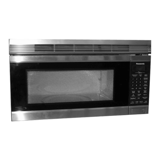
Page 1: Microwave Oven
ORDER NO.SIMMC 0203005C1 Microwave Oven NN-S262SF NN-S262BF NN-S262WF NN-S252BF NN-S252WF APH(USA) CPH(CANADA) © 2002 Shanghai Matsushita Microwave Oven Co., Ltd. All rights reserved. Unauthorized copying and distribution is a violation of law. - Page 2 NN-S262SF / NN-S262BF / NN-S262WF / NN-S252BF / NN-S252WF...
- Page 3 NN-S262SF / NN-S262BF / NN-S262WF / NN-S252BF / NN-S252WF...
-
Page 4: Table Of Contents
NN-S262SF / NN-S262BF / NN-S262WF / NN-S252BF / NN-S252WF CONTENTS Page Page 1 FEATURE CHART 12 PROCEDURE FOR MEASURING MICROWAVE ENERGY 2 CONTROL PANEL (APH) LEAKAGE 3 CONTROL PANEL (CPH) 13 TROUBLESHOOTING GUIDE 4 OPERATION AND DIGITAL PROGRAMMER CIRCUIT TEST... -
Page 5: Feature Chart
NN-S262SF / NN-S262BF / NN-S262WF / NN-S252BF / NN-S252WF 1 FEATURE CHART MODEL NN-S262 NN-S252 FEATURE Five Stage Cooking Inverter Turbo Defrost Sensor Reheat Sensor Cooking Auto Reheat Inverter Auto Cooking Quick Min Popcorn Digital Clock Timer Child Safety Lock... -
Page 6: Control Panel (Cph)
NN-S262SF / NN-S262BF / NN-S262WF / NN-S252BF / NN-S252WF 3 CONTROL PANEL (CPH) -
Page 7: Operation And Digital Programmer Circuit Test Procedure
NN-S262SF / NN-S262BF / NN-S262WF / NN-S252BF / NN-S252WF 4 OPERATION AND DIGITAL PROGRAMMER CIRCUIT TEST PROCEDURE 4.1. To set clock 4.3. Inverter turbo defrost OPERATION SCROLL DISPLAY OPERATION SCROLL DISPLAY 1. Plug the power supply cord BEFORE USE REFER TO 1. -
Page 8: Auto Reheat
NN-S262SF / NN-S262BF / NN-S262WF / NN-S252BF / NN-S252WF 4.6. Auto reheat OPERATION SCROLL DISPLAY 1. Press Auto Reheat twice for two servings. 2. Press Start pad.Auto Reheat cycle begins time counts down. 3.When cooking time has Time of day or colon if set appears elapsed, Oven beeps 5 times and in the display. -
Page 9: Schematic Diagram (Aph)
NN-S262SF / NN-S262BF / NN-S262WF / NN-S252BF / NN-S252WF 5 SCHEMATIC DIAGRAM (APH) -
Page 10: Schematic Diagram (Cph)
NN-S262SF / NN-S262BF / NN-S262WF / NN-S252BF / NN-S252WF 6 SCHEMATIC DIAGRAM (CPH) -
Page 11: Description Of Operating Sequence
NN-S262SF / NN-S262BF / NN-S262WF / NN-S252BF / NN-S252WF 7 DESCRIPTION OF OPERATING SEQUENCE 7.1. Variable power cooking 7.2. Inverter power supply circuit control NEW H.V. High Voltage Inverter Power supply (U) controls output power This Inverter Power Supply Circuit supplies 4,000V DC to the by the signal from Digital Programmer Circuit (DPC). -
Page 12: Cautions To Be Observed When Troubleshooting
NN-S262SF / NN-S262BF / NN-S262WF / NN-S252BF / NN-S252WF 8 CAUTIONS TO BE OBSERVED WHEN TROUBLESHOOTING Unlike many other appliances, the microwave oven is high- 8.3. When parts must be replaced, voltage, high-current equipment. Though it is free from danger remove the power plug from in ordinary use, extreme care should be taken during repair. -
Page 13: Confirm After Repair
NN-S262SF / NN-S262BF / NN-S262WF / NN-S252BF / NN-S252WF 8.5. Avoid inserting nails, wire, etc. 8.6. Confirm after repair through any holes in the unit 1. After repair or replacement of parts, make sure that the during operation. screws of the oven, etc. are neither loose nor missing. -
Page 14: Disassembly And Parts Replacement Procedure
NN-S262SF / NN-S262BF / NN-S262WF / NN-S252BF / NN-S252WF 9 DISASSEMBLY AND PARTS REPLACEMENT PROCEDURE 9.1. Magnetron 1. Discharge the high voltage capacitor. 2. Disconnect 2 connectors from fan motor B. 3. Remove 4 screws holing fan motor B (U) assembly. - Page 15 NN-S262SF / NN-S262BF / NN-S262WF / NN-S252BF / NN-S252WF 8. Release 2 tabs to make Inverter bracket flat, and then 9.3. Low voltage transformer remove orifice. and/or power relays (RY1, 9. Release 2 tabs on the Inverter bracket and make flat.
-
Page 16: Door Assembly
NN-S262SF / NN-S262BF / NN-S262WF / NN-S252BF / NN-S252WF 9.5. Door assembly 9.6. Stirrer motor 1. Remove door C from door E by carefully pulling outward 1. Release 1 canoe clip on the cover and then remove the starting from upper right hand corner using a flat blade cover. -
Page 17: Turntable Motor
NN-S262SF / NN-S262BF / NN-S262WF / NN-S252BF / NN-S252WF 9.9. Fan motor B (for magnetron cooling) 1. Disconnect 2 lead wires from fan motor B terminals. 2. Remove 4 screws holing fan motor B(U)Assembly. 3. Remove 4 screws which holding fan case installation plate on the fan case C. -
Page 18: Component Test Procedure
NN-S262SF / NN-S262BF / NN-S262WF / NN-S252BF / NN-S252WF 10 COMPONENT TEST PROCEDURE 10.3. Magnetron CAUTION NEW. H.V. 1. High voltage is present at the high voltage terminal of the High Voltage Inverter (U) including aluminum heat sink during any cook Continuity checks can only indicate an open filament or a cycle. - Page 19 NN-S262SF / NN-S262BF / NN-S262WF / NN-S252BF / NN-S252WF 10.5. Inverter power supply (U) DO NOT try to REPAIR this H.V. Inverter power supply (U).Replace as whole H.V. Inverter(U) Unit. DANGER HIGH VOLTAGE Test if failure codes of H97 or H98 appears by doing the following procedure.
-
Page 20: Measurements And Adjustments
NN-S262SF / NN-S262BF / NN-S262WF / NN-S252BF / NN-S252WF 11 MEASUREMENTS AND ADJUSTMENTS 11.1. Adjustment of primary latch switch, secondary latch switch and short switch. 1. When mounting Primary latch switch,Secondary latch switch and short switch to door hook assembly, mount the Primary latch switch, the Secondary latch switch and the short switch to the door hook assembly as shown in table. -
Page 21: Procedure For Measuring Microwave Energy Leakage
NN-S262SF / NN-S262BF / NN-S262WF / NN-S252BF / NN-S252WF 12 PROCEDURE FOR MEASURING MICROWAVE ENERGY LEAKAGE 12.2.1. Measurement with the outer panel WARNING Check for radiation leakage after every servicing. Should the leakage removed. be more than 2 mW/cm (1mW/cm for Canada) inform PASC, PSC, or PCI immediately. - Page 22 NN-S262SF / NN-S262BF / NN-S262WF / NN-S252BF / NN-S252WF 12.4. At least once a year, have the radiation monitor checked for calibration by its manufacturer.
-
Page 23: Troubleshooting Guide
NN-S262SF / NN-S262BF / NN-S262WF / NN-S252BF / NN-S252WF 13 TROUBLESHOOTING GUIDE CAUTION 1. Check grounding before checking for trouble. 2. Be careful of high voltage circuit. 3. Discharge high voltage capacitor. 4. When checking the continuity of the switches or the high voltage transformer,disconnect one lead wire from these parts and then check continuity with the AC plug removed. -
Page 24: Trouble Related To Digital Programmer Circuit
NN-S262SF / NN-S262BF / NN-S262WF / NN-S252BF / NN-S252WF SYMPTOM CAUSE CORRECTIONS 13. Oven returns to plugged in mode after 1. Open or loose wiring of sensor terminal from 18 seconds elapses on the Auto sensor cooking mode. 2. Open steam sensor 3. - Page 25 NN-S262SF / NN-S262BF / NN-S262WF / NN-S252BF / NN-S252WF 13.2. Troubleshooting of inverter circuit (U) and magnetron NEW H.V. This oven is programmed with a self diagnostics failure code system which will help for troubleshooting. H97, H98, and H99 are the provided failure codes to indicate magnetron and inverter circuit problem areas.
-
Page 26: How To Check The Semiconductors Using An Ohm Meter
NN-S262SF / NN-S262BF / NN-S262WF / NN-S252BF / NN-S252WF 13.3. How to check the semiconductors using an OHM meter... -
Page 27: Exploded View And Parts List
NN-S262SF / NN-S262BF / NN-S262WF / NN-S252BF / NN-S252WF 14 EXPLODED VIEW AND PARTS LIST... -
Page 28: Parts List
NN-S262SF / NN-S262BF / NN-S262WF / NN-S252BF / NN-S252WF 15 PARTS LIST NOTE: 1. When ordering replacement part(s), please use part number(s) shown in this part list. Do not use description of the part. 2. Important safety notice: Components identified by mark have special characteristics important for safety. - Page 29 NN-S262SF / NN-S262BF / NN-S262WF / NN-S252BF / NN-S252WF Ref. No. Part No. Part Name & Description Pcs/Set Remarks F61455H00AP THERMAL CUTOUT F61455E60XN THERMAL CUTOUT A606Y4T00AP H.V.INVERTER (U) A606Y4T00CP H.V.INVERTER (U) 2M261-M32F MAGNETRON 2M261-M32G MAGNETRON B62308250AP FUSE 18A/125V B62314000AP FUSE HOLDER...
-
Page 30: Door Assembly
NN-S262SF / NN-S262BF / NN-S262WF / NN-S252BF / NN-S252WF 16 DOOR ASSEMBLY Ref. No. Part No. Part Name & Description Pcs/Set Remarks F3018-1200 DOOR KEY A F302A5H00AP DOOR A (U) S262SF F302A5H00BAP DOOR A (U) S262BF, S252BF F302A5H00HAP DOOR A (U) -
Page 31: Escutcheon Base Assembly
NN-S262SF / NN-S262BF / NN-S262WF / NN-S252BF / NN-S252WF 18 ESCUTCHEON BASE ASSEMBLY Ref. No. Part No. Part Name & Description Pcs/Set Remarks F603L5H00AP D.P.CIRCUIT S262SF APH, S262BF/WF APH F603L5H20AP D.P.CIRCUIT S252BF/WF APH F603L5H00CP D.P.CIRCUIT S262SF CPH, S262BF/WF CPH F603L5H20CP D.P.CIRCUIT... -
Page 32: Packing And Accesories
NN-S262SF / NN-S262BF / NN-S262WF / NN-S252BF / NN-S252WF 19 PACKING AND ACCESORIES Ref. No. Part No. Part Name & Description Pcs/Set Remarks F00035H00AP INSTRUCTION MANUAL F00035H00CP INSTRUCTION MANUAL F01025H00AP PACKING CASE PAPER S262SF APH F01025H10BAP PACKING CASE PAPER S262BF APH... -
Page 33: Digital Programmer Circuit
NN-S262SF / NN-S262BF / NN-S262WF / NN-S252BF / NN-S252WF 20 DIGITAL PROGRAMMER CIRCUIT SCHEMATIC DIAGRAM... - Page 34 NN-S262SF / NN-S262BF / NN-S262WF / NN-S252BF / NN-S252WF...
-
Page 35: Digital Programmer Circuit
NN-S262SF / NN-S262BF / NN-S262WF / NN-S252BF / NN-S252WF 21 DIGITAL PROGRAMMER CIRCUIT PARTS LIST Ref. No. Part No. Part Name & Description Pcs/Set Remarks BZ310 AEFBTFM571 BUZZER 2.0KHz C221, C440, C13 AECUU06F103Z CHIP CAPACITOR 0.01µF/50V C582 AECUU06F103Z CHIP CAPACITOR 0.01µF/50V (S262SF/BF/WF) - Page 36 NN-S262SF / NN-S262BF / NN-S262WF / NN-S252BF / NN-S252WF Ref. No. Part No. Part Name & Description Pcs/Set Remarks R571 AERJ06J753R CHIP RESISTOR 75K, 1/16W, 5% (S262SF/BF/WF) R14, R180 AERDY2TJ103T CARBON FILM RESISTOR 10K, 1/4W, 5% R228, R290 AERDY2TJ104T CARBON FILM RESISTOR...