Table of Contents
Troubleshooting

Related Manuals for LG ATNH126ELFB


Summary of Contents for LG ATNH126ELFB
-
Page 1: Air Conditioner
website http://www.lgservice.com e-mail http://www.lgeservice.com/techsup.html Synchro Air Conditioner SERVICE MANUAL CAUTION • BEFORE SERVICING THE UNIT, READ THE SAFETY PRECAUTIONS IN THIS MANUAL. • ONLY FOR AUTHORIZED SERVICE PERSONNEL. -
Page 2: Table Of Contents
Synchro Air Conditioner Service Manual TABLE OF CONTENTS Model Number Nomenclature ..............3 Safety Precautions ..................4 Model Names....................11 External Appearance ..................12 Dimensions ....................13 Product Specifications ................22 Combination table ..................27 Installation....................28 Operation ....................63 Control Devices and Function ..............78 Schematic Diagram ..................91 Piping Diagrams ..................105 Troubleshooting Guide................112 (3-way) Valve ....................133 Exploded View &... -
Page 3: Model Number Nomenclature
Model Number Nomenclature Model Number Nomenclature Indoor Unit Serial Number Function A : Basic E : E/Grille F : Plasma + Elevation grille Panel type Cassette L : Basic panel, W : Wooden panel Duct : L Chassis type Cassette : E/F/D, Convertible : E/B, Duct : H/G/R Electrical Rating 6 : 1Ø... -
Page 4: Model Names
24,000 30,000 36,000 48,000 60,000 Type Name (3.5) (5.3) (7.0) (8.8) (10.6) (14.1) (17.6) ATNH126ELFB ATNH186ELFB Ceiling Cassette 4-Way ATNH246FLFB ATNH306FLFB ATNH366DLFB ATNH486DLFB ATNH606DLFB AVNH126ELAB Ceiling & Floor(Convertible) AVNH186BLAB AVNH246BLAB AVNH306BLAB ABNH186HLAB ABNH246HLAB Ceiling Concealed Duct ABNH306GLAB ABNH366GLAB ABNH486RLAB ABNH606RLAB... -
Page 5: External Appearance
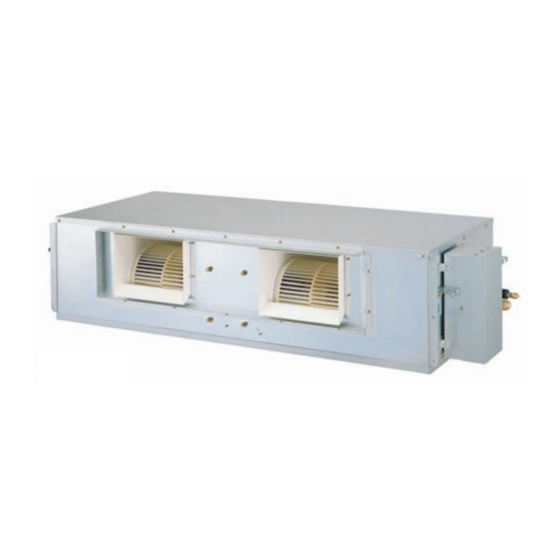
External Appearance External Appearance Indoor Unit Ceiling Cassette-4Way Ceiling & Floor(Convertible) AVNH126ELAB / AVNH186BLAB ATNH126ELFB / ATNH186ELFB AVNH246BLAB / AVNH306BLAB ATNH246FLFB / ATNH306FLFB ATNH366DLFB / ATNH486DLFB ATNH606DLFB Ceiling Concealed Duct ABNH186HLAB / ABNH246BHLAB ABNH306GLAB / ABNH366BGLAB ABNH486RLAB / ABNH606RLAB Outdoor Unit... -
Page 6: Dimensions
Dimensions Dimensions Indoor Unit 1. Cassette Type - TE(12K/18K) 600 (Ceiling opening) 39.5 521(Hanging bolt) 39.5 570 Unit size Unit:mm CLOSE OPEN OPEN CLOSE (unit : mm) Number Name Descripition Liquid pipe connection ø6.35 flare Gas pipe connection 12k: ø9.52, 18k: ø12.7 flare Drain pipe connection Power supply connection Air discharge grill... - Page 7 Dimensions 2. Cassette Type - TF (24K/30K) 790 (Ceiling opening) 572(Hanging bolt) 744 Unit size Unit:mm (unit : mm) Number Name Descripition Liquid pipe connection ø6.35 flare Gas pipe connection 24K: ø12.7, 30K: ø15.88 flare Drain pipe connection Power supply connection Air discharge grill Air suction grill 14 Synchro Air Conditioner...
- Page 8 Dimensions 3. Cassette Type - TD(36K/48K/60K) 875 (Ceiling opening) 785 (Hanging bolt) 840 Unit size Unit:mm Fresh Air Inlet (unit : mm) Number Name Descripition Liquid pipe connection 36K: ø6.35, 48K/60K: ø9.52 flare Gas pipe connection 36K: ø15.88, 48K/60K: ø19.05 flare Drain pipe connection Power supply connection Air discharge grill...
- Page 9 Dimensions 4. Ceiling & Floor(Convertible) - VB(18K/24K), VE(12K) 1 2 0 0 Ø10 Stud Bolt hole (Rear Side) (Installation Plate) (Unit: mm) Note: 1. Pipe Specification(mm) Model Liquid 18k, 24k Ø 6.35 Ø 12.7 More than Ø 6.35 Ø 15.88 More than 20cm 20cm...
- Page 10 Dimensions 5. Ceiling Concealed Duct - BH(18K/24K), BG(30K/36K), BR(48K/60K) Note: 1. Pipe Specification(mm) Model Liquid 18, 24k Ø 12.7 Ø 6.35 Ø 15.88 30, 36 48, 60k Ø 9.52 Ø 19.05 (Unit: mm) Capacity ABNH186HLAB 932 882 355 45.5 450 163 260 61.5 243 212.3 243 110 130 30 158.5 ABNH246HLAB...
- Page 11 Dimensions Outdoor Unit AUUW48/6060 500(bolt hole) Air outlet inlet inlet Service Panel Knockout hole (For the control wiring, the power supply, refrigerant connecting pipe) Knockout hole (For the control wiring, the power supply, (Unit : mm) refrigerant connecting pipe) 18 Synchro Air Conditioner...
- Page 12 Dimensions 4-hole for anchor bolts AUUH488B Control cover Liquid side 3-way valve Gas side 3-way valve Model AUUH488B Dimensions 1,165 1,135 Ø9.52 Ø19.05 Service Manual 19...
- Page 13 Dimensions AUUH7280 500(bolt hole) Air outlet inlet inlet Service Panel Knockout hole (For the control wiring, the power supply, refrigerant connecting pipe) Knockout hole (For the control wiring, the power supply, (Unit : mm) refrigerant connecting pipe) 20 Synchro Air Conditioner...
- Page 14 Dimensions AUUH10080 1280 900(bolt hole) Air outlet inlet inlet Service Panel Knockout hole (For the control wiring, the power supply, refrigerant connecting pipe) Knockout hole (For the control wiring, the power supply, refrigerant connecting pipe) Service Manual 21...
-
Page 15: Product Specifications
Product Specifications Product Specifications Indoor Unit Ceiling Cassette - 4way Indoor Unit Type Model Indoor unit ATNH126ELFB ATNH186ELFB ATNH246FLFB ATNH306FLFB PT-HEC(F) PT-HEC(F) PT-HFC(F) PT-HFC(F) Decoration panel Rated Cooling Capacity kcal/hr(W) 3024(3517) 4536(5275) 6048(7033) 7056(8205) Btu/hr 12000 18000 24000 28000 Ratedl Heating Capacity... - Page 16 Product Specifications Ceiling Concealed Duct - High Static Indoor Unit Type ABNH186HLAB ABNH246HLAB ABNH306GLAB Model Rated Cooling Capacity kcal/hr(W) 4536(5275) 6048(7034) 7560(8791) Btu/hr 18000 24000 30000 Ratedl Heating Capacity kcal/hr(W) 5116(5949) 6955(8089) 8694(10110) Btu/hr 20300 27600 34500 Air Circulation Indoor(H/M/L) CMM(CFM) 16.5/14.5/13(583/512/459) 18/16.5/14(636/583/494)
- Page 17 Product Specifications Ceiling & Floor (Convertible) Indoor Unit Type AVNH126ELAB AVNH186BLAB AVNH246BLAB AVNH306BLAB Model Rated Cooling Capacity kcal/hr(W) 3024(3517) 4536(5274) 6048(7032) 6653(7377) Btu/hr 12000 18000 24000 26400 Ratedl Heating Capacity kcal/hr(W) 3478(4044) 5116(5949) 6955(8089) 7635(8880) Btu/hr 13800 20300 27600 30300 Air Circulation Indoor(H/M/L) CMM(CFM)
- Page 18 Product Specifications Outdoor Unit AUUW4860 AUUW6060 Model Cooling Capacity kcal/hr(W) 10600~12100(12300~14000) 12100~13600(14000~15800) Btu/hr 42000~48000 48000~56000 Heating Capacity kcal/hr(W) 12200~13900(14200~16200) 12200~16200(16200~18900) Btu/hr 48300~55200 55200~64400 Input Cooling/Heating 1900~5940/1920~6100 2080~7000/2250~7930 Running Current Cooling/Heating 8.5~26.6/8.6~27.3 9.3~31.3/10.1~35.5 Starting Current Cooling/Heating Power Supply Ø,V,Hz 1,220~240,50 1,220~240,50 Power Factor 90 ~ 97 90 ~ 97...
- Page 19 Product Specifications Model AUUH488B AUUH7280 AUUH10080 Cooling Capacity kcal/hr(W) 12096(14607) 18144(21101) 24192(28135) Btu/hr 48000 72000 96000 Heating Capacity kcal/hr(W) 13305(15474) 19958(23211) 27820(32355) Btu/hr 52800 79200 110400 Input Cooling/Heating 5300 / 5050 8000 / 7700 11100 / 11000 Running Current Cooling/Heating 10.0 / 9.5 14.7 / 14.4 20 / 19.7...
-
Page 20: Combination Table
Combination table Combination table MPS Inverter AUUW4860 AUUW6060 Synchro Combination(k Btu/h) Total(k Btu/h) Branch Kit Synchro Combination(k Btu/h) Total(k Btu/h) Branch Kit 18 + 24 (2:3) PMUB23A 24 + 30 (2:3) PMUB23A Duo(2 Unit) 24 + 24 (1:1) PMUB11A Duo(2 Unit) 30 + 30 (1:1) PMUB11A 24 + 30 (2:3) -
Page 21: Installation
Installation Piping length and the elevation Install the branch pipe so that pipe length and difference between high and low will not exceed below SPEC. Branch Outdoor Unit Indoor Unit Main (L1) AUUH488B AUUW4860/AUUW6060/AUUH7280 Branch Main (L1) AUUH10080 Pipe Length(m) Spec. -
Page 22: Piping Connection
Installation Piping Connection 1. Form the piping according to its routing. Avoid bending and bending back the same piping point more than three times. (This will result in hardening the pipe.) 2. After deforming the piping, align centers of the union fitting of the indoor unit and the piping, and tighten them firmly with wrenches. - Page 23 Installation Refrigerant Additional Charging Method 1. AUUH488B/AUUW4860/AUUW6060 There is not additional charging of refrigerant by main pipe of 30m below. For additional charging method, see below table. Model Synchro Refrigerant Additional charging (kg) Refrigerant = (L1-30) x A + (L2+L3-20) x 0.03 AUUH488B 0.07 Trio...
- Page 24 Installation Branch Kit 1. Type of branch pipe Separately use a branch pipe depending on indoor capacity for installation. Unbalance type of branch pipe must be connected depending on large capacity or small capacity. Indoor Classification Model Name Capacity Ratio(%) Remark 2 UNIT PMUB11A...
- Page 25 Installation 4 .Thermal insulation work • Securely wrap the refrigerant and the branch pipe by using thermal insulation materials provided. When using thermal insulation materials released, use withstand heat insulation materials (thickness of more than 15mm). • Securely adhere thermal insulation materials wrapping the branch pipe so that they do not widen.
-
Page 26: Wiring Connection
Installation Wiring Connection 1. All wiring must comply with LOCAL REGULATIONS. 2. Select a power source that is capable of supplying the current as required by the air conditioner. 3. Feed the power source to the unit via a distribution switch board designed for this purpose. 4. - Page 27 Installation Auto addressing Auto addressing work should be done for simultaneous operation. Addressing work assigns address to each Indoor Unit. When firstly installing product or replacing the Indoor Unit PCB. AUUW4860/AUUW6060 2. Operation method of pipe length s/w Main PCB Convert the s/w toward "long pipe"...
- Page 28 Installation How to simultaneous operating - Keep the following procedure when simultaneously operating two units or more cassette type, duct type, and convertible type of indoor units via the free joint. 1. Turn on the power of the unit by the installed remote controller, a wire or a wireless remote controller.
-
Page 29: Test Running
Installation Test running 1. PRECAUTIONS IN TEST RUNNING • The initial power supply must provide at least 90% of the rated voltage. Otherwise, the air conditioner should not be operated. CAUTION For test run, carry out the cooling operation firstly even during heating season. If heating operation is carried out firstly, it leads to the trouble of compressor. -
Page 30: Operation
Operation Operation Function of control 1. MAIN UNIT FUNCTION • DISPLAY Operation Indicator • On while in appliance operation, off while in appliance pause • Flashing while in disconnection or short in Thermistor (3 sec off / 0.5 sec on) Sleep Timer Indicator •... - Page 31 Operation • While compressor on, the indoor fan is off when the indoor pipe temp. is below 20°C, when above 27°C , it operates with the low or setting speed. When the indoor pipe temp is between 20°C and 27°C, it operates with Super-Low(while in sleep mode, with the medium airflow speed).
- Page 32 Operation 2) Fuzzy Operation for Dehumidification • According to the setting temperature selected by Fuzzy rule, when the intake air temp is 0.5°C or more below the setting temp, the compressor is turned off. When 0.5°C or more above the setting temp, the com- pressor is turned on.
-
Page 33: Sleep Timer Operation
Operation I Off-Timer <=> On-Timer Operation • When the set time is reached after the on/off time is input by the remote control, the on/off-timer operation is carried out according to the set time. I Sleep Timer Operation • When the sleep time is reached after <1,2,3,4,5,6,7,0(cancel) hr> is input by the remote control while in appliance operation, the operation of the appliance stops. -
Page 34: Forced Operation
Operation I Forced Operation • To operate the appliance by force in case that the remote control is lost, the forced operation selection switch is on the main unit of the appliance to operate the appliance in the standard conditions. •... - Page 35 Operation CST Type Operation ON/OFF Operation Mode Selection Cooling Operation Mode ( Soft Dry Operation Mode ( Heating Operation Mode ( Auto Operation Mode ( (Cooling (Heating model only) model only) Fan Speed Selection AUTO (Low) (Med) (High) Room Temperature Display : High:39°C ↔...
-
Page 36: Duct Type
Operation Duct Type Operation ON/OFF Operation Mode Selection Cooling Operation Mode ( Soft Dry Operation Mode ( Heating Operation Mode ( Auto Operation Mode ( (Cooling (Heating model only) model only) Fan Speed Selection (Low) (Med) (High) Room Temperature Display : High:39°C ↔... - Page 37 Operation Convertible Operation ON/OFF Operation Mode Selection Cooling Operation Mode.( Auto Operation Mode.( (Cooling (Heating Healthy Dehumidification Operation Mode.( Heating Operation Mode.( model only) model only) Fan Speed Selection (Low) (Med) (High) (CHAOS) Room, Temperature Checking : (High:39°C Low:11°C) Temperature Setting HIGH TEMPERATURE Down to 18°C...
-
Page 38: Remote Control Operation
Operation Remote Control Operation Convertible Type Remote controller The Remote Controller transmits the signals to the system. 1. START/STOP BUTTON Signal transmitter Operation starts when this button is pressed and stops when the button is pressed again. 2. OPERATION MODE SELECTION BUTTON Used to select the operation mode. - Page 39 Operation CST Type Remote controller AUTO SWING OPERATION SET TEMP FAN SPEED SUB FUNCTION Room Temp Heat Pump Model AUTO Heater Preheat Defrost Humidify Filter Out door Time ZONE 1 2 3 4 Timer Operation unit Program set Set no. Time Cooling Model Timer Cancel...
- Page 40 Operation Duct Type Remote Controller AUTO SWING OPERATION SET TEMP FAN SPEED SUB FUNCTION Room Temp AUTO Heater Preheat Defrost Humidify Filter Out door 1 2 3 4 Time ZONE Timer Operation unit Program set Set no. Time Signal Receiver Timer Cancel Program...
-
Page 41: Two Thermistor System
Operation 1. Two Thermistor System (1) Open the rear cover of the wired remote-controller to set the mode. (2) Select one of three selectable modes as follows. • Position 1: The room temperature is controlled by the thermistor of the main body. •... - Page 42 Operation 3. E.S.P.(External Static Pressure) Setting (Duct type) (1) Open the rear cover of the wired remote-controller to set the mode. (2) Select one of three selectable modes as follows. I Without Zone System 1. Position V-H, F-H: • This position sets the maximum E.S.P as a default set. 2.
- Page 43 Operation 4. How to Set E.S.P? Procedure of RPM change: Ex) External Static pressure is 6mmAq for 36k. • To protect the unit, compressor is designed to be off during E.S.P. setting. Push the "On/Off" button. The unit will start. AUTO SWING OPERATION SET TEMP...
- Page 44 Operation [Table. 1] Static Pressure(mmAq) Model Name Step CMM(CFM) Setting Value High 16.5(583) 14.5(512) 13(459) High 18(636) 16.5(583) 14(494) High 26.5(936) 23(812) 20(706) High 32(1130) 29(1024) 26.5(936) High 40(1412) 35(1235) 30(1059) High 50(1766) 45(1589) 40(1423) : 1. Be sure to set the value refering table 1. Unexpected set value will cause mal- Note function.
-
Page 45: Control Devices And Function
Control Devices and Function Control Devices and Function Simple Central Control Features • Easy operation button. • Independent operation for 16 indoor units each. • Simultaneous turn ON/OFF for all of indoor units connected. • Easy change operation mode to cooling or heating •... -
Page 46: Electrical Wiring
Control Devices and Function Electrical wiring I PICTORIAL VIEW OF THE CONNECTION Outdoor unit Outdoor unit PI485 : PNF-P14A0M MAIN PCB PI485 MAIN PCB Control Box CN_CENTRAL MAIN PCB CN_CENTRAL PI485 CENTRAL CONTROL CN OUT UNIT • Special purchase: Central control, PI485(PNF-P14A0M) I ONE SIMPLE CENTRAL CONTROL CONNECTION INDOOR UNIT INDOOR UNIT 1... - Page 47 * LGAP : LG Air conditioners Protocol • Function of LG Network - It is possible to connect the network of LG air conditioners and to connect various contents of the network system, which is simple, deluxe and PC central control.
- Page 48 Control Devices and Function Indoor Unit Address setting Method 1. Press 13(program) and 16(set and clear) key more Using Wired Remocon than 3 second then "Address Setting Mode" starts. 2. Set the address of indoor unit by using "Temperature setting" key. I Range of address : 00 ~ FF AUTO SWING OPERATION...
-
Page 49: Test Run Method
Control Devices and Function Test run method 1. Set the wiring of system and indoor unit. 2. Apply power to the setting. 3. Do auto addressing to the outdoor unit. 4. After addressing, initialize the central controller(Manual initialize: Total on + total off + 16 key). •... - Page 50 Control Devices and Function I INSTALLATION ORDER Remove upper & lower case. Fixate screw in the holes of the For Dip switch, and Rotary case bottom. switch setting, refer to the page “How to Install”. For wiring connection, refer page Adjust the upper case in accor- Check the operation by supply- “Installation Procedure”...
-
Page 51: Rotary Switch
Control Devices and Function I. ROTARY SWITCH SETTING(INSTALLATION FOR 2 OR MORE SIMPLE CENTRAL CONTROL) The setting of Group Number in the Central Control is done by the rotary switch as shown in the figure below. It is possible to set 0~15 Group(Total 16 Groups). All the numbers on the rotary switch represent the different Group Numbers. -
Page 52: Deluxe Central Control
Control Devices and Function Deluxe Central Control 2.1.1 Summary Deluxe Central control is a product available for individual and integrated monitoring and control of maximum 256 of TPS Inverter Multi air conditioner systems. Specially, operation status of the individual air conditioner can be particularly checked. - Page 53 Control Devices and Function Major Characteristics Figure 2) Deluxe Central control 1. Individual/Integrated Operation/Monitoring I You can identify operation status of the air conditioner, operation mode, wind quantity, wind direction, lock- ing, temperature setting and error, etc by selecting the installed air conditioner through individual selection, group selection or all selection.
- Page 54 Control Devices and Function 6. Convenient GUI / Touch Screen I Not requires special education for using the Deluxe Central control, conveniently used only by pressing the buttons on the screen, and its function can be understood with intuitive pictogram. Especially schedule setting is done by simply by dragging, different from the existing system requiring to press the button by more than average 30 times to enter a schedule.
- Page 55 Control Devices and Function Figure 3) Deluxe Central control Table 1) Comparison Between Central control Characteristics Internet Central control PC Central control Deluxe Central control Dedicate PC Non-required Required Non-required Configuration User S/W User S/W, Engine S/W Main Body of Web Pad Deluxe Central control Position of program Download to i-GW...
- Page 56 Control Devices and Function Major Function of Deluxe Central Control [ System Control ] To check general monitor function of the air con central control system such as selection of group and air conditioner, air conditioner control monitor function etc. PQCSW501A0, PQCSW502A0 [ System Monitor ] To check the ctual time status of all air conditioners.
-
Page 57: System Configuration
Control Devices and Function System Configuration Scenario 1 : In case of not using Internet access function Product B part A part Control System Interface Delux Central PI485 Control PI485 Cross UTP Cable (Cross LAN Cable) RS-485 Cable PI485 PI485 * CNU: Central control Network interface Unit PI485: Product Interface unit for IEEE485 transmission. -
Page 58: Schematic Diagram
Schematic Diagram Wiring Diagram 1. Cassette Type Indoor Unit 2. Duct Type Indoor Unit - BH chassis WIRING DIAGRAM IN-PIPE. OUT-PIPE. ROOM. CENTRAL CONTROL REMOTE A/CL THERMISTOR THERMISTOR THERMISTOR TELE CONTROL CONTROL UNIT HEATER DRY CONTACT CN-CC CN-ROOM CN-AIRC CN-PTC CN-PIPE1 CN-REMO CN-PIPE2... - Page 59 Schematic Diagram Outdoor Unit 1. AUUW4860/AUUW6060 2. AUUH488B INV-COMP(A) WIRING DIAGRAM RD BL REACTOR CN-FAN(A) CN-COIL1 CN-COIL2 4WAY CONS-COMP(C) CN-4WAY VALVE PIPE LENGTH NUMBER PIN S/W_ADDRESSING CN-C/COMP2 NUMBER PIN POWER NUMBER PIN RELAY MAIN OPTION PCB ASSY CRANKCASE CN-HEATER HEATER OPTION CRANKCASE CN-HEATER2...
-
Page 60: Piping Diagrams
Piping Diagrams Piping Diagrams 1. AUUW4860 / AUUW6060 "Synchro" Duo - AUUW48/6060 INDOOR UNIT OUTDOOR UNIT Reversing Valve Heat Heat Exchanger Exchanger Check Check Check Gas Piping Valve Valve Valve ØB Thermistor Thermistor Seperator Accumulator Thermistor Thermistor Liquid Piping ØA Constant Thermistor Compressor 2... - Page 61 Piping Diagrams "Synchro" Quartet - AUUW48/6060 INDOOR UNIT OUTDOOR UNIT Heat Exchanger Reversing Valve Heat Exchanger Piping ØB Thermist Liquid Piping INDOOR UNIT ØA Heat Exchanger Check Check Check Valve Valve Valve Thermistor Seperator Branch kit Accumulator Thermistor Thermistor (Accessory) Constant Piping Thermistor...
- Page 62 2. AUUH488B "Synchro" Duo - AUUH488B INDOOR UNIT OUTDOOR UNIT Reversing Valve Heat Heat Exchanger Exchanger Thermistor Check Check Gas Piping Valve Valve Ø B Thermistor Thermistor Accumulator Liquid Piping Ø A Branch kit (Accessory) Thermistor INDOOR UNIT Constant Constant Compressor 1 Compressor 2 Heat...
- Page 63 "Synchro" Quartet - AUUH488B INDOOR UNIT OUTDOOR UNIT Heat Exchanger Reversing Valve Heat Exchanger Piping Ø B Thermistor Thermist Liquid Piping INDOOR UNIT Ø A Heat Exchanger Check Check Valve Valve Thermistor Branch kit Accumulator (Accessory) Piping Ø B Thermist Thermistor Liquid Piping...
- Page 64 Piping Diagrams 3. AUUH7280 "Synchro" Duo - AUUH7280 INDOOR UNIT OUTDOOR UNIT Reversing Valve Heat Heat Exchanger Exchanger Thermistor High Pressure Pressure Check Check Check Gas Piping Valve Valve Valve Ø B Thermistor Thermistor Accumulator Liquid Piping Ø A Branch kit (Accessory) Thermistor INDOOR UNIT...
- Page 65 Piping Diagrams "Synchro" Quartet - AUUH7280 INDOOR UNIT OUTDOOR UNIT Heat Exchanger Reversing Valve Heat Exchanger Piping ØB Thermistor Thermist High Liquid Pressure Piping INDOOR UNIT Ø A Pressure Heat Exchanger Check Check Check Valve Valve Valve Thermistor Branch kit Accumulator (Accessory) Piping...
- Page 66 Piping Diagrams "Synchro" Trio - AUUH10080 OUTDOOR UNIT INDOOR UNIT Reversing Heat Valve Exchanger Heat Exchanger Thermistor Gas Piping Pressure Ø B Thermistor Check Check Valve Valve Liquid Piping Thermistor Ø A Branch kit INDOOR UNIT Accumulator (Accessory) Heat Exchanger Thermistor Constant Constant...
-
Page 67: Troubleshooting Guide
Troubleshooting Guide Troubleshooting Guide Cycle Troubleshooting Guide Trouble analysis 1. Check temperature difference between intake and discharge air, and operating current. Temp. difference : approx. 0°C All amount of refrigerant leaked out. Current : less than 80% of Check refrigeration cycle. rated current Temp. -
Page 68: Electronic Parts Troubleshooting Guide
Troubleshooting Guide Electronic Parts Troubleshooting Guide The Product doesn’t operate at all. Trouble 1 Turn off the main power and wait until LED on outdoor PCB is off Turn on the main power again. Does the Operating LED of indoor unit blink Refer to the self-diagnosis function. - Page 69 Troubleshooting Guide Product doesn't operate with the remote controller. Trouble 2 Turn on main power. While the compressor has been stopped, the compressor does not operate owing to the delaying function for 3 minutes after stopped. When the compressor stopped Indoor Fan is driven by a low speed. At this point the wind speed is not controlled by the remote controller.
- Page 70 Troubleshooting Guide When cooling does not operate Trouble 3 Turn on Main Power Operate "Cooling Mode( )" by setting the desired temperature of the remote controller is less than one of the indoor temperature by 1°C at least. When in Air Circulation Mode, Compressor/Outdoor Fan is stopped. Check the sensor for indoor temperature is attached as close as to be effected by the temperature of Heat Exchanger(EVA).
- Page 71 Troubleshooting Guide When Heating does not operate Trouble 4 Turn ON Main Power Operate “Heating Mode( )” by setting the desired temperature of the remote control is higher than one of the indoor temperature by 2°C at least. In heating Mode, the indoor fan operates in case the pipe temperature is higher than 28°C.
-
Page 72: When Indoor Fan Does Not Operate
Troubleshooting Guide When indoor Fan does not operate Trouble 5 Turn off Main power Check the connection of CN-FAN or CN-MOTOR Check the Fan Motor Check the Fuse(AC250V/T2A) Check the related circuit of indoor Fan Motor. • The pin of Micom, and the part for driving SSR •... - Page 73 Troubleshooting Guide When Vertical Louver does not operate Trouble 6 • Confirm that the Vertical Louver is normally geared with the shaft of Stepping Motor. • If the regular torque is detected when rotating the Vertical Louver with hands Normal •...
- Page 74 Troubleshooting Guide Self-diagnosis Function I Error Indicator • The function is to self-diagnoisis airconditioner and express the troubles identifically if there is any trouble. • Error mark is ON/OFF for the operation LED of evaporator body in the same manner as the following table. •...
- Page 75 Troubleshooting Guide Troubleshooting CH01, CH02, CH06 Display Title Cause of error Check point & Normal condition code • Open / Short Normal resistor : 10KΩ/ at 25°C (Unplugged) Indoor air sensor • Soldered poorly Normal voltage : 2.5Vdc / at 25°C (plugged) •...
- Page 76 Troubleshooting Guide Troubleshooting CH03 Display Title Cause of error Check point & Normal condition code • Connection of wire Communication • Open / Short • Main PCB Volt. DC12V Wired R/C • Wrong connection • Noise interference Wired R/C Indoor Unit 12Vdc 12Vdc Check the Volt.
- Page 77 Troubleshooting Guide Troubleshooting CH04 Display Title Cause of error Check point & Normal condition code • The connection of wire(Drain pump/ Float switch) • Drain pump power input. (220V) Drain pump • Float switch Open. • Drain tube installation. / Float switch (Normal : short) •...
- Page 78 Troubleshooting Guide Troubleshooting CH05, CH53 Display Title Cause of error Check point & Normal condition code • Power input AC 220V. (Outdoor, Indoor) • The connector for transmission is disconnected. • The connecting wires are misconnected. Communication • Communication poorly •...
- Page 79 Troubleshooting Guide Troubleshooting CH21 Display Title Cause of error Check point & Normal condition code • An instant over current in the U,V,W phase - Comp lock • Instant over current - The abnormal connection of U,V,W • Over Rated current DC Peak •...
- Page 80 Troubleshooting Guide Troubleshooting CH22 Display Title Cause of error Check point & Normal condition code Malfunction of compressor Blocking of pipe Max. C/T Over current (14A ) Low voltage input Refrigerant, pipe length, blocked, … Malfunction of current detection circuit. (Open / Short) Initial current error Internal circuit...
- Page 81 Troubleshooting Guide Troubleshooting CH24, CH25 Display Title Cause of error Check point & Normal condition code • Check the connection of “CN_Press”. • Low / High press Press S/W Open • Check the components. S/W open. • Abnormal Input voltage •...
- Page 82 Troubleshooting Guide Troubleshooting CH26, CH27 Display Title Cause of error Check point & Normal condition code • Check the connection of comp wire “U,V,W” DC Compressor • Compressor • Malfunction of compressor Position position detect error • Check the component of “IPM”, detection parts. •...
- Page 83 Troubleshooting Guide Troubleshooting CH32, CH33 Display Title Cause of error Check point & Normal condition code • Check the discharge pipe sensor for INV. D-pipe (Inverter) • Check the install condition for over load. • Discharge sensor temp. high • Check the leakage of refrigerant. (Inverter) temp.
- Page 84 Troubleshooting Guide Troubleshooting CH41, CH44, CH45, CH46, CH47, CH65 Display Title Cause of error Check point & Normal condition code • Open / Short • Normal resistor : 200KΩ / at 25°C (Unplugged) D-pipe sensor (Inverter) • Soldered poorly • Normal voltage : 4.5Vdc / at 25°C (plugged) •...
- Page 85 Troubleshooting Guide Troubleshooting CH51, CH60 Display Title Cause of error Check point & Normal condition code • Over Capacity • Check the indoor unit capacity. Combination Capacity Error • Undder Capacity • Check the combination table. Combination EEPROM • Check the PCB ASM P/No. •...
- Page 86 Troubleshooting Guide Troubleshooting CH54 Display Title Cause of error Check point & Normal condition code • Check the Main power Phase error • Phase change • Check the CN_PHASE connector Phase_A 5.3 msec Phase_B Phase_C Check Point 1. Check the Main power. 2.
- Page 87 Troubleshooting Guide Troubleshooting CH61, CH62 Display Title Cause of error Check point & Normal condition code Condenser • Condenser pipe sensor • Check the load condition. pipe sensor detected high • Check the sensor of Condenser pipe sensor. temp. high temp.(65°C) •...