Table of Contents
Advertisement
®
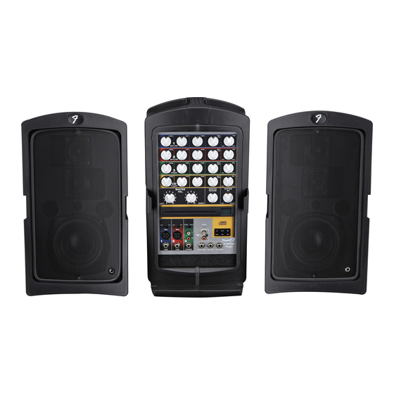
PASSPORT
PD-150
(This is the model name for warranty claims)
p/n 069-2005-003
SERVICE MANUAL
ATTENTION:
WARRANTY SERVICE PROCEDURES
Warranty field service of the Passport PD-150 will be to the Module or PCB Assy. level.
Non-Warranty repairs of course can be to the component level at the Service Center's
discretion. Please note for non-warranty repairs that all parts marked "REF" in the Parts
List will need to be sourced from suppliers other than FMIC.
Fender Musical Instruments Corporation, 8860 East Chaparral Road Suite 100 Scottsdale, AZ 85250
Issued: June, 2007
Advertisement
Table of Contents

Related Manuals for Fender PASSPORT PD-150


Summary of Contents for Fender PASSPORT PD-150
- Page 1 ATTENTION: WARRANTY SERVICE PROCEDURES Warranty field service of the Passport PD-150 will be to the Module or PCB Assy. level. Non-Warranty repairs of course can be to the component level at the Service Center’s discretion. Please note for non-warranty repairs that all parts marked “REF” in the Parts List will need to be sourced from suppliers other than FMIC.
- Page 2 Musical Instruments Corporation. It is not to Corporation. be sold or assigned to another party and is dis- closed solely for use by Fender Authorized Service Centers for purposes of product service Parts marked with two asterisks ( ) indicate the and maintenance.
- Page 3 ® PASSPORT PD-150 (This is the model name for warranty claims) SPECIFICATIONS Model Name: PASSPORT PD-150 Release Number: PR483 Part Number: (120V, 60Hz) US: 069-2005-003 (120V, 60 Hz) DS: 069-2005-903 (240V, 50 Hz) AUS: 069-2005-033 (230V, 50 Hz) UK: 069-2005-043...
- Page 4 ® PASSPORT PD-150 (This is the model name for warranty claims) Product specifications are subject to change without notice SERVICE NOTES The following describes the procedure to dismantle B3. Unscrew nine M3 machine screws from the the PD-150 Cabinets. mixer PCB assembly. B4.
- Page 5 Information is focused for its effective use while may be used as an auxiliary audio signal input. maintaining the security of Fender® proprietary information wherever possible. The stereo mixer section consists of a stereo pair inputs with RCA and 1/4"...
- Page 6 ® PASSPORT PD-150 (This is the model name for warranty claims) The DSP Reverb PCB Module directly drives the biased gates of lateral power FETs Q204 and Q205. The DSP Reverb PCB module receives the input REV/AUX signals at pin 4 of connector CN401. The Speaker short circuit protection is provided by DSP Reverb’s IC’s consist of U404 (AL1101 ADC), U203B.
- Page 7 ® PASSPORT PD-150 (This is the model name for warranty claims) to the rails before you open the set for service to Service Notes on Changes and Upgrades get an indication of a possible power supply fault as it is connected to the rail output. Do not short these A 0.01uF mylar film capacitor has been added to terminals! the VIP ducking circuit to prevent a slight hum that...
- Page 8 + * Access to this part or assembly is controlled. Please contact the FMIC Customer Service Department. ** Safety Requirement part. Replacement must match Safety Agency…–Value, if specified –Type, if specified –Approval Mark(s) if on part. shaded + ** Both a unique Fender® part and a Safety Requirement part as defined above.
- Page 9 + * Access to this part or assembly is controlled. Please contact the FMIC Customer Service Department. ** Safety Requirement part. Replacement must match Safety Agency…–Value, if specified –Type, if specified –Approval Mark(s) if on part. shaded + ** Both a unique Fender® part and a Safety Requirement part as defined above.
- Page 10 + * Access to this part or assembly is controlled. Please contact the FMIC Customer Service Department. ** Safety Requirement part. Replacement must match Safety Agency…–Value, if specified –Type, if specified –Approval Mark(s) if on part. shaded + ** Both a unique Fender® part and a Safety Requirement part as defined above.
- Page 11 + * Access to this part or assembly is controlled. Please contact the FMIC Customer Service Department. ** Safety Requirement part. Replacement must match Safety Agency…–Value, if specified –Type, if specified –Approval Mark(s) if on part. shaded + ** Both a unique Fender® part and a Safety Requirement part as defined above.
- Page 12 + * Access to this part or assembly is controlled. Please contact the FMIC Customer Service Department. ** Safety Requirement part. Replacement must match Safety Agency…–Value, if specified –Type, if specified –Approval Mark(s) if on part. shaded + ** Both a unique Fender® part and a Safety Requirement part as defined above.
- Page 13 + * Access to this part or assembly is controlled. Please contact the FMIC Customer Service Department. ** Safety Requirement part. Replacement must match Safety Agency…–Value, if specified –Type, if specified –Approval Mark(s) if on part. shaded + ** Both a unique Fender® part and a Safety Requirement part as defined above.
- Page 14 + * Access to this part or assembly is controlled. Please contact the FMIC Customer Service Department. ** Safety Requirement part. Replacement must match Safety Agency…–Value, if specified –Type, if specified –Approval Mark(s) if on part. shaded + ** Both a unique Fender® part and a Safety Requirement part as defined above.
- Page 15 + * Access to this part or assembly is controlled. Please contact the FMIC Customer Service Department. ** Safety Requirement part. Replacement must match Safety Agency…–Value, if specified –Type, if specified –Approval Mark(s) if on part. shaded + ** Both a unique Fender® part and a Safety Requirement part as defined above.
- Page 16 + * Access to this part or assembly is controlled. Please contact the FMIC Customer Service Department. ** Safety Requirement part. Replacement must match Safety Agency…–Value, if specified –Type, if specified –Approval Mark(s) if on part. shaded + ** Both a unique Fender® part and a Safety Requirement part as defined above.
- Page 17 + * Access to this part or assembly is controlled. Please contact the FMIC Customer Service Department. ** Safety Requirement part. Replacement must match Safety Agency…–Value, if specified –Type, if specified –Approval Mark(s) if on part. shaded + ** Both a unique Fender® part and a Safety Requirement part as defined above.
- Page 18 + * Access to this part or assembly is controlled. Please contact the FMIC Customer Service Department. ** Safety Requirement part. Replacement must match Safety Agency…–Value, if specified –Type, if specified –Approval Mark(s) if on part. shaded + ** Both a unique Fender® part and a Safety Requirement part as defined above.
- Page 19 + * Access to this part or assembly is controlled. Please contact the FMIC Customer Service Department. ** Safety Requirement part. Replacement must match Safety Agency…–Value, if specified –Type, if specified –Approval Mark(s) if on part. shaded + ** Both a unique Fender® part and a Safety Requirement part as defined above.
- Page 20 + * Access to this part or assembly is controlled. Please contact the FMIC Customer Service Department. ** Safety Requirement part. Replacement must match Safety Agency…–Value, if specified –Type, if specified –Approval Mark(s) if on part. shaded + ** Both a unique Fender® part and a Safety Requirement part as defined above.
- Page 21 + * Access to this part or assembly is controlled. Please contact the FMIC Customer Service Department. ** Safety Requirement part. Replacement must match Safety Agency…–Value, if specified –Type, if specified –Approval Mark(s) if on part. shaded + ** Both a unique Fender® part and a Safety Requirement part as defined above.
- Page 22 ® PASSPORT PD-150 (This is the model name for warranty claims) Service Diagram List Service Diagram (Schematic) .... MIXER Service Diagram (PCB Assembly) .... MIXER PCB Service Diagram (Schematic) .... RCA/XLR INPUT Service Diagram (PCB Assembly) .... RCA/XLR INPUT PCB Service Diagram (Schematic) ....
- Page 23 PASSPORT Mixer Schematic Diagram...
- Page 24 PASSPORT Mixer Section PCB Component Side Mixer Section PCB...
- Page 25 PASSPORT Mixer PCB Copper Side Mixer Section PCB...
- Page 26 RJ1A RCA HSP-206V-03 TAPE OUT RJ1B RCA HSP-206V-03 MIC 1 SVP561P-R WF15 MIC 2 SVP561P-R MIC 3 SVP561P-R RJ1C RCA HSP-206V-03 EXTRA MUSIC RJ1D RCA HSP-206V-03 RJ1E RCA HSP-206V-03 RJ1F RCA HSP-206V-03 PASSPORT RCA Pre Amp Schematic Diagram...
- Page 27 C602 CN602 PWR/OUT U601 CN601 PWR/IN C601 100n C603 1000u/63V REG PCB Component Side C602 CN602 PWR/OUT CN601 U601 PWR/IN C601 100n C603 1000u/63V REG PCB Copper Side RCA/XLR Input PCB Component Side RCA/XLR Input PCB Copper Side PASSPORT RCA/XLR/REG PCB...
- Page 28 PASSPORT Reverb Schematic Diagram...
- Page 29 Reverb PCB Component Side Reverb PCB Copper Side LED201 LED201 04/98 04/98 DUAL LED DUAL LED GR/RED GR/RED 2751-6 LED REV:D REV:D 2751-6 LED LED PCB Component Side LED PCB Copper Side PASSPORT Reverb Section / LED PCB...
- Page 30 PASSPORT SMPS Schematic Diagram...
- Page 31 SMPS PCB Component Side SMPS PCB Copper Side PASSPORT SMPS PCB...
- Page 32 PASSPORT Power Amp Schematic Diagram...
- Page 33 Amplifier PCB Component Side Amplifier PCB Copper Side PASSPORT Power Amp Section PCB...
- Page 34 DC 300V DC 42V DC -42V PASSPORT Test Point Information...
- Page 35 DC 42V DC 8V TP10 DC 15V PASSPORT Test Point Information...
- Page 36 TP11 TP12 TP13 PASSPORT Test Point Information...
- Page 37 TP14 TP15 TP16 PASSPORT Test Point Information...
- Page 38 TP17 TP18 TP19 DC 15V TP20 DC -15V TP21 DC 15V TP22 DC 5V PASSPORT Test Point Information...
- Page 39 TP23 TP24 PASSPORT Test Point Information...
- Page 40 LM317HV R602 R601 CN205 PASSPORT Wiring Diagram...
- Page 41 The following is the legend of the mating connections PCB-P150D11+MIXE PCB-P150D11+RCA MIC1+ MIC1+ MIC1- MIC1- MIC2+ MIC2+ MIC2- MIC2- MIC3+ MIC3+ MIC3- MIC3- RCA IN1 RCA IN1 RCA IN2 RCA IN2 STEREO R STEREO R STEREO L STEREO L TAPE OUT R TAPE OUT R TAPE OUT L TAPE OUT L...
- Page 42 PASSPORT Block Diagram...
- Page 43 NO. DESCRIPTION PART NO. SPEAKER ASSEMBLY SS-EF010C-SPK TOWER HOUSING ASSEMBLY GIG BAG 1497-2132+0 MICROPHONE 1525-1120+0 MIC CABLE 7010-8290+0 MIC CLIP 4133-9100+0 DSUT FILTER 9500-0900+0 Main Unit Ass’y Exploded View Main Unit Ass’y Exploded View...
- Page 44 DESCRIPTION PART NO. FRONT SHEET 8900-1651+0 FRONT PANEL 4153-2770+1 SHIELD PLATE 4133-9550+0 MIXER PCB ASSEMBLY 1723-073A+0000 REVERB PCB ASSEMBLY 1723-075A+0000 RCA/XLR PCB ASSEMBLY 1723-080A+0000 XLR MIC JACK (RCA/XLR ASSY) 2113-1223+0 MIC JACK BRACKET (RCA/XLR) 4133-9570+0 SWITCH COVER 3100-9080+0 3x8MM SCREW TF 2954-3008+3000 M3 FIBER WASHER 2601-3008+0801...
- Page 45 DESCRIPTION PART NO. LATCH ARM 4153-2730+0 LATCH BRACKET 4133-9540+0 LATCH “C” PINS 4133-9430+0 LATCH SPRING 4133-9550+0 LATCH SAFETY CATCH 4153-2740+1 Remark: Each unit contains 4 latch assemblies. Latch Ass’y Exploded View NO. DESCRIPTION PART NO. REAR PANEL 4133-946G+0 AUX POWER CON BRACKET 4133-9510+0 GM FUSE HOLDER HOUSING 4153-1160+0...
- Page 46 Speaker Ass’y Exploded View DESCRIPTION PART NUMBER PD150 8 OHM WOOFER 8900-5870+0 PD150 4 OHM TWEETER 8900-3500+0 SPEAKER BOX PD150 1464-4302+1 BAFFLE PD150 4154-3801+0 STAND PLOG 4154-3841+0 SPEAKER GRILLE 4133-9440+0 BAFFLE GASKET 4153-2880+0 SPRUE CAP (BLK) PD150 4153-2812+0 RED SPRUE CAP 4153-2900+0 M4x14mm SCREW PHPS 2954-4014+3000...
- Page 47 SCREW TAP-BT BH M3X6MM BZ CROSS 2944-3006+3000 PARTITION 4133-9450+0 SIDE PLATE-A 4133-9470+0 DOOR 4153-2750+0 METAL WASHER M3X0.5X8MM BZ 2600-3005+0803 LOCKER DOOE 4153-2760+0 FENDER BADGE PD150 4154-3831+0 F3X8MM SELF TAPPING 2954-3008+3000 SPRUE CAP (BLK) 4153-2812+0 HINGE 4153-2780+0 4X16MM PA 2910-4016+3000 COMPRESSION SPRING 4133-9560+0...
- Page 48 Packing Ass’y Exploded View NO. DESCRIPTION PART NO. GIFT BOX PD150 1434-2104+0-3 2751-P12-0 PLOY BAG 1497-2540+0 2751-P1-0 INNER PAD 1434-2300+0-2 2751-P2-0 INNER PAD 1434-2400+0-1 2751-P3-0 INNER PAD 1434-2500+0-1 2751-P4-0 P.E. FOAM 9500-8700+0 POLYGAB P.E. 04X10X10 1497-2092+0 PD150 UNIT 2751-P7-0 CARTON BOARD 1434-2200+0-1 2751-P6-0 P.E.