Table of Contents
Advertisement
Quick Links
Download this manual
See also:
User Manual
Advertisement
Table of Contents

Related Manuals for National Instruments NI PXIe-1075


Summary of Contents for National Instruments NI PXIe-1075
- Page 1 PXI Express NI PXIe-1075 User Manual NI PXIe-1075 User Manual January 2017 372537C-01...
- Page 2 11500 North Mopac Expressway Austin, Texas 78759-3504 USA Tel: 512 683 0100 For further support information, refer to the NI Services appendix. To comment on NI documentation, refer to the NI website at and enter the Info Code ni.com/info feedback © 2008–2017 National Instruments. All rights reserved.
-
Page 3: Legal Information
National Instruments Corporation. National Instruments respects the intellectual property of others, and we ask our users to do the same. NI software is protected by copyright and other intellectual property laws. Where NI software may be used to reproduce software or other materials belonging to others, you may use NI software only to reproduce materials that you may reproduce in accordance with the terms of any applicable license or other legal restriction. - Page 4 ™ The ExpressCard word mark and logos are owned by PCMCIA and any use of such marks by National Instruments is under license. The mark LabWindows is used under a license from Microsoft Corporation. Windows is a registered trademark of Microsoft Corporation in the United States and other countries.
-
Page 5: Table Of Contents
Optional Equipment......................1-5 EMC Filler Panels ....................1-5 Rack Mount Kit ......................1-5 Slot Blockers......................1-5 NI PXIe-1075 Chassis Backplane Overview..............1-6 Interoperability with CompactPCI................1-6 System Controller Slot....................1-6 Hybrid Peripheral Slots .................... 1-7 PXI Express Peripheral Slots..................1-7 System Timing Slot .................... - Page 6 Contents PXI Express System Configuration with MAX..............2-11 PXI-1 System Configuration ..................2-12 Trigger Configuration in MAX................. 2-12 PXI Trigger Bus Routing..................2-13 Using System Configuration and Initialization Files............2-13 Chapter 3 Maintenance Service Interval ......................... 3-1 Preparation ........................3-1 Cleaning ..........................3-1 Interior Cleaning .......................
-
Page 7: About This Manual
About This Manual NI PXIe-1075 User Manual describes the features of the NI PXIe-1075 chassis and contains information about configuring the chassis, installing the modules, and operating the chassis. Related Documentation The following documents contain information that you might find helpful as you read this manual: •... -
Page 8: Getting Started
Getting Started This chapter describes the key features of the NI PXIe-1075 chassis and lists the kit contents and optional equipment you can order from National Instruments. Unpacking Carefully inspect the shipping container and the chassis for damage. Check for visible damage to the metal work. -
Page 9: Key Features
The chassis’ modular design ensures a high level of maintainability, resulting in a very low mean time to repair (MTTR). The NI PXIe-1075 chassis fully complies with the PXI-5 PXI Express Hardware Specification, offering advanced timing and synchronization features. -
Page 10: Optional Features
NI PXIe-1075 User Manual • Low-jitter internal 10 MHz reference clock for PXI slots with ± 25 ppm stability • Low-jitter internal 100 MHz reference clock for PXIe slots with ± 25 ppm stability • 8 hybrid slots for supporting existing PXI instruments •... -
Page 11: Chassis Description
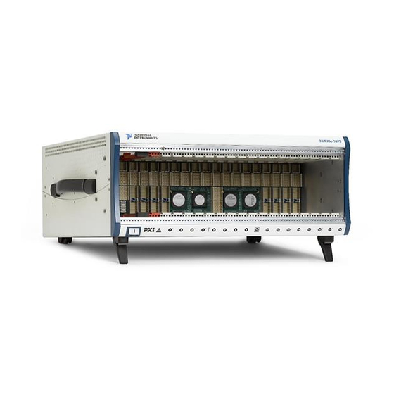
Chassis Description Figures 1-1 and 1-2 show the key features of the NI PXIe-1075 chassis front and back panels. Figure 1-1 shows the front view of the NI PXIe-1075. Figure 1-2 shows the rear view of the NI PXIe-1075. Figure 1-1. Front View of the NI PXIe-1075 Chassis... -
Page 12: Optional Equipment
10 MHz REF IN BNC 14 Air Filter Retainer Optional Equipment Contact National Instruments to order the following options for the NI PXIe-1075 chassis. EMC Filler Panels Optional EMC filler panel kits are available from National Instruments. Rack Mount Kit There are two optional kits for mounting the PXIe-1075 chassis into a rack. -
Page 13: Ni Pxie-1075 Chassis Backplane Overview
NI PXIe-1075 Chassis Backplane Overview This section provides an overview of the backplane features for the NI PXIe-1075 chassis. Interoperability with CompactPCI The design of the NI PXIe-1075 provides you the flexibility to use the following devices in a single PXI Express chassis: •... -
Page 14: Hybrid Peripheral Slots
NI PXIe-1075 User Manual The backplane routes each of the system slots’ x4 PCI Express (PCIe) links to a PCIe switch. The four (4) PCIe switches have x4 PCIe links routed to each peripheral slot as well as x1 links to two (2) PCIe-to-PCI bridges providing 32-bit/33 MHz PCI busses to the hybrid slots. -
Page 15: System Timing Slot
Chapter 1 Getting Started System Timing Slot The System Timing Slot is slot 10. The system timing slot will accept the following peripheral modules: • A PXI Express System Timing Module with x4 or x1 PCI Express link to the system slot through a PCIe switch. -
Page 16: Pxi Local Bus
(user-specified line and directional assignments) can be configured through Measurement & Automation Explorer (MAX). Dynamic routing of triggers (automatic line assignments) is supported through certain National Instruments drivers like NI-DAQmx. Although any trigger line may be routed in either direction, it cannot be Note routed in more than one direction at a time. -
Page 17: System Reference Clock
Chapter 1 Getting Started System Reference Clock The PXIe-1075 chassis supplies PXI_CLK10, PXIe_CLK100 and PXIe_SYNC100 to every peripheral slot with an independent driver for each signal. An independent buffer (having a source impedance matched to the backplane and a skew of less than 1 ns between slots) drives PXI_CLK10 to each peripheral slot. - Page 18 NI PXIe-1075 User Manual To synchronize the system to an external clock, you can drive PXI_CLK10 from an external source through the PXI_CLK10_IN pin on the System Timing Slot. Refer to Table B-5, Connector Pinout for the System Timing Slot, for the pinout. When a 10 MHz clock is detected on this pin, the backplane automatically phase-locks the PXI_CLK10, PXIe_CLK100, and PXIe_SYNC100 signals to this external clock and distributes these signals to the slots.
-
Page 19: Pxie_Sync_Ctrl
Chapter 1 Getting Started PXIe_SYNC_CTRL PXIe_SYNC100 is by default a 10 ns pulse synchronous to PXI_CLK10. The frequency of PXIe_SYNC100 is 10/n MHz, where n is a positive integer. The default for n is 1, giving PXIe_SYNC100 a 100 ns period. However, the backplane allows n to be programmed to other integers. -
Page 20: Installation And Configuration
Installation and Configuration This chapter describes how to prepare and operate the NI PXIe-1075 chassis. Before connecting the chassis to a power source, read this chapter and the Read Me First: Safety and Electromagnetic Compatibility document included with your kit. -
Page 21: Chassis Cooling Considerations
Providing Adequate Clearance The primary cooling exhaust vent for the NI PXIe-1075 is on the top of the chassis. The primary intake vent is on the rear of the chassis where the air is filtered as it enters the power supply shuttle. -
Page 22: Chassis Ambient Temperature Definition
NI PXIe-1075 User Manual Figure 2-2. NI PXIe-1075 Vents Primary Air Exhaust Vent Primary Air Intake Vent Air Filter Secondary Air Intake/Exhaust Vents (both sides) Chassis Ambient Temperature Definition The chassis fan control system uses intake air temperature as the input for controlling fan speeds when in Auto Fan Speed mode. -
Page 23: Setting Fan Speed
Chapter 2 Installation and Configuration Setting Fan Speed The fan-speed selector switch is on the rear panel of the NI PXIe-1075 chassis. Refer to Figure 1-2, Rear View of the NI PXIe-1075 Chassis, to locate the fan-speed selector switch. Select High for maximum cooling performance or Auto for improved acoustic performance. -
Page 24: Connecting To Power Source
This section contains general installation instructions for installing a PXI Express system controller in a NI PXIe-1075 chassis. Refer to your PXI Express system controller user manual for specific instructions and warnings. To install a system controller, complete the following... - Page 25 Figure 2-4 shows a PXI Express system controller installed in the system controller slot of a NI PXIe-1075 chassis. You can place CompactPCI, CompactPCI Express, PXI, or PXI Express modules in other slots depending on the slot type.
-
Page 26: Installing Peripheral Modules
Started, for a description of the various slot types. This section contains general installation instructions for installing a peripheral module in a NI PXIe-1075 chassis. Refer to your peripheral module user manual for specific instructions and warnings. To install a module, complete the following steps: Inspect the slot for any physical damage or bent pins before installing the peripheral module. -
Page 27: Power Inhibit Switch Led Indicator
Peripheral Module Front Panel Mounting Screws (2x) Injector/Ejector Rail NI PXI Express System Controller Injector/Ejector Handle NI PXIe-1075 Chassis PXI Express Peripheral Module Power Inhibit Switch LED Indicator The chassis power inhibit switch has an integrated LED. Refer to Figure 1-1,... -
Page 28: Remote Voltage Monitoring And Control
Remote Voltage Monitoring and Control The NI PXIe-1075 chassis supports remote voltage monitoring and inhibiting through a female 9-pin D-SUB (DB-9) connector located on the rear panel as shown in Figure 1-2, Rear View of the NI PXIe-1075 Chassis. -
Page 29: Inhibit Mode Switch
Chapter 2 Installation and Configuration You can use a digital voltmeter to ensure all voltage levels in the NI PXIe-1075 chassis are within the allowable limits. Referring to Table 2-2, connect one lead of the voltmeter to a supply pin on the remote voltage monitoring connector (9-pin D-SUB) on the rear panel. Refer to Table 2-1 for a pinout diagram of the remote voltage monitoring connector. -
Page 30: Pxi_Clk10 Rear Connectors
NI PXIe-1075 User Manual PXI_CLK10 Rear Connectors There are two BNC connectors on the rear of the NI PXIe-1075 chassis for PXI_CLK10, as shown in Figure 1-2, Rear View of the NI PXIe-1075 Chassis. The connectors are labeled IN and OUT. -
Page 31: Pxi-1 System Configuration
Dynamic reservation/routing/deallocation is on the fly within a user program based upon National Instruments APIs such as NI-DAQmx. Static reservation of trigger lines can be implemented by the user in MAX through the Triggers tab. -
Page 32: Pxi Trigger Bus Routing
Click the Apply button. PXI Trigger Bus Routing Some National Instruments chassis, such as the PXI-1075 and the PXI-1044/1045, have the capability to route triggers from one bus to others within the same chassis using the Trigger Routing tab in MAX, as shown in Figure 2-6. - Page 33 Chapter 2 Installation and Configuration Device drivers and other utility software read the file to obtain system pxisys.ini information. The device drivers should have no need to directly read the file. chassis.ini For detailed information regarding initialization files, refer to the PXI Express specification at www.pxisa.org 2-14 | ni.com...
-
Page 34: Maintenance
Maintenance This chapter describes basic maintenance procedures you can perform on the NI PXIe-1075 chassis. Disconnect the power cable prior to servicing a NI PXIe-1075 chassis. Caution Service Interval Clean the chassis fan filters at a maximum interval of six months. Depending on the amount of use and ambient dust levels in the operating environment, the filters may require more frequent cleaning. -
Page 35: Exterior Cleaning
Cleaning the Fan Filters A dirty fan filter can dramatically affect the cooling performance of an NI PXIe-1075 chassis. Clean the filter whenever it becomes visibly dirty. You can easily remove the chassis air filters from the rear of the chassis by removing the filter retainer. -
Page 36: Replacing The Modular Power Supply Shuttle
Disconnect the power cable from the power supply shuttle on the back of the chassis. Identify the ten mounting screws for the NI PXIe-1075 that attach the power supply shuttle to the chassis. Refer to Figure 1-2,... -
Page 37: Installation
The fan-speed selector switch is on the rear panel of the power supply shuttle. Refer to Figure 1-2, Rear View of the NI PXIe-1075 Chassis, to locate the fan-speed selector. Select High for maximum cooling performance (recommended) or Auto for quieter operation. Set the Inhibit Mode switch to the Default position. -
Page 38: Appendix A Specifications
Specifications This appendix contains specifications for the NI PXIe-1075 chassis. Specifications are subject to change without notice. Caution Electrical AC Input Input voltage rating 100 to 120 VAC, 220 to 240 VAC Operating voltage range 90 to 120 VAC, 200 to 264 VAC... - Page 39 Chapter A Specifications more information, refer to the Inhibit Mode Switch section of Chapter 2, Installation and Configuration. DC Output DC current capacity (I Voltage Maximum Current +3.3 V 60 A +5 V 48 A +12 V 62 A -12 V 2.0 A Maximum total usable power is 791 W.
- Page 40 NI PXIe-1075 User Manual Load regulation Voltage Load Regulation +3.3 V <5% +12 V <5% +5 V <5% -12 V <5% Maximum ripple and noise (20 MHz bandwidth) Voltage Maximum Ripple and Noise +3.3 V 50 mV +12 V 50 mV...
-
Page 41: Operating Environment
Chapter A Specifications Power supply cooling exhaust Left side of chassis Clearance for intake/exhaust vents 1.75 in. (44.45 mm) for top and side vents 3.00 in. (76.20 mm) for back vents Maximum fan cleaning interval 6 months Fan filter material 30 ppi, 3/32 in. -
Page 42: Shock And Vibration
NI PXIe-1075 User Manual Shock and Vibration Operational shock 30 g peak, half-sine, 11 ms pulse (Tested in accordance with IEC 60068-2-27. Meets MIL-PRF-28800F Class 2 limits.) Random Vibration 5 to 500 Hz, 0.3 g Acoustic Emissions Sound Pressure Level (at Operator Position) (Tested in accordance with ISO 7779. -
Page 43: Electromagnetic Compatibility
Certification column. Environmental Management National Instruments is committed to designing and manufacturing products in an environmentally responsible manner. NI recognizes that eliminating certain hazardous substances from our products is beneficial not only to the environment but also to NI customers. - Page 44 NI PXIe-1075 User Manual National Instruments (RoHS) National Instruments RoHS ni.com/ (For information about China RoHS compliance, environment/rohs_china go to ni.com/environment/rohs_china Backplane Size 3U-sized; one system slot (with three system expansion slots) and 17 peripheral slots. Compliant with IEEE 1101.10 mechanical packaging.
- Page 45 Chapter A Specifications 100 MHz System Reference Clock: PXIe_CLK100 and PXIe_SYNC100 Maximum slot-to-slot skew 100 ps Accuracy ±25 ppm max. (guaranteed over the operating temperature range) Maximum jitter 3 ps RMS phase-jitter (10 Hz to 12 kHz range) 2 ps RMS phase-jitter (12 kHz to 20 MHz range) Duty-factor for PXIe_CLK100 45 to 55% Absolute single-ended voltage swing...
- Page 46 Backplane differential impedance For PXIe slot to PXI_DSTAR mapping refer to the System Timing Slot Note section of Chapter 1, Getting Started. For other specifications, the NI PXIe-1075 complies with the PXI-5 PXI Express Hardware Specification. © National Instruments | A-9...
- Page 47 Chapter A Specifications Mechanical Overall dimensions Standard chassis Height 6.97 in. (177.1 mm) Width 18.30 in. (464.8 mm) Depth 18.40 in. (467.4 mm) 0.57 in. (14.5 mm) is added to height when feet are installed. When tilted with Note front feet extended on table top, height is increased approximately 2.08 in. (52.8 mm) in front and 0.583 in.
- Page 48 NI PXIe-1075 User Manual Figures A-1 and A-2 show the NI PXIe-1075 chassis dimensions. The holes shown are for the installation of the optional rack mount kits. You can install those kits on the front or rear of the chassis, depending on which end of the chassis you want to face toward the front of the instrument cabinet.
- Page 49 Chapter A Specifications Figure A-2. NI PXIe-1075 Chassis Dimensions (Bottom) Dimensions are in inches (millimeters) 12.700 (322.58) 2.524 (64.11) 15.504 (393.8) 1.017 (25.83) A-12 | ni.com...
- Page 50 The chassis shown in Figure A-3 is representative of the NI PXI-1044/1045 Note and NI PXIe-1075 product line. For more information on rack mounting the NI PXIe-1075 chassis, refer to the printed installation guide included with your rack mount kit. © National Instruments | A-13...
- Page 51 Pinouts This appendix describes the connector pinouts for the NI PXIe-1075 chassis backplane. Figure B-1 illustrates the types of PXIe connectors by providing a layout of the PXI Express system controller slot (slot 1). Table B-1 shows the XP4 Connector Pinout for the System Controller slot.
- Page 52 Appendix B Pinouts System Controller Slot Pinouts Figure B-1. PXI Express System Controller Slot Layout XP4 Connector XP2 Connector XP3 Connector XP1 Connector B-2 | ni.com...
- Page 53 Table B-1. XP4 Connector Pinout for the System Controller Slot 5Vaux SYSEN# WAKE# ALERT# PXI_TRIG3 PXI_TRIG4 PXI_TRIG5 PXI_TRIG6 PXI_TRIG2 PXI_STAR PXI_CLK10 PXI_TRIG1 PXI_TRIG0 PXI_TRIG7 PXI_LBR6 Table B-2. XP3 Connector Pinout for the System Controller Slot PWR_OK PS_ON# LINKCAP PWRBTN# SMBDAT SMBCLK 4RefClk+ 4RefClk-...
- Page 54 Table B-2. XP3 Connector Pinout for the System Controller Slot (Continued) 1PETp3 1PETn3 1PERp3 1PERn3 2PETp0 2PETn0 2PETp1 2PETn1 2PERp1 2PERn1 2PERp0 2PERn0 2PETp2 2PETn2 2PERp2 2PERn2 2PETp3 2PETn3 3PETp0 3PETn0 3PERp0 3PERn0 2PERp3 2PERn3 Table B-3. XP2 Connector Pinout for the System Controller Slot 3PETp1 3PETn1 3PERp1...
- Page 55 NI PXIe-1075 User Manual Table B-4. XP1 Connector Pinout for the System Controller Slot Pins Signals 3.3V System Timing Slot Pinouts Figure B-2. PXI Express System Timing Slot Layout XP4 Connector TP2 Connector XP3 Connector TP1 Connector © National Instruments | B-5...
- Page 56 Table B-5. XP4 Connector Pinout for the System Timing Slot SYSEN# WAKE# ALERT# 3.3V 3.3V 3.3V PXI_TRIG3 PXI_TRIG4 PXI_TRIG5 PXI_TRIG6 PXI_TRIG2 ATNLED PXI_CLK10_IN PXI_CLK10 PXI_TRIG1 PXI_TRIG0 ATNSW# PXI_TRIG7 PXIe_SYNC_CTRL PXI_LBL6 PXI_LBR6 Table B-6. XP3 Connector Pinout for the System Timing Slot PXIe_CLK100 PXIe_ PXIe_...
- Page 57 Table B-6. XP3 Connector Pinout for the System Timing Slot (Continued) 1PETp2 1PETn2 1PERp2 1PERn2 1PERp1 1PERn1 1PETp3 1PETn3 1PERp3 1PERn3 1PETp4 1PETn4 1PETp5 1PETn5 1PERp5 1PERn5 1PERp4 1PERn4 1PETp6 1PETn6 1PERp6 1PERn6 1PETp7 1PETn7 1PERp7 1PERn7 Table B-7. TP2 Connector Pinout for the System Timing Slot PXIe_ PXIe_ PXIe_...
- Page 58 Table B-7. TP2 Connector Pinout for the System Timing Slot (Continued) PXIe_ PXIe_ PXI_STAR6 PXI_STAR7 PXIe_ PXIe_ DSTARB2+ DSTARB2- DSTARB10+ DSTARB10- PXIe_ PXIe_ PXI_STAR8 PXI_STAR9 PXIe_ PXIe_ DSTARA2+ DSTARA2- DSTARC11+ DSTARC11- PXIe_ PXIe_ PXI_ PXI_ PXIe_ PXIe_ DSTARC3+ DSTARC3- STAR10 STAR11 DSTARA11+ DSTARA11-...
- Page 59 Table B-8. TP1 Connector Pinout for the System Timing Slot (Continued) PXIe_ PXIe_ PXIe_ PXIe_ PXIe_ PXIe_ DSTARB5+ DSTARB5- DSTARB16+ DSTARB16- DSTARB13+ DSTARB13- PXIe_ PXIe_ PXIe_ PXIe_ PXIe_ PXIe_ DSTARA5+ DSTARA5- DSTARA7+ DSTARA7- DSTARC14+ DSTARC14- PXIe_ PXIe_ PXI_STAR16 PXIe_ PXIe_ DSTARC6+ DSTARC6- DSTARA14+...
- Page 60 Appendix B Pinouts Hybrid Slot Pinouts Figure B-3. PXI Express System Hybrid Slot Layout XP4 Connector XP3 Connector P1 Connector B-10 | ni.com...
- Page 61 Table B-9. XP4 Connector Pinout for the Hybrid Slot 5Vaux SYSEN# WAKE# ALERT# 3.3V 3.3V 3.3V PXI_TRIG3 PXI_TRIG4 PXI_TRIG5 PXI_TRIG6 PXI_TRIG2 ATNLED PXI_STAR PXI_CLK10 PXI_TRIG1 PXI_TRIG0 ATNSW# PXI_TRIG7 PXI_LBL6 PXI_LBR6 Table B-10. XP3 Connector Pinout for the Hybrid Slot PXIe_ PXIe_ PXIe_ PXIe_...
- Page 62 Table B-10. XP3 Connector Pinout for the Hybrid Slot (Continued) 1PETp2 1PETn2 1PERp2 1PERn2 1PERp1 1PERn1 1PETp3 1PETn3 1PERp3 1PERn3 1PETp4 1PETn4 1PETp5 1PETn5 1PERp5 1PERn5 1PERp4 1PERn4 1PETp6 1PETn6 1PERp6 1PERn6 1PETp7 1PETn7 1PERp7 1PERn7 Table B-11. P1 Connector Pinout for the Hybrid Slot REQ64# ENUM# 3.3V...
- Page 63 Table B-11. P1 Connector Pinout for the Hybrid Slot (Continued) DEVSEL# V(I/O) STOP# LOCK# 3.3V FRAME# IRDY# BD_SEL# TRDY# 12 to 14 Key Area AD[18] AD[17] AD[16] C/BE[2]# AD[21] 3.3V AD[20] AD[19] C/BE[3]# IDSEL AD[23] AD[22] AD[26] V(I/O) AD[25] AD[24] AD[30] AD[29] AD[28]...
- Page 64 • System Integration—If you have time constraints, limited in-house technical resources, or other project challenges, National Instruments Alliance Partner members can help. To learn more, call your local NI office or visit ni.com/alliance © National Instruments | C-1...
- Page 65 Appendix C NI Services • Training and Certification—The NI training and certification program is the most effective way to increase application development proficiency and productivity. Visit for more information. ni.com/training – The Skills Guide assists you in identifying the proficiency requirements of your current application and gives you options for obtaining those skills consistent with your time and budget constraints and personal learning preferences.
- Page 66 Symbols ° Degrees. Equal or greater than. Equal or less than. Percent. Amperes. Alternating current. ANSI American National Standards Institute. Auto Automatic fan speed control. American Wire Gauge. © National Instruments | G-1...
- Page 67 Glossary backplane An assembly, typically a printed circuit board, with connectors and signal paths that bus the connector pins. Bayonet Neill Concelman connector; a commonly used coaxial connector. Celsius. Cubic feet per minute. Code of Federal Regulations. Centimeters. CompactPCI An adaptation of the Peripheral Component Interconnect (PCI) Specification 2.1 or later for industrial and/or embedded applications requiring a more robust mechanical form factor than desktop PCI.
- Page 68 NI PXIe-1075 User Manual efficiency Ratio of output power to input power, expressed as a percentage. Electronic Industries Association. Electromagnetic Compatibility. Electromagnetic Interference. Federal Communications Commission. filler panel A blank module front panel used to fill empty slots in the chassis.
- Page 69 Glossary Inches. inhibit To turn off. jitter A measure of the small, rapid variations in clock transition times from their nominal regular intervals. Units: seconds RMS. Kilograms. Kilometers. Pounds. Light emitting diode. line regulation The maximum steady-state percentage that a DC voltage output will change as a result of a specified change in input AC voltage (step change from 90 VAC to 132 VAC or 180 VAC to 264 VAC).
- Page 70 NI PXIe-1075 User Manual NEMA National Electrical Manufacturers Association. National Instruments. power supply shuttle A removable module that contains the chassis power supply. PCI eXtensions for Instrumentation. PXI_CLK10 10 MHz PXI system reference clock. Relative humidity. Root mean square. Seconds.
- Page 71 Glossary system reference A 10 MHz clock, also called PXI_CLK10, that is distributed to all clock peripheral slots in the chassis, as well as a BNC connector on the rear of chassis labeled 10 MHz REF OUT. The system reference clock can be used for synchronization of multiple modules in a measurement or control system.
- Page 72 PXIe-1075 backplane, 1-6 chassis initialization file, 2-13 configuration in MAX (figure), 2-11 configuration in MAX (figure), 2-11 configuration. See installation, configuration, connecting safety ground, 2-4 and operation filler panel installation, 2-4 connector pinouts. See pinouts © National Instruments | I-1...
- Page 73 2-4 using as restart (figure), 1-12 site considerations, 2-2 rack mounting, 2-4 slot blocker installation, 2-4 rear view of NI PXIe-1075 chassis, 1-5 testing power up, 2-5 safety ground, connecting, 2-4 unpacking the PXIe-1075, 1-1 specifications, A-7...
- Page 74 PXI Express peripheral slots, description, 1-7 CE compliance, A-6 PXI Express system controller, 2-5 chassis cooling, A-3 figure, 2-6 dimensions (figure), A-11, A-12 installing in a NI PXIe-1075 chassis electrical (figure), 2-7 AC input, A-1 PXI local bus, routing, 1-9 DC output, A-2...
- Page 75 TP2 connector (table), B-7 XP3 connector (table), B-6 XP4 connector (table), B-6 testing power up, 2-5 trigger bus, 1-9 unpacking the NI PXIe-1075 chassis, 1-1 voltage monitoring connector. See DB-9 connector voltages at voltage monitoring connector (DB-9) (table), 2-10 I-4 | ni.com...