
Related Manuals for YASKAWA SGMAS


Summary of Contents for YASKAWA SGMAS
- Page 1 YASKAWA YASKAWA Series SGM S/SGDS □ USER'S MANUAL For SynqNet Communications SGMAS/SGMPS/SGMSS/SGMCS Servomotors SGDS- A SERVOPACK □□□ □ YASKAWA MANUAL NO. SIEP S800000 25A...
- Page 2 Yaskawa. No patent liability is assumed with respect to the use of the information contained herein. Moreover, because Yaskawa is con- stantly striving to improve its high-quality products, the information contained in this manual is subject to change without notice.
-
Page 3: About This Manual
Description of Technical Terms The terms in this manual are defined as follows: • Servomotor = Σ-III Series SGMAS, SGMPS, SGMSS, SGMCS (direct drive) servomotor. • SERVOPACK = Σ-III Series SGDS amplifier. • Servodrive = A set including a servomotor and servo amplifier. - Page 4 ■ Visual Aids The following aids are used to indicate certain types of information for easier reference. • Indicates important information that should be memorized, including precautions such as alarm dis- IMPORTANT plays to avoid damaging the devices. • Indicates supplemental information. INFO •...
-
Page 5: Safety Information
The warning symbols for ISO and JIS standards are different, as shown below. The ISO symbol is used in this manual. Both of these symbols appear on warning labels on Yaskawa products. Please abide by these warning labels regardless of which symbol is used. - Page 6 Notes for Safe Operation Read this manual thoroughly before checking products on delivery, storage and transportation, installation, wiring, operation and inspection, and disposal of the AC servodrives. WARNING • Never touch any rotating motor parts while the motor is running. Failure to observe this warning may result in injury.
- Page 7 WARNING • Do not come close to the machine immediately after resetting momentary power loss to avoid an unexpected restart. Take appropriate measures to ensure safety against an unexpected restart. Failure to observe this warning may result in injury. • Do not modify the product. Failure to observe this warning may result in injury or damage to the product.
- Page 8 Installation CAUTION • Never use the products in an environment subject to water, corrosive gases, inflammable gases, or combustibles. Failure to observe this caution may result in electric shock or fire. • Do not step on or place a heavy object on the product. Failure to observe this caution may result in injury.
- Page 9 Wiring CAUTION • Do not connect a three-phase power supply to the U, V, or W output terminals. Failure to observe this caution may result in injury or fire. • Securely connect the power supply terminal screws and motor output terminal screws. Failure to observe this caution may result in fire.
- Page 10 CAUTION • Take appropriate and sufficient countermeasures for each when installing systems in the following locations. Failure to observe this caution may result in damage to the product. • Locations subject to static electricity or other forms of noise. • Locations subject to strong electromagnetic fields and magnetic fields. •...
-
Page 11: Maintenance And Inspection
When this manual is revised, the manual code is updated and the new manual is published as a next edition. • If the manual must be ordered due to loss or damage, inform your nearest Yaskawa representative or one of the offices listed on the back of this manual. -
Page 12: Table Of Contents
2.1 Servomotor Model Designations - - - - - - - - - - - - - - - - - - - - 2-2 2.1.1 Model SGMAS/SGMPS/SGMSS - - - - - - - - - - - - - - - - - - - - - - - - - - - 2-2 2.1.2 Model SGMCS - - - - - - - - - - - - - - - - - - - - - - - - - - - - - - - - - - - - - - - 2-4... - Page 13 3.3.2 Single-phase 200 V, 50 W to 400W Models- - - - - - - - - - - - - - - - - - - -3-7 3.3.3 Three-phase 200 V, 1.0 kW Models - - - - - - - - - - - - - - - - - - - - - - - - -3-8 3.3.4 Single-phase 200 V, 750 W Model - - - - - - - - - - - - - - - - - - - - - - - - - -3-9 3.3.5 Three-phase 200 V, 1.5 kW to 3.0 kW Models - - - - - - - - - - - - - - - - - 3-10 3.4 SERVOPACK Power Losses - - - - - - - - - - - - - - - - - - - - - - 3-11...
- Page 14 5 Wiring 5.1 Wiring Main Circuit - - - - - - - - - - - - - - - - - - - - - - - - - - - - - - 5-2 5.1.1 Names and Descriptions of Main Circuit Terminals - - - - - - - - - - - - - - 5-2 5.1.2 Wiring Main Circuit Terminal Block (Spring Type) - - - - - - - - - - - - - - - 5-3 5.1.3 Typical Main Circuit Wiring Examples - - - - - - - - - - - - - - - - - - - - - - - 5-4 5.2 Wiring Encoders- - - - - - - - - - - - - - - - - - - - - - - - - - - - - - - - 5-7...
- Page 15 8 Adjustments 8.1 Torque Filters - - - - - - - - - - - - - - - - - - - - - - - - - - - - - - - - - - 8-2 8.2 Analog Monitor- - - - - - - - - - - - - - - - - - - - - - - - - - - - - - - - - 8-5 9 Inspection, Maintenance, and Troubleshooting 9.1 Troubleshooting - - - - - - - - - - - - - - - - - - - - - - - - - - - - - - - - 9-2...
-
Page 16: Outline
Outline 1.1 Checking Products - - - - - - - - - - - - - - - - - - - - - - - - - - - - - - 1-2 1.1.1 Check Items - - - - - - - - - - - - - - - - - - - - - - - - - - - - - - - - - - - - - - - - - 1-2 1.1.2 Servomotors - - - - - - - - - - - - - - - - - - - - - - - - - - - - - - - - - - - - - - - - - 1-2 1.1.3 SERVOPACKs - - - - - - - - - - - - - - - - - - - - - - - - - - - - - - - - - - - - - - - 1-3 1.2 Product Part Names - - - - - - - - - - - - - - - - - - - - - - - - - - - - - 1-4... -
Page 17: Checking Products
Check the overall appearance, and check for damage or scratches that may have occurred during shipping. If any of the above items are faulty or incorrect, contact your Yaskawa representative or the dealer from whom you purchased the products. 1.1.2 Servomotors... -
Page 18: Servopacks
AC SERVO MOTOR Servomotor model TYPE SGMCS-45M3A11 45 N Ratings CONT ins F O/N 252909-101 Order number Serial number 842000045 DATE 0306 YASKAWA ELECTRIC MADE IN JAPAN 1.1.3 SERVOPACKs Nameplate SERVOPACK SERVOPACK SGDS-10A72A MODEL model AC-INPUT AC-OUTPUT Applicable Applicable power supply... -
Page 19: Product Part Names
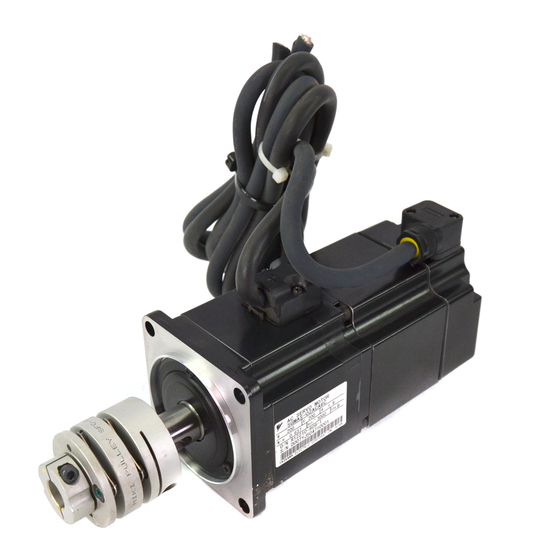
1 Outline 1.2.1 Servomotors 1.2 Product Part Names 1.2.1 Servomotors (1) Types SGMAS and SGMPS without Gears and Brakes SGMAS or SGMPS-01 to 04 for 100 W to 400 W SGMPS-08, 15 for 750 W, 1.5 kW Servomotor Encoder Servomotor... -
Page 20: Servopacks
1.2 Product Part Names (4) Type SGMCS Direct-drive (Medium-capacity Series) Rotary axis Mounting flange Frame Nameplate Servomotor connector Encoder connector 1.2.2 SERVOPACKs Refer to 2.2 SERVOPACK Model Designations. Lights when the control power supply is on. Lights when an alarm exists. Used for I/O with a digital operator. -
Page 21: Examples Of Servo System Configurations
1 Outline 1.3 Examples of Servo System Configurations This section describes examples of basic servo system configuration. - Page 22 1.3 Examples of Servo System Configurations (1) Connecting to SGMAS and SGMPS Servomotors Power supply Single-phase 100 or 200 VAC Note: For connecting the AC/DC reactor, refer to 5.4.5 AC/DC Reactor for Harmonic Suppression. Molded-case circuit breaker (MCCB) Protects the power supply...
- Page 23 1 Outline (2) Connecting to SGMAS and SGMPS Servomotors Connect the main circuit cable and encoder cable to SGMAS or SGMPS (100 W to 400 W) servomotor in the following manner. Do not directly touch the connector pins provided with the servomotor. Particularly, the encoder may be IMPORTANT damaged by static electricity, etc.
- Page 24 1.3 Examples of Servo System Configurations (3) Connecting to SGMSS Servomotors Power supply Single-phase 200 VAC Notes: 1. For single-phase 200V 800W SERVOPACKS, R S T the terminal L3 is not used. Do not connect. Molded-case circuit breaker 2. Remove the lead wire between the terminals (MCCB) B2 and B3 on the SERVOPACK before Protects the power supply...
- Page 25 1 Outline (4) Connecting to SGMCS Servomotor Power supply Note: For connecting the AC/DC reactor, Single-phase 100 or 200 VAC refer to 5.4.5 AC/DC Reactor for Harmonic Suppression. Molded-case circuit breaker (MCCB) Protects the power supply line by shutting the circuit OFF when overcurrent is detected.
-
Page 26: Applicable Standards
∗2 Model Certification Standards (UL File No.) Standards CSA C22.2 • SGDS UL508C(E147823) SERVOPACK No.14 • SGMAS • SGMPS CSA C22.2 UL1004(E165827) Servomotor No.100 • SGMSS • SGMCS * 1. Underwriters Laboratories Inc. * 2. Canadian Standards Association. Note: Certification is pending for the following SERVOPACKs. -
Page 27: Selections
2.1 Servomotor Model Designations - - - - - - - - - - - - - - - - - - - - - 2-2 2.1.1 Model SGMAS/SGMPS/SGMSS - - - - - - - - - - - - - - - - - - - - - - - - - - - 2-2 2.1.2 Model SGMCS - - - - - - - - - - - - - - - - - - - - - - - - - - - - - - - - - - - - - - - 2-4... -
Page 28: Servomotor Model Designations
This section explains how to check the servomotor model and ratings. The alphanumeric codes after SGM S indicate the specifications. 2.1.1 Model SGMAS/SGMPS/SGMSS (1) Without Gears SGMAS 01 A C A 2 1 Options Σ-III Series SGMAS, SGMPS Code Specifications and SGMSS servomotor Without options With 90-VDC brake With 24-VDC brake... - Page 29 Note: The number of encoder pulses is 32768 P/Rev. Design Revision Order Gear Type Code Design Revision Order Code Specifications SGMAS/SGMPS/SGMSS HDS planetary low-backlash gear (SGMAS/SGMPS Standard backlash gear (SGMAS/SGMPS) SGMPS (IP67 specification) Low-backlash gear (SGMSS) Note: SGMPS servomotors conform to IP67, but the gears do not.
-
Page 30: Model Sgmcs
2 Selections 2.1.2 Model SGMCS 2.1.2 Model SGMCS SGMCS 02 B 3 B 1 1 Σ-III Series servomotor SGMCS Rated Torque (N m) Motor Outer Diameter (mm) Brake Specifications Code Specifications B (φ135) C (φ175) D (φ230) E (φ290) M (φ280) N (φ360) Code Specifications Without brake... -
Page 31: Servopack Model Designations
2.2 SERVOPACK Model Designations 2.2 SERVOPACK Model Designations Select the SERVOPACK according to the applied servomotor. ∗ SGDS - A 72 A Mounting Method Σ-III Series SGDS Code Mounting Method SERVOPACK Base-mounted − as standard Rack-mounted Design Revision Order Rated Output of Starts from A Applicable Servomotor Code... -
Page 32: Σ-Iii Series Servopacks And Applicable Servomotors
Σ-III Series SGDS SERVOPACK Σ-III Series SGM S servomotor Single-phase Single-phase Three-phase 100 VAC 200 VAC 200 VAC − A5A (50 W) SGMAS − 01A (100 W) (Super High Power − C2A (150 W) Capacity) − 02A (200 W) −... -
Page 33: Selecting Cables
2.4 Selecting Cables 2.4 Selecting Cables 2.4.1 Cables for SGMAS and SGMPS Servomotor • Cable Connection for Standard Wiring Distance SGMAS/SGMPS SERVOPACK SGMPS-08, 15 Servomotor for 750 W, 1.5 kW Servomotor main circuit Encoder cable cable (for relay) (for relay) - Page 34 2 Selections 2.4.1 Cables for SGMAS and SGMPS Servomotor • Encoder Cable Extension from 20 m (65.5 ft) up to 50 m (164 ft) SGMAS/SGMPS SGMPS 08,15 Servomotor for 750 W, 1.5 kW SERVOPACK Relay encoder cable extension (SERVOPACK end)
- Page 35 10 m both ends JZSP-CSP01-10 JZSP-CSP21-10 (32.8 ft) (For incremen- 15 m tal encoder) JZSP-CSP01-15 JZSP-CSP21-15 (49.2 ft) SGMAS for 20 m JZSP-CSP01-20 JZSP-CSP21-20 50 to 1.15 kW, (65.5 ft) SGMPS for JZSP-CSP05-03 JZSP-CSP25-03 (9.84 ft) 100 to 400 W...
- Page 36 2 Selections 2.4.1 Cables for SGMAS and SGMPS Servomotor (cont’d) Name Servomotor Length Type Specifications Model Standard Type Flexible Type * JZSP-CMP03-03 JZSP-CMP13-03 (9.84 ft) JZSP-CMP03-05 JZSP-CMP13-05 Cable with (16.4 ft) SERVOPACK end Encoder end SGMAS loose wire at 10 m 50 to 1.15 kW,...
- Page 37 Name Servomotor Length Type Specifications Model Standard Type Flexible Type * JZSP-CSM01-03 JZSP-CSM21-03 (9.84 ft) JZSP-CSM01-05 JZSP-CSM21-05 SGMAS (16.4 ft) 50 to 150 W, 10 m JZSP-CSM01-10 JZSP-CSM21-10 (32.8 ft) SGMPS 15 m 100 W JZSP-CSM01-15 JZSP-CSM21-15 (49.2 ft) 20 m...
- Page 38 2 Selections 2.4.1 Cables for SGMAS and SGMPS Servomotor (cont’d) Name Servomotor Length Type Specifications Model Standard Type Flexible Type * − JZSP-CMM20-03 (9.84 ft) − JZSP-CMM20-05 (16.4 ft) SERVOPACK end Servomotor end 10 m Without brakes SGMPS − JZSP-CMM20-10 (Cont.)
- Page 39 SGMPS − JZSP-CMM30-10 1.5 kW (32.8 ft) 15 m − JZSP-CMM30-15 (49.2 ft) 20 m − JZSP-CMM30-20 (65.5 ft) SGMAS Servo- 50 to 150 W motor JZSP-CSM9-1 Main Cir- SGMPS cuit 100 W Caulking Cables (Exclusive tool is required.) SGMAS (Cont.)
- Page 40 2 Selections 2.4.1 Cables for SGMAS and SGMPS Servomotor (cont’d) Name Servomotor Length Type Specifications Model Standard Type Flexible Type * JZSP-CSM90-05 JZSP-CSM80-05 (16.4 ft) SGMAS 10 m JZSP-CSM90-10 JZSP-CSM80-10 50 to 600 W (32.8 ft) 15 m SGMPS JZSP-CSM90-15 JZSP-CSM80-15 (49.2 ft)
-
Page 41: Cables For Sgmss Servomotor
2.4 Selecting Cables 2.4.2 Cables for SGMSS Servomotor • Cable Connection for Standard Wiring Distance SGDS- SERVOPACK 2-15... - Page 42 2 Selections 2.4.2 Cables for SGMSS Servomotor • Encoder Cable Extension from 20 m (65.5 ft) up to 50 m (164 ft) SGDS- SERVOPACK Relay encoder cable extension (SERVOPACK end) To be assembled by the customer. SGMSS Servomotor 2-16...
- Page 43 2.4 Selecting Cables Name Length Type Specification Standard Type Flexible Type JZSP-CMP03-03 JZSP-CMP13-03 (9.84 ft) JZSP-CMP03-05 JZSP-CMP13-05 Cable with loose SERVOPACK end Encoder end (16.4 ft) wire at encoder 10 m JZSP-CMP03-10 JZSP-CMP13-10 (32.8 ft) (For incremen- 15 m tal encoder) JZSP-CMP03-15 JZSP-CMP13-15 (49.2 ft)
- Page 44 2 Selections 2.4.2 Cables for SGMSS Servomotor Name Length Type Specification Standard Type Flexible Type JZSP-CSP06-03 JZSP-CSP26-03 (9.84 ft) JZSP-CSP06-05 JZSP-CSP26-05 With a straight plug (16.4 ft) SERVOPACK end Encoder end 10 m JZSP-CSP06-10 JZSP-CSP26-10 (32.8 ft) 15 m JZSP-CSP06-15 JZSP-CSP26-15 (49.2 ft) Cable with con-...
- Page 45 2.4 Selecting Cables Name Length Type Specification Standard Type Flexible Type JZSP-CMP09-05 (16.4 ft) 10 m 20 m (65.5 ft) max. JZSP-CMP09-10 (32.8 ft) Cable Encoder Cable 15 m JZSP-CMP09-15 (cont.) (49.2 ft) 20 m JZSP-CMP09-20 (65.5 ft) Servomotor Cables with connectors are not available. Cables and connectors Main Circuit Ca- Refer to 5 Wiring.
-
Page 46: Cables For Sgmcs Servomotor
2 Selections 2.4.3 Cables for SGMCS Servomotor 2.4.3 Cables for SGMCS Servomotor • Cable Connection for Standard Wiring Distance SGDS- SERVOPACK SGMCS Encoder Servomotor Servomotor cable main circuit cable View A Servomotor main circuit cable Encoder cable 2-20... - Page 47 2.4 Selecting Cables • Encoder Cable Extension from 20m (65.5 ft) up to 50m (164 ft) SGDS SERVOPACK Servomotor To be assembled by the customer. SGMCS main circuit Encoder cable Servomotor cable Relay encoder cable extension (Encoder end) View A 2-21...
- Page 48 2 Selections 2.4.3 Cables for SGMCS Servomotor Name Length Type Specifications Standard Type Flexible Type ∗1 JZSP-CMP60-03 JZSP-CSP60-03 (9.84 ft) JZSP-CMP60-05 JZSP-CSP60-05 Cable with connectors at (16.4 ft) SERVOPACK end Encoder end both ends 10 m JZSP-CMP60-10 JZSP-CSP60-10 (For incremental and (32.8 ft) absolute encoder) 15 m...
- Page 49 JZSP-CMM60-20 JZSP-CSM60-20 (65.5 ft) Without brakes Servomotor Cables with connectors and cables/ (For SGMCS- connector are not available. Contact Main Circuit middle- your Yaskawa representative. Cable capacity Connectors series) Soldered Servomotor end connector ∗2 JN1DS04FK1 JZSP-CSM90-05 JZSP-CSM80-05 (16.4 ft) 10 m...
-
Page 50: Selecting Peripheral Devices
2 Selections 2.5.1 Special Options 2.5 Selecting Peripheral Devices 2.5.1 Special Options Digital operator Connection cable for digital operatpr Analog monitor cable I/O signal cable External LED display or External switches Battery for absolute encoder Name Length Type Specifications Terminal block and 0.5 m to 2 m (1.640 ft to 6.562 ft) connection cable Connector terminal block JUSP-TA26P... -
Page 51: Molded-Case Circuit Breaker And Fuse Capacity
2.5 Selecting Peripheral Devices Name Type Specifications Battery case JUSP-BA01 (To mount in the battery case) JZSP-BA01 Battery for Absolute Encoder Note: No battery is mounted in the battery case. A battery must be purchased separately. To connect to a host controller (provided by a customer) 3.6 V 2000 mAh, manufactured by Toshiba Battery Co., Ltd. -
Page 52: Noise Filters
2 Selections 2.5.3 Noise Filters 2.5.3 Noise Filters SERVOPACK Model Recommended Noise Filter * Main Circuit Power Capacity SGDS- Type Specifications Supply (kW) 0.05 FN2070-6/07 Single-phase 250 VAC, 6 A 0.10 Single-phase 100 V 0.20 FN2070-10/07 Single-phase 250 VAC, 10 A 0.40 FN2070-16/07 Single-phase 250 VAC, 16 A... -
Page 53: Regenerative Resistors
2.5 Selecting Peripheral Devices 2.5.4 Regenerative Resistors SERVOPACK Model Built-in Regenerative Resistor Minimum Main Circuit Allowable Resistance Capacity Processable Capacity Power Supply Resistance SGDS- (Ω) Electric Power * (kW) (Ω) 0.05 0.10 Single-phase 100 V 0.20 0.40 − − − 0.05 0.10 Single-phase... - Page 54 SERVOPACK Specifications and Dimensional Drawings 3.1 SERVOPACK Ratings and Specifications - - - - - - - - - - - - - - 3-2 3.2 SERVOPACK Installation - - - - - - - - - - - - - - - - - - - - - - - - - - 3-4 3.3 SERVOPACK Internal Block Diagrams - - - - - - - - - - - - - - - - 3-6 3.3.1 Single-phase 100 V, 50 W to 400 W Models - - - - - - - - - - - - - - - - - - - 3-6 3.3.2 Single-phase 200 V, 50 W to 400W Models - - - - - - - - - - - - - - - - - - - 3-7...
-
Page 55: Servopack Specifications And Dimensional Drawings
3 SERVOPACK Specifications and Dimensional Drawings 3.1 SERVOPACK Ratings and Specifications SERVOPACK Model SGDS- 0.05 0.75 Max. Applicable Servomotor Capacity [kW] 0.66 0.91 − − − − − 100 V Continuous Output Current [Arms] − − − − − Max. Output Current [Arms] 0.66 0.91 11.6... - Page 56 3.1 SERVOPACK Ratings and Specifications * Speed regulation is defined as follows: No-load motor speed − Total load motor speed × Speed regulation 100% Rated motor speed The motor speed may change due to voltage variations or amplifier drift and changes in processing resistance due to temperature variation.
-
Page 57: Servopack Installation
3 SERVOPACK Specifications and Dimensional Drawings 3.2 SERVOPACK Installation The SGDS SERVOPACKs can be mounted on a base or on a rack. Incorrect installation will cause problems. Always observe the following installation instructions. WARNING • Do not touch terminals for five minutes after voltage resistance test. (Refer to Voltage Resistance Test on the next page.) Residual voltage may cause electric shock. - Page 58 Secure the SERVOPACK using two to four of the mounting holes. The number of holes depends on the capacity. Wall YASKAWA ELECTRIC MADE IN JAPAN Ventilation Installation Follow the procedure below to install multiple SERVOPACKs side by side in a control panel.
-
Page 59: Servopack Internal Block Diagrams
3 SERVOPACK Specifications and Dimensional Drawings 3.3.1 Single-phase 100 V, 50 W to 400 W Models 3.3 SERVOPACK Internal Block Diagrams 3.3.1 Single-phase 100 V, 50 W to 400 W Models Single-phase 100 to 115 V Single-phase 100 V, 50 W to 400 W Model SGDS F∗∗A ( =A5 to 04) 50/60Hz... -
Page 60: Single-Phase 200 V, 50 W To 400W Models
3.3 SERVOPACK Internal Block Diagrams 3.3.2 Single-phase 200 V, 50 W to 400W Models Single-phase 200 to 230 V (50/60 HZ) Single-phase 200 V, 50 W to 400 W Model SGDS A∗∗A ( =A5 to 04) Noise filter Servomotor Varistor Dynamic brake circuit Gate... -
Page 61: Three-Phase 200 V, 1.0 Kw Models
3 SERVOPACK Specifications and Dimensional Drawings 3.3.3 Three-phase 200 V, 1.0 kW Models 3.3.3 Three-phase 200 V, 1.0 kW Models Three-phase Three-phase 200 V, 1.0 kW Model SGDS A∗∗A +10% 200 to 230 V -15% (50/60 Hz) FAN1 Noise Noise filter filter Servomotor... -
Page 62: Single-Phase 200 V, 750 W Model
3.3 SERVOPACK Internal Block Diagrams 3.3.4 Single-phase 200 V, 750 W Model Single-phase +10% 200 to 230 V -15% Single-phase 200 V, 750 W Model SGDS-08A∗∗A (50/60 Hz) Noise filter Servomotor Varistor Dinamic brake circuit Current Voltage Relay Voltage Gate Gate drive over- Temperature sensor... -
Page 63: Three-Phase 200 V, 1.5 Kw To 3.0 Kw Models
3 SERVOPACK Specifications and Dimensional Drawings 3.3.5 Three-phase 200 V, 1.5 kW to 3.0 kW Models 3.3.5 Three-phase 200 V, 1.5 kW to 3.0 kW Models Three-phase Three-phase 200 V, 1.5 kW to 3.0 kW Model SGDS A∗∗A ( =15 to30) 200 to 230 V (50/60 Hz) Noise... -
Page 64: Servopack Power Losses
3.4 SERVOPACK Power Losses 3.4 SERVOPACK Power Losses The following table shows SERVOPACK power losses at the rated output. SERVOPACK Power Losses at Rated Output Maximum Output Main Circuit Regenerative Control Total Main Circuit Applicable SERVOPACK Current Power Loss Resistor Power Circuit Power Power... -
Page 65: Servopack Overload Characteristics And Load Moment Of
Rated torque Maximum torque Note: The overload protection characteristics of A and B in the figure are applicable when the SERVOPACK is combined with one of the following servomotors. Graph Servomotor Model SGMAS SGMPS SGMSS SGMCS − -A5 to 04... -
Page 66: Starting And Stopping Time
• Reduce the deceleration rate. • Reduce the maximum motor speed. • Install an externally mounted regenerative resistor if the alarm cannot be cleared. Contact your Yaskawa Application Engineering Department. Regenerative resistors are not built into 200 V for 50 W to 400 W and 100 V for 50 W to 400 W SERVOPACKs. - Page 67 3 SERVOPACK Specifications and Dimensional Drawings 3.5.3 Load Moment of Inertia (1) Load Moment of Inertia and Motor Speed for SGMAS Servomotors SGMAS-01(100W) SGMAS-C2(150W) SGMAS-A5(50W) 1.593 1.140 1.544 0.726 Load moment Load moment Load moment of inertia of inertia of inertia (×10...
- Page 68 3.5 SERVOPACK Overload Characteristics and Load Moment of Inertia (3) Load Moment of Inertia and Motor Speed for SGMCS Servomotors SGMCS-07B(147W) SGMCS-02B(42W) SGMCS-05B(105W) Load moment Load moment Load moment of inertia of inertia of inertia 183.5 (×10 kg m (×10 kg m (×10 kg m...
- Page 69 The rotor moment of inertia ratio is the value for a servomotor without a gear and a brake. Servomotor Capacity Range Allowable Load Moment of Inertia Model (Rotor Moment of Inertia Ratio) × 50 W to 200 W SGMAS × 400 W to 750 W (200 V) × 1.2 kW × 100 W ×...
-
Page 70: Dimensional Drawings Of Servopack Model Sgds- 72
3.6.2 Single-phase 100 V/200 V, 50 W/100 W/200 W Mounting Hole Diagram (4.5) (1.78) 2 × M4 screws SGDS- POWER CN6A Outline CN6B CN6A CN6B Terminals YASKAWA ELECTRIC MADE IN JAPAN Ground terminal 2 × M4 screws Nameplate (0.71) 55 (2.17) 32±0.5 (18) (0.71) (1.26±0.02) (0.20) (Mounting pitch) 130 (5.12) -
Page 71: Single-Phase 200 V, 400 W
3.6.3 Single-phase 200 V, 400 W Mounting Hole Diagram (4.5) (1.78) 2 × M4 screws SGDS- POWER CN6A Outline CN6B CN6A CAD 未完 CN6B Terminals YASKAWA ELECTRIC MADE IN JAPAN Ground 47±0.5 terminal (0.39) (1.85±0.02) (18) (0.71) Nameplate 2 × M4 55 (2.17) (0.71) (0.79) -
Page 72: Single-Phase 200 V, 750 W, And Three-Phase 200 V, 1.0 Kw
3.6 Dimensional Drawings of SERVOPACK Model SGDS- 3.6.5 Single-phase 200 V, 750 W, and Three-phase 200 V, 1.0 kW Mounting Hole Diagram (5) (0.20) 3-M4 screw CN6A CN6B Terminals Nameplate Cooling fan Ground 58±0.5 terminal (2.28±0.02) (75) 2 × M4 (0.24) (0.24) (Mounting pitch) -
Page 73: Three-Phase 200 V, 2.0 Kw / 3.0 Kw
3 SERVOPACK Specifications and Dimensional Drawings 3.6.7 Three-phase 200 V, 2.0 kW / 3.0 kW 3.6.7 Three-phase 200 V, 2.0 kW / 3.0 kW Mounting Hole Diagram 4 (0.16) 4-M4 screws CN6A CN6B 13 terminals with M4 90±0.5 Nameplate Ground terminal screws (3.54±0.02) 2 ×... -
Page 74: Specifications And Dimensional Drawings Of Cables And Peripheral Devices
Specifications and Dimensional Drawings of Cables and Peripheral Devices 4.1 SERVOPACK Main Circuit Wire Size - - - - - - - - - - - - - - - - - 4-2 4.2 Connectors for Main Circuit, Control Power Supply, and Servomotor Cable - - - - - - - - - - - - - - - - - - - - - - - - - - - 4-4 4.2.1 Spring Type (Standard) - - - - - - - - - - - - - - - - - - - - - - - - - - - - - - - - - - 4-4 4.2.2 Crimp Type (Option) - - - - - - - - - - - - - - - - - - - - - - - - - - - - - - - - - - - - 4-5... -
Page 75: Servopack Main Circuit Wire Size
4 Specifications and Dimensional Drawings of Cables and Peripheral Devices 4.1 SERVOPACK Main Circuit Wire Size 1. Wire sizes were selected for three cables per bundle at 40°C (104 °F) ambient temperature with the rated IMPORTANT current. 2. Use cable with a minimum dielectric withstand voltage of 600 V for main circuits. 3. - Page 76 4.1 SERVOPACK Main Circuit Wire Size (4) Cable Types Cable Types Allowable Conductor Temperature Symbol Name °C − Normal vinyl cable 600-V vinyl cable Temperature-resistant vinyl cable The wire size and allowable current for a three-conductor cable is shown in the table. Use a cable whose specifi- cations meet or are less than the values in the table.
-
Page 77: Connectors For Main Circuit, Control Power Supply, And Servomotor Cable
4 Specifications and Dimensional Drawings of Cables and Peripheral Devices 4.2.1 Spring Type (Standard) 4.2 Connectors for Main Circuit, Control Power Supply, and Servomotor Cable 4.2.1 Spring Type (Standard) Spring-type connectors are provided on SERVOPACK as standard. (1) Connector Types Appearance Type Manufacturer... -
Page 78: Crimp Type (Option)
4.2 Connectors for Main Circuit, Control Power Supply, and Servomotor Cable 4.2.2 Crimp Type (Option) The crimp type connectors are options. Contact the manufacturer for details. (1) Connector Types Appearance Types Manufacturer 51241-0311 3-pole (For servomotor main circuit cable connector at SERVOPACK end) 51241-0711 7-pole (For 50 to 400 W SERVOPACKs) -
Page 79: Cn1 Cables For I/O Signals
4 Specifications and Dimensional Drawings of Cables and Peripheral Devices 4.3.1 Standard Cables 4.3 CN1 Cables for I/O Signals 4.3.1 Standard Cables (1) Cable Types Cable Types Length (L) 1 m (3.28ft) JZSP-VJI01-1 2 m (6.56ft) JZSP-VJI01-2 3 m (9.84ft) JZSP-VJI01-3 (2) Dimensional Drawings Connector at SERVOPACK end... - Page 80 4.3 CN1 Cables for I/O Signals (1) Dimensional Drawings of Case Case dimensional drawing Connector dimensional drawing 2.54 (0.10) 1.27 (0.05) 12.0 (0.47) 31.3 (1.23) 14.0 (0.55) 25.8 (1.02) 25.8 (1.02) 12.7 (0.50) 37.2 (1.46) Pin No.1 Pin No.2 Unit: mm (in) 1.27 (0.05) Pin No.14 15.24 (0.60)
-
Page 81: Peripheral Devices
Connect to CN3 (2) Dimensional Drawings P tight countersunk screw: 3 × 12 Tightening torque: 3.5N cm 70 (2.76) Nameplate SVON COIN TGON CHARGE VCMP YASKAWA SCROLL MODE/SET ALARM RESET DATA SVON READ WRITE SERVO SERVO DIGITAL OPERATOR JUSP-OP05A 39 (1.54) (0.06) 17... -
Page 82: Connector Terminal Block Converter Unit
4.4 Peripheral Devices (2) Dimensional Drawings Socket: DF11-4DS-2C (Hirose Electric Corporation) Connector: DF11-2428SCF(Hirose Electric Corporation) Black Black White +0.79 1000 (39.37 ) mm (in) (3) Specifications Cable Color Signal Name Explanation White Analog Monitor 1 Torque reference: 1 V / 100% rated torque Analog Monitor 2 Motor speed: 1 V / 1000 min... -
Page 83: Brake Power Supply Unit
400g (0.88 lb) JUSP-TA26P-2 4.4.5 Brake Power Supply Unit LPSE-2H01, LPDE-1H01 (1) Model: Manufactured by Yaskawa Controls Co., Ltd. • 200 V input: LPSE-2H01 • 100 V input: LPDE-1H01 (2) Specifications • Rated output voltage: 90 VDC • Maximum output current: DC 1.0 A •... -
Page 84: External Regenerative Resistor
4.4 Peripheral Devices (4) Internal Circuits Open or close the circuit for the brake’s power supply so that is switched on the AC side. When switching on the DC side, install a surge protector near the brake coil to prevent damage to the brake coil from voltage surges due to DC-side switching. - Page 85 4 Specifications and Dimensional Drawings of Cables and Peripheral Devices 4.4.6 External Regenerative Resistor (3) Specifications K: ± 10%, J: ± 5%, H: ± 3% Resistance Tolerance ± 400 PPM / °C (20Ω max.) , ± 260 PPM / °C (20Ω min.) Temperature Resistance Characteristics ∆...
-
Page 86: Absolute Encoder Battery
4.4 Peripheral Devices 4.4.7 Absolute Encoder Battery After the power supply was turned OFF, a backup battery is required to write the position of absolute encoder. Install one of the absolute encoder batteries below. (1) Battery Case Model: JUSP-BA01 1. A battery is not mounted in the battery case. A battery must be purchased separately. IMPORTANT Battery Case Model: JZSP-BA01 (Refer to (2) Battery Mounted in the Battery Case on this page.) 2. -
Page 87: Molded-Case Circuit Breaker (Mccb)
4 Specifications and Dimensional Drawings of Cables and Peripheral Devices 4.4.8 Molded-case Circuit Breaker (MCCB) 4.4.8 Molded-case Circuit Breaker (MCCB) If selecting a molded-case circuit breaker, observe the following precautions. Ground Fault Detector IMPORTANT • Select ground fault detectors for inverters. •... -
Page 88: Noise Filter
4.4 Peripheral Devices 4.4.9 Noise Filter The recommended noise filter is manufactured by Schaffner Elektronik. Contact Yaskawa Controls Co., Ltd. Select one of the following noise filters according to SERVOPACK capacity. For more details on selecting the current capacity for a noise filter, refer to 2.5 Selecting Peripheral Devices. - Page 89 4 Specifications and Dimensional Drawings of Cables and Peripheral Devices 4.4.9 Noise Filter Symbol Dimensions in mm (in.) 119 ± 0.5 113.5 ± 1 156 ± 1 (4.47±0.039) (6.14±0.039) (4.69±0.020) 57.5 ± 1 85.5 ± 1 (2.26±0.039) (3.37±0.039) 45.4 ± 1.2 57.6 ±...
- Page 90 4.4 Peripheral Devices (2) Three-phase 200 V Select one of the following noise filters according to SERVOPACK capacity. For more details on selecting cur- rent capacity for a noise filter, refer to 2.5 Selecting Peripheral Devices. For connecting the noise filter, refer to 5.1.3 Typical Main Circuit Wiring Examples. Model FN258L-16/07 FN258L-30/07...
-
Page 91: Magnetic Contactor
4.4.10 Magnetic Contactor HI- J (1) Model: The magnetic contactor is manufactured by Yaskawa Controls Co., Ltd. Contact your Yaskawa representative for details. A magnetic contactor is required to make the AC power to SERVOPACK ON/OFF sequence externally. Be sure to attach a surge protector to the excitation coil of the magnetic contactor. - Page 92 4.4 Peripheral Devices (c) Model: HI-25J and HI-35J Mounting Hole Dimensions in mm (in) Terminal Symbols Dimensions in mm (in) 58 (2.28) 111 (4.37) 79 (3.11) M3.5 Coil 23.4 (0.92) (0.16) 45 (1.77) 50 (1.97) terminal (0.32) 4.5 (0.18) Auxiliary Structure 7 (0.28) contact...
-
Page 93: Surge Protector
4 Specifications and Dimensional Drawings of Cables and Peripheral Devices 4.4.11 Surge Protector 4.4.11 Surge Protector R C M-601BQZ-4 and R C M-601BUZ-4 (1) Model: Manufactured by Okaya Electric Industries Co., Ltd. The surge protector absorbs surge voltage generated when the magnetic coil is OFF. This prevents faulty opera- tion in or damage to electronic circuits near the magnetic contactors or switches. -
Page 94: Ac/Dc Reactors For Harmonic Suppression
4.4.12 AC/DC Reactors for Harmonic Suppression (1) Specifications Manufactured by Yaskawa Controls Co., Ltd. Contact your Yaskawa representative for details. If necessary for harmonic suppression, connect an AC reactor to the AC line for the single-phase input, a DC reactor between the SERVOPACK main circuit terminals 1 and 2 for the three-phase input. - Page 95 4 Specifications and Dimensional Drawings of Cables and Peripheral Devices 4.4.12 AC/DC Reactors for Harmonic Suppression (2) Dimensional Drawings φ I 4- φ H Units: mm (in) Notch Dimensions in mm (in) Approx. Reactor Mass φH φI Model kg (lb) X5052 (1.38) (2.05)
- Page 96 Wiring 5.1 Wiring Main Circuit - - - - - - - - - - - - - - - - - - - - - - - - - - - - - - 5-2 5.1.1 Names and Descriptions of Main Circuit Terminals - - - - - - - - - - - - - - 5-2 5.1.2 Wiring Main Circuit Terminal Block (Spring Type) - - - - - - - - - - - - - - - 5-3 5.1.3 Typical Main Circuit Wiring Examples - - - - - - - - - - - - - - - - - - - - - - - 5-4 5.2 Wiring Encoders - - - - - - - - - - - - - - - - - - - - - - - - - - - - - - - - 5-7...
-
Page 97: Wiring
5 Wiring 5.1.1 Names and Descriptions of Main Circuit Terminals 5.1 Wiring Main Circuit This section describes typical examples of main circuit wiring, functions of main circuit terminals, and the power ON sequence. CAUTION • Do not bundle or run power and signal lines together in the same duct. Keep power and signal lines sepa- rated by at least 30 cm (11.81 in). -
Page 98: Wiring Main Circuit Terminal Block (Spring Type)
5.1 Wiring Main Circuit (cont’d) Terminal Name Description Symbol Main circuit plus Use when DC power supply input is used. Refer to 5.1.3 (4) 50 W to 3.0 kW terminal DC Power Supply Input for SERVOPACK. Main circuit minus 50 W to 400 W terminal 5.1.2 Wiring Main Circuit Terminal Block (Spring Type) CAUTION... -
Page 99: Typical Main Circuit Wiring Examples
5 Wiring 5.1.3 Typical Main Circuit Wiring Examples 5.1.3 Typical Main Circuit Wiring Examples (1) Single-phase 100/200 V SERVOPACK SGDS- +24V (For servo alarm display) Main power Main supply power supply ALM -SG 1PRT : Relay Molded-case circuit breaker : Indicator lamp : Noise filter : Surge protector : Magnetic contactor... - Page 100 5.1 Wiring Main Circuit (3) 750 W, Single-phase 200V SERVOPACK SGDS-08A72A (For servo alarm +24V display) ALM+ Main Main power power supply supply ALM− 1Ry 1KM 1PRT : Molded-case circuit breaker : Relay : Noise filter : Indicator lamp 1PRT : Surge protector : Magnetic contactor : Flywheel diode...
- Page 101 5 Wiring 5.1.3 Typical Main Circuit Wiring Examples (4) DC Power Supply Input for SERVOPACK CAUTION • Do not use a DC power supply for the 100V SERVOPACK SGDS- A DC power will destroy the SERVOPACK and may cause a fatal accident or fire. Do not change the factory setting for Pn001 = n.
-
Page 102: Wiring Encoders
5.2 Wiring Encoders 5.2 Wiring Encoders The connection cable between encoders and the SERVOPACK, and the pin numbers for wiring depend on the servomotor model. • CN2 Encoder Connector Terminal Layout PG5V PG power supply PG 0 V PG power supply +5 V BAT (+) Battery (+) -
Page 103: Examples Of I/O Signal Connections
5 Wiring 5.3.1 Connection Example 5.3 Examples of I/O Signal Connections 5.3.1 Connection Example +24VIN CN1-1 3 kΩ BRK+ CN1-11 CN1-7 USER0 CN1-12 BRK- 3.3 kΩ ALM+ CN1-13 CN1-8 USER1 CN1-14 ALM- USER+ CN1-9 CN1-4 HOME USER- CN1-10 +5 V CN1-3 CN1-15 CW-OT... -
Page 104: I/O Signal Connector (Cn1) Terminal Layout
5.3 Examples of I/O Signal Connections 5.3.2 I/O Signal Connector (CN1) Terminal Layout +24VIN External input 14 ALM- Servo alarm power supply signal output CCW-OT CCW run 15 MS_G Module prohibit status signal CW-OT CW run output 16 MS_R Module prohibit signal (green) status output... -
Page 105: I/O Signal (Cn1) Names And Functions
5 Wiring 5.3.3 I/O Signal (CN1) Names and Functions 5.3.3 I/O Signal (CN1) Names and Functions (1) Input Signals Signal Function Name +24VIN Control power supply input for sequence signals: Users must provide the +24-V power supply. Allowable voltage fluctuation range: 11 to 25 V CCW-OT CCW run prohibit Overtravel prohibit (used in position mode only) -
Page 106: Synqnet Connectors (Cn6A And Cn6B)
5.3 Examples of I/O Signal Connections 5.3.4 SynqNet Connectors (CN6A and CN6B) The following table show the terminal layout for the SynqNet connector and its specifications. (1) Connector Specification Name Model Manufacturer Unit-end Commercial Ulti-mate Micro-D connector 83611-9006 Molex Cable-end Commercial Ulti-mate Micro-D cable receptacle 83421-9014 Molex... -
Page 107: Special Wiring
5 Wiring 5.4.1 Wiring Precautions 5.4 Special Wiring 5.4.1 Wiring Precautions To ensure safe and stable operation, always observe the following wiring precautions. 1. For wiring for reference inputs and encoders, use the specified cables. Refer to 4 Specifications and IMPORTANT Dimensional Drawings of Cables and Peripheral Devices for details. -
Page 108: Wiring For Noise Control
5.4 Special Wiring 5.4.2 Wiring for Noise Control (1) Wiring Example The SGDS SERVOPACK uses high-speed switching elements in the main circuit. It may receive “switching noise” from these high-speed switching elements if wiring or grounding around the SERVOPACK is not appro- priate. - Page 109 5 Wiring 5.4.2 Wiring for Noise Control (2) Grounding (a) Motor Frame Always connect servomotor frame terminal FG to the SERVOPACK ground terminal . Also be sure to ground the ground terminal If the servomotor is grounded via the machine, a switching noise current will flow from the SERVOPACK power unit through motor stray capacitance.
- Page 110 5.4 Special Wiring Always observe the following installation and wiring instructions. Incorrect use of a noise filter halves its bene- fits. • Do not put the input and output lines in the same duct or bundle them together. IMPORTANT Incorrect Correct Filter Filter...
-
Page 111: Wiring For Noise Control
5 Wiring 5.4.2 Wiring for Noise Control • Connect the noise filter ground wire directly to the ground plate. Do not connect the noise filter ground wire to other ground wires. Incorrect Correct Filter Filter SGDS SGDS SGDS SGDS Shielded Thick and ground wire short... -
Page 112: Using More Than One Servopack
5.4 Special Wiring 5.4.3 Using More Than One SERVOPACK The following diagram is an example of the wiring when more than one SERVOPACK is used. Connect the alarm output (ALM) terminals for the three SERVOPACKs in series to enable alarm detection relay 1RY to operate. -
Page 113: 400-V Power Supply Voltage
5 Wiring 5.4.4 400-V Power Supply Voltage 5.4.4 400-V Power Supply Voltage CAUTION • Do not connect the SERVOPACK for 100 V and 200 V directly to a voltage of 400 V. The SERVOPACK will be destroyed. • Control the AC power supply ON and OFF sequence at the primary side of the voltage conversion trans- former. -
Page 114: Ac/Dc Reactor For Harmonic Suppression
5.4 Special Wiring 5.4.5 AC/DC Reactor for Harmonic Suppression (1) Reactor Types The SGDS SERVOPACK has reactor connection terminals for power supply harmonic suppression. The type of reactor to be connected differs depending on the SERVOPACK capacity. Refer to the following table. Reactor Specifications Applicable AC/DC Reactor... -
Page 115: Connecting Regenerative Resistors
5 Wiring 5.5.1 Regenerative Power and Regenerative Resistance 5.5 Connecting Regenerative Resistors 5.5.1 Regenerative Power and Regenerative Resistance The rotational energy of a driven machine, such as servomotor, is returned to the SERVOPACK. This is called the regenerative power. The regenerative power is absorbed by charging the smoothing capacitor, but when the chargeable energy is exceeded, the regenerative power is further consumed by the regenerative resistor. - Page 116 5.5 Connecting Regenerative Resistors (3) Precautions on Selecting External Regenerative Resistors A built-in regenerative resistor is provided for 750 W to 3.0 kW SGDS SERVOPACKs as standard. When installing an external regenerative resistor, make sure that the resistance is the same as that of the SERVOPACK’s built-in resistor.
- Page 117 5 Wiring 5.5.2 Connecting External Regenerative Resistors (5) Connecting Regenerative Resistors (a) SERVOPACKs with Capacities of 400 W or Less Enlarged View Connect an external regenerative resistor between B1/ and B2 terminals. Note: The user must provide the regenerative resistor. (b) SERVOPACKs with Capacities of 750 W to 3.0 kW Enlarged View Disconnect the wiring between the SERVOPACK’s B2...
-
Page 118: Flexible Cables
5.6 Flexible Cables 5.6 Flexible Cables (1) Life of Flexible Cable The flexible cable supports 10,000,000 or more operations of bending life with the recommended bending radius R = 90 mm (3.54 in) under the following test conditions. • Conditions 1. -
Page 119: Synqnet™ Communications
SynqNet™ Communications 6.1 Introduction - - - - - - - - - - - - - - - - - - - - - - - - - - - - - - - - - - - 6-2 6.1.1 Overview - - - - - - - - - - - - - - - - - - - - - - - - - - - - - - - - - - - - - - - - - - - 6-2 6.1.2 SynqNet Packet Timing - - - - - - - - - - - - - - - - - - - - - - - - - - - - - - - - - 6-2 6.2 Specifications and Configurations - - - - - - - - - - - - - - - - - - - - 6-4... -
Page 120: Introduction
6 SynqNet™ Communications 6.1.1 Overview 6.1 Introduction 6.1.1 Overview SynqNet™ is a synchronous network technology designed for multi-axis motion control applications. The physi- cal layer of SynqNet is based on the physical layer of Ethernet. SynqNet operates over two pairs of wires, one pair for 'receive' data signals and the other pair for 'transmit' data signals. - Page 121 6.1 Introduction The following figure illustrates the relationship between the SynqNet data interchange over the wire and the drive message buffer updates.
-
Page 122: Specifications And Configurations
6 SynqNet™ Communications 6.2.1 Specifications 6.2 Specifications and Configurations 6.2.1 Specifications Item Specification Buffer Update Rate 16 kHz Node Coordination Support for up to 32 coordinated axes Topology Ring or String 6.2.2 SynqNet Communications Connection Example (1) Configuration Elements (a) Controller The controller is the SynqNet network host. -
Page 123: Precautions For Wiring Synqnet Cables
6.2 Specifications and Configurations 6.2.3 Precautions for Wiring SynqNet Cables (1) Cable Length The SynqNet cable lengths are derived from the measured propagation delays during network initialization. This information is used to determine the spacing between packets for each node. SynqNet networks can have up to 32 nodes and cables can be up to 100 meters in length. - Page 124 6 SynqNet™ Communications 6.2.3 Precautions for Wiring SynqNet Cables In some servo networks, the system designer may want to optimize the packet spacing by configuring the cable length values. Most networks will not need this type of optimization. The SynqNet network has maximum, mini- mum, and nominal cable length configurations.
-
Page 125: Grounding
6.2 Specifications and Configurations (4) Node Shielding Node shielding is DC isolated from port to port and from local node chassis, as well as from ground and power signals. (Molex offers an insulated screened connector: PN 85504.) This prevents currents at DC or main fre- quency from circling the ring, or coming back via some system ground path. -
Page 126: Settings
6 SynqNet™ Communications 6.3.1 Switch ID Setting 6.3 Settings 6.3.1 Switch ID Setting SynqNet does not require any hardware setting for node address because node addresses are assigned by the con- troller to each node. However, a switch ID setting may be required for higher level applications. To set the switch ID for applications, use the rotary switches (SW1 and SW2) on the SERVOPACK’s front panel. -
Page 127: Led 7-Segment Display
6.3 Settings 6.3.3 LED 7-Segment Display The state of the SERVOPACK is shown in the 7-segment LED display. The status of the SERVOPACK is displayed as follow. On: Servo is in motion Off: Servo stopping or stopped On: Servo ON (enabled) Off: Servo OFF (disabled) On: Communication history exist Off: No communication history... -
Page 128: Supported Synqnet Features
6 SynqNet™ Communications 6.4.1 Cyclic Commands 6.4 Supported SynqNet Features The SGDS SynqNet SERVOPACK performs cyclic operations. Commands are sent and responses are retrieved during every control cycle. The following sections list the supported SynqNet functions. 6.4.1 Cyclic Commands All cyclic commands are executed every control cycle. (1) Torque Sets torque value. -
Page 129: Service Commands
6.4 Supported SynqNet Features 6.4.3 Service Commands Two types of additional operations are available, Direct Commands and Memory Operations. Different settings are used to distinguish if a direct command is being issued or not, and to distinguish the type of memory being accessed. -
Page 130: Operation
Operation This chapter explains the JOG operation, parameter settings, and the Multiturn Limit setting when using the digital operator. For more information on operat- ing methods, refer to the MEI SynqNet controller manuals. 7.1 Trial Operation - - - - - - - - - - - - - - - - - - - - - - - - - - - - - - - - - 7-2 7.1.1 Digital Operator Operation - - - - - - - - - - - - - - - - - - - - - - - - - - - - - - - 7-2... -
Page 131: Trial Operation
7 Operation 7.1.1 Digital Operator Operation 7.1 Trial Operation 7.1.1 Digital Operator Operation The digital operator can be used to operate the servomotor and to perform other functions such as the multi-turn reset. (1) Operate with the Digital Operator Use the digital operator to operate the servomotor with util- ity function Fn002 (Jog Mode Operation). - Page 132 7.1 Trial Operation Operation Key Display Description Display the main menu of the utility function mode, and - F U N C T I O N - select the utility function Fn002. F n 0 0 1 F n 0 0 2 F n 0 0 3 F n 0 0 4 Press the...
- Page 133 7 Operation 7.1.1 Digital Operator Operation (2) Parameter Set Operation Key Display Description Display the main menu of the utility function mode, and select - F U N C T I O N - the utility function Fn002. F n 0 0 1 F n 0 0 2 F n 0 0 3 F n 0 0 4...
- Page 134 7.1 Trial Operation (3) Multi-turn Reset Operation Key Display Description Display the main menu of the utility function mode, and A . 8 1 0 - F U N C T I O N - select Fn008. F n 0 0 7 F n 0 0 8 F n 0 0 9 F n 0 0 A...
-
Page 135: Adjustments
Adjustments 8.1 Torque Filters - - - - - - - - - - - - - - - - - - - - - - - - - - - - - - - - - - 8-2 8.2 Analog Monitor - - - - - - - - - - - - - - - - - - - - - - - - - - - - - - - - - 8-5... -
Page 136: Torque Filters
8 Adjustments 8.1 Torque Filters As shown in the following diagram, the torque reference filter contains three torque reference filters and two notch filters arrayed in series, and each filter operates independently. The notch filters can be enabled and dis- abled with the parameters. - Page 137 8.1 Torque Filters (2) Notch Filter The notch filter can eliminate specific frequency vibration generated by sources such as resonances of ball screw axes. The notch filter puts a notch in the gain curve at the specific frequency vibration. The frequency compo- nents near the notch frequency can be eliminated with this characteristic.
- Page 138 8 Adjustments When the vibration is suppressed but overshooting occurs, increase the Q value and check whether the over- shooting is corrected. Pn40A First Stage Notch Filter Q Value Setting Range Setting Unit Factory Setting Setting Validation 70 to 1000 0.01 Immediately (0.70 to 10.00)
- Page 139 8.2 Analog Monitor 8.2 Analog Monitor Signals for analog voltage references can be monitored. To monitor analog signals, connect the analog monitor cable (JZSP-CA01) to the connector CN5. Black Black White Line Color Signal Name Description White Analog monitor 1 Torque reference: 1 V/100% Rated torque Analog monitor 2 Motor speed: 1 V/1000 min...
- Page 140 8 Adjustments (1) Related Parameters The following signals can be monitored. (a) Pn006 and Pn007: Function Selections Parameter Description Monitor Signal Measurement Gain Remarks Pn006 Motor speed Pn007 Factory 1 V/1000 min Setting Pn007 − Reserved − Gravity Compensation Torque (Pn422) 1 V/100% Rated torque Pn006 Factory subtract from Torque Reference...
- Page 141 8.2 Analog Monitor The monitor factor can also be changed by setting parameters Pn006.2 and Pn007.2. Parameter Multiplier Remarks ×1 Pn006 n. 0 Factory Setting Pn007 ×10 − n. 1 ×100 − n. 2 n. 3 ×1/10 − ×1/100 − n.
-
Page 142: Inspection, Maintenance, And Troubleshooting
Inspection, Maintenance, and Trouble- shooting 9.1 Troubleshooting - - - - - - - - - - - - - - - - - - - - - - - - - - - - - - - - 9-2 9.1.1 Alarm Display Table - - - - - - - - - - - - - - - - - - - - - - - - - - - - - - - - - - - - 9-2 9.1.2 Warning Displays - - - - - - - - - - - - - - - - - - - - - - - - - - - - - - - - - - - - - - 9-4 9.1.3 Troubleshooting of Alarm and Warning - - - - - - - - - - - - - - - - - - - - - - 9-5... -
Page 143: Troubleshooting
9 Inspection, Maintenance, and Troubleshooting 9.1.1 Alarm Display Table 9.1 Troubleshooting 9.1.1 Alarm Display Table A summary of alarm displays is given in Table 9.1. If an alarm occurs, the servomotor can be stopped by doing either of the following operations. •... - Page 144 9.1 Troubleshooting Table 9.1 Alarm Display Table (Cont’d) Alarm Alarm Name Meaning Servomotor Alarm Servo Display Stop Method Reset Alarm (ALM) Output DB stop A.820 Encoder Checksum Error The checksum results of encoder memory is incorrect. DB stop Available A.830 Absolute Encoder Battery Error Battery voltage for the absolute encoder has dropped.
-
Page 145: Warning Displays
9 Inspection, Maintenance, and Troubleshooting 9.1.2 Warning Displays 9.1.2 Warning Displays The relation between warning displays and warning code outputs are shown in Table 9.2. Table 9.2 Warning Displays and Outputs Warning Warning Name Meaning Display A.900 Position Error Pulse Overflow Position error pulse exceeded the parameter settings (Pn520). -
Page 146: Troubleshooting Of Alarm And Warning
However, the display “A.--” is not an alarm. Refer to the following sections to identify the cause of an alarm and the action to be taken. Contact your Yaskawa representative if the problem cannot be solved by the described corrective action. (1) Alarm Display and Troubleshooting Table 9.3 Alarm Display and Troubleshooting... - Page 147 9 Inspection, Maintenance, and Troubleshooting 9.1.3 Troubleshooting of Alarm and Warning Table 9.3 Alarm Display and Troubleshooting (Cont’d) Alarm Situation at Alarm Alarm Name Cause Corrective Actions Display Occurrence A.050 Combination Occurred when the SERVOPACK and servomotor capacities do not Select a proper combination of SERVOPACK Error control power sup-...
- Page 148 9.1 Troubleshooting Table 9.3 Alarm Display and Troubleshooting (Cont’d) Alarm Situation at Alarm Alarm Name Cause Corrective Actions Display Occurrence A.100 Overcurrent Occurred when the The overload alarm has been reset by turning Change the alarm resetting method. (An overcurrent control power sup- OFF the power too many times.
- Page 149 9 Inspection, Maintenance, and Troubleshooting 9.1.3 Troubleshooting of Alarm and Warning Table 9.3 Alarm Display and Troubleshooting (Cont’d) Alarm Situation at Alarm Alarm Name Cause Corrective Actions Display Occurrence A.320 Regenerative Occurred when the A SERVOPACK board fault occurred. Replace the SERVOPACK. Overload control power sup- ply was turned...
- Page 150 9.1 Troubleshooting Table 9.3 Alarm Display and Troubleshooting (Cont’d) Alarm Situation at Alarm Alarm Name Cause Corrective Actions Display Occurrence A.410 Undervoltage Occurred when the A SERVOPACK board fault occurred. Replace the SERVOPACK. control power sup- (Detected when ply was turned SERVOPACK main circuit DC Occurred when the...
- Page 151 9 Inspection, Maintenance, and Troubleshooting 9.1.3 Troubleshooting of Alarm and Warning Table 9.3 Alarm Display and Troubleshooting (Cont’d) Alarm Situation at Alarm Alarm Name Cause Corrective Actions Display Occurrence A.730 Dynamic Brake Occurred when the A SERVOPACK board fault occurred. Replace the SERVOPACK.
- Page 152 9.1 Troubleshooting Table 9.3 Alarm Display and Troubleshooting (Cont’d) Alarm Situation at Alarm Alarm Name Cause Corrective Actions Display Occurrence A.810 Encoder Occurred when the A SERVOPACK board fault occurred. (when an Replace the SERVOPACK. Backup Error control power sup- absolute encoder is used with the setting for ply was turned ON incremental encoder.)
- Page 153 9 Inspection, Maintenance, and Troubleshooting 9.1.3 Troubleshooting of Alarm and Warning Table 9.3 Alarm Display and Troubleshooting (Cont’d) Alarm Situation at Alarm Alarm Name Cause Corrective Actions Display Occurrence A.860 Encoder Over- Occurred when the An Encoder fault Replace the servomotor. occurred.
- Page 154 9.1 Troubleshooting Table 9.3 Alarm Display and Troubleshooting (Cont’d) Alarm Situation at Alarm Alarm Name Cause Corrective Actions Display Occurrence A.C90 Encoder Com- Occurred when the Incorrect encoder wiring and faulty contact Correct the encoder wiring. munications control power sup- Noise interference due to improper encoder cable Use tinned annealed copper twisted-pair wire Error...
- Page 155 9 Inspection, Maintenance, and Troubleshooting 9.1.3 Troubleshooting of Alarm and Warning Table 9.3 Alarm Display and Troubleshooting (Cont’d) Alarm Situation at Alarm Alarm Name Cause Corrective Actions Display Occurrence A.d00 Position Error Occurred when the A SERVOPACK board fault occurred. Replace the SERVOPACK.
- Page 156 9.1 Troubleshooting (2) Warning Display and Troubleshooting Table 9.4 Warning Display and Troubleshooting Warning Warning Name Situation at Warning Cause Corrective Actions Display Occurrence A.900 Position Error Occurred during oper- A SERVOPACK board fault occurred. Replace the SERVOPACK. Pulse Overflow ation.
- Page 157 9 Inspection, Maintenance, and Troubleshooting 9.1.3 Troubleshooting of Alarm and Warning Table 9.4 Warning Display and Troubleshooting (Cont’d) Warning Warning Name Situation at Warning Cause Corrective Actions Display Occurrence A.930 Absolute Encoder Occurred when the A SERVOPACK board fault occurred. (The Replace the SERVOPACK.
-
Page 158: Troubleshooting For Malfunction Without Alarm Display
9.1.4 Troubleshooting for Malfunction without Alarm Display The troubleshooting for the malfunctions that causes no alarm display is listed below. Contact your Yaskawa representative if the problem cannot be solved by the described corrective actions. Table 9.5 Troubleshooting for Malfunction without Alarm Display... - Page 159 Check for unbalanced couplings. Balance the couplings. Defective bearings Check for noise and vibration around the If any abnormalities, contact your Yaskawa represen- bearings. tative. Vibration source on the driven Any foreign matter, damages, or defor- Contact the machine manufacturer.
- Page 160 9.1 Troubleshooting Table 9.5 Troubleshooting for Malfunction without Alarm Display (Cont’d) Inspection Corrective Actions Symptom Cause : Turn OFF the servo system before executing operations. High Rota- Speed loop gain value (Pn100) too Factory setting: Kv=40.0 Hz, Reduce the speed loop gain Pn100 preset value. tion Speed high.
- Page 161 9 Inspection, Maintenance, and Troubleshooting 9.1.4 Troubleshooting for Malfunction without Alarm Display Table 9.5 Troubleshooting for Malfunction without Alarm Display (Cont’d) Inspection Corrective Actions Symptom Cause : Turn OFF the servo system before executing operations. Overtravel Incorrect servomotor stop method Check if “coast to stop”...
-
Page 162: Inspection And Maintenance
Table 9.6 are only guidelines. Increase or decrease the frequency to suit the operating conditions and environment. During inspection and maintenance, do not disassemble the servomotor. If disassembly of the servomotor is IMPORTANT required, contact your Yaskawa representative. Table 9.6 Servomotor Inspections Item Frequency... -
Page 163: Servopack's Parts Replacement Schedule
The parameters of any SERVOPACKs overhauled by Yaskawa are reset to the factory settings before ship- ping. Be sure to confirm that the parameters are properly set before starting operation. -
Page 164: Appendix
Appendix 10.1 Utility Functions - - - - - - - - - - - - - - - - - - - - - - - - - - - - - - - 10-2 10.1.1 List of Parameters - - - - - - - - - - - - - - - - - - - - - - - - - - - - - - - - - - - 10-3 10.2 Monitor Modes - - - - - - - - - - - - - - - - - - - - - - - - - - - - - - 10-10 10-1... -
Page 165: Utility Functions
10 Appendix 10.1 Utility Functions The following list shows the available utility functions. Parameter Function Remarks − Fn000 Alarm traceback data display Fn002 JOG mode operation Fn003 Origin search mode Fn004 Program JOG operation Fn005 Initialize parameter settings Fn006 Clear alarm traceback data Fn008 Absolute encoder multi-turn reset and encoder alarm reset Fn00E... -
Page 166: List Of Parameters
10.1 Utility Functions 10.1.1 List of Parameters (1) Parameter Display Parameter settings are displayed in two patterns as shown below. Parameter Type Display of Digital Operator Parameters for function Hexadecimal display for each digit selection Parameters for constant Decimal display in five digits settings Since each digit in the function selection parameters has a meaning, the value can only be changed for each indi- vidual digit. - Page 167 10 Appendix 10.1.1 List of Parameters Parameter Factory Setting Reference Name Setting Range Units Setting Validation Section − − − 0000 After Pn001 Function Selection Application Switch 1 restart 2nd 1st digit digit digit digit Servo OFF or Alarm Stop Mode Stops motor by applying dynamic brake (DB).
- Page 168 10.1 Utility Functions Parameter Factory Setting Reference Name Setting Range Units Setting Validation Section − − 0002 Immedi- Pn006 Function Selection Application Switch 6 ately 2nd 1st digit digit digit digit Analog Monitor 1 Signal Selection Motor Speed (1 V/1000 min Reserved Torque reference (1 V/100%) - Gravity compensation (Pn422)* Reserved...
- Page 169 10 Appendix 10.1.1 List of Parameters Parameter Factory Setting Reference Name Setting Range Units Setting Validation Section − − 0000 Immedi- Pn007 Function Selection Application Switch 7 ately 2nd 1st digit digit digit digit Analog Monitor 2 Signal Selection Motor speed (1 V/1000 min Reserved Torque reference (1 V/100%) - Gravity compensation (Pn422)* Reserved...
- Page 170 10.1 Utility Functions Parameter Factory Setting Reference Name Setting Range Units Setting Validation Section − 0.15 to 512.00 ms 0.01 ms 20.00 ms Immedi- Pn101 Speed Loop Integral Time Constant ately − 1.0 to 2000.0/s 0.1/s 40.0/s Immedi- Pn102 Position Loop Gain ately −...
- Page 171 10 Appendix 10.1.1 List of Parameters Parameter Factory Setting Reference Name Setting Range Units Setting Validation Section 50 to 2000 Hz 1 Hz 2000 Hz Immedi- Pn409 1st Step Notch Filter Frequency ately 70 to 10.00 0.01 0.70 Immedi- Pn40A 1st Step Notch Filter Q Value ately 50 to 2000 Hz...
- Page 172 10.1 Utility Functions Parameter Factory Setting Reference Name Setting Range Units Setting Validation Section − Pn534 Program JOG Acceleration/Deceleration 2 to 10000 ms 1 ms 100 ms Immedi- Time ately − Pn535 Program JOG Waiting Time 0 to 10000 ms 1 ms 100 ms Immedi-...
-
Page 173: Monitor Modes
10 Appendix 10.2 Monitor Modes The following list shows the monitor modes that are available. Parameter Description Unit Un000 Motor speed Un002 Internal torque reference ( in percentage to the rated torque) pulse Un003 Rotation angle 1 (32-bit decimal code) Un004 Rotation angle 2 (Angle to the zero-point (electrical angle)) −... - Page 174 - - - - - - - - - - - - - - - - - - - - - - - - - 2-25 SGMAS and SGMPS servomotors - - - - - - - - - - - - - - - - - - - 2-7...
- Page 175 Index service commands - - - - - - - - - - - - - - - - - - - - - - - - - - - - - - - - 6-11 warning display and troubleshooting- - - - - - - - - - - - - - - - - - - - 9-15 servo alarm (ALM) output - - - - - - - - - - - - - - - - - - - - - - - - - - - - 9-2 warning displays - - - - - - - - - - - - - - - - - - - - - - - - - - - - - - - - - - 9-4 servo system configurations - - - - - - - - - - - - - - - - - - - - - - - - - - - 1-6...
-
Page 176: Revision History
Revision History The revision dates and numbers of the revised manuals are given on the bottom of the back cover. MANUAL NO. SIEP S800000 25A Printed in Japan November 2004 04-11 Date of Date of original printing publication Rev. Date of Printing Section Revised Contents −... - Page 177 TAIPEI OFFICE 9F, 16, Nanking E. Rd., Sec. 3, Taipei, Taiwan Phone 886-2-2502-5003 Fax 886-2-2505-1280 SHANGHAI YASKAWA-TONGJI M & E CO., LTD. 27 Hui He Road Shanghai China 200437 Phone 86-21-6553-6060 Fax 86-21-5588-1190 BEIJING YASKAWA BEIKE AUTOMATION ENGINEERING CO., LTD.