
Related Manuals for Henny Penny AHC-990


Summary of Contents for Henny Penny AHC-990
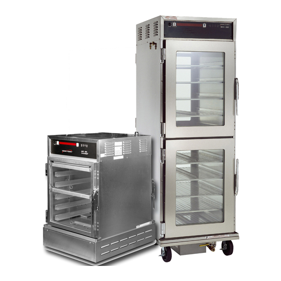
- Page 1 HUMIDIFIED HOLDING CABINET MODEL AHC-990 AHC-993 R E G I S T E R W A R R A N T Y O N L I N E AT W W W. H E N N Y P E N N Y. C O M...
-
Page 3: Table Of Contents
2-2. Unpacking ......................2-3. Location ........................ 2-4. Electrical Connection .................... 2-5. Water Capacity & Connections ................2-6. Water Quality Requirements ................. 2-7. Cabinet Dimensions and Weights ................. 2-8. AHC-993 Installation Guidelines ................. 2-9. AHC-990 Installation Guidelines ................. Section 3. OPERATION 3-1. Introduction ......................3-2. Operating Controls ....................3-3. Start-Up ......................... 3-4. Operation with Product ..................3-5. Cleaning Procedures ..................... -
Page 4: Section 1. Introduction
Model AHC-990/993 SECTION 1. INTRODUCTION 1-1. HUMIDIFIED The Henny Penny humidified holding cabinets are designed to HOLDING CABINET keep hot foods moist, while maintaining proper temperature. The units are electronically controlled for easy use and for consistent operation. As of August 16, 2005, the Waste Electrical and Electronic Equipment directive went into effect for the European Union. Our products have been evaluated to the WEEE directive. We have also reviewed our products to determine if they comply with the Restriction of Hazardous Substances directive (RoHS) and have redesigned our products as needed in order to comply. To continue compliance with these directives, this unit must not be disposed as unsorted municipal waste. For proper disposal, please contact your nearest Henny Penny distributor. 1-2. FEATURES • Electronically controlled humidity and temperature • Lift-off doors • Stainless steel construction • Easily maintained • Lift-out tray racks • Full perimeter magnetic door seals • Easy access to electrical controls • Automatic water tank fill 1-3. PROPER CARE As in any unit of food service equipment, the Henny Penny humidified holding cabinet does require care and maintenance. Requirements for the maintenance and cleaning are contained in this manual and must become a regular part of the operation of the unit at all times. -
Page 5: Safety
Model AHC-990/993 1-5. SAFETY The Henny Penny Humidified Holding Cabinet has safety features incorporated. However, to ensure a safe operation, read and fully understand the proper installation, operation, and maintenance procedures. The instructions in this manual have been prepared to aid you in learning the proper procedures. Where information is of particular importance or safety related, the words WARNING, CAUTION, and NOTICE are used. Their usage is described below. SAFETY ALERT SYMBOL is used with DANGER, WARNING, or CAUTION which indicates a personal injury type hazard. NOTICE is used to highlight especially important information. CAUTION used without the safety alert symbol indicates a potentially hazardous situation which, if not avoided, may result in property damage. CAUTION used with the safety alert symbol indicates a potentially hazardous situation which, if not avoided, may result in minor or moderate injury. -
Page 6: Section 2. Installation
Model AHC-990/993 SECTION 2. INSTALLATION 2-1. INTRODUCTION Installation of this unit should be performed only by a qualified service technician. Do not puncture the skin of the unit with drills or screws, or component damage or electrical shock could result. 2-2. UNPACKING The Henny Penny humidified holding cabinet has been tested, inspected, and expertly packed to ensure arrival at its destination in the best possible condition. Note any shipping damage in the presence of the delivery agent and signed prior to his or her departure. To remove the Henny Penny cabinet from carton: 1. Carefully cut banding straps. 2. Lift carton off the unit. -
Page 7: Location
Model AHC-990/993 2-2. UNPACKING 4. O pen doors and remove packing from behind racks and under (Continued) the water tank covers and remove the tape from the standpipe in the bottom of the unit. 5. P eel off all protective covering from the exterior of cabinet. 6. The cabinet is now ready for location and use. 2-3. LOCATION Place the humidified holding cabinet in an area that allows the doors to be opened without interference of loading and unloading product. Also, keep the unit level for proper operation. No minimum clearances are required for the rear and sides of the cabinet. 2-4. ELECTRICAL CONNECTION To avoid electrical shock, the cabinet must be adequately and safely grounded (earthed) according to local... -
Page 8: Water Capacity & Connections
Model AHC-990/993 2-4. ELECTRICAL AHC-990 CONNECTION Volts Hertz Phase Amps Watts (Continued) 24.0 2880 22.3 2680 50-60 13.2 2649 13.8 2880 50-60 12.0 2876 50-60 11.2 2676 220-240 50/60 11.6 2792 2-5. WATER CAPACITY & Applies to the AHC-993 & AHC-990 CONNECTIONS • Water Reservoir - 3 gal. (11.4 liters) capacity when in operation 2 gal. (7.6 liters) -
Page 9: Cabinet Dimensions And Weights
Humidified holding cabinet Model AHC-990/993 Automatic humidity control 2-7. CABINET DIMENSIONS AND WEIGHTS Externa (from b 38 in. (965 mm) Cold w connec auto fill 24 3/4 in. (628 mm) 31 3/4 in. (806 mm) AHC-993 Unit Height Width Depth... - Page 10 Model AHC-990/993 SmartHold holding cabinet ® 2-7. CABINET DIMENSIONS AND WEIGHTS (Continued) 72 1/4 in. (1835 mm) 24 3/4 in. (628 mm) 31 3/4 in. (806 mm) AHC-990 Dimensions Humidity: OFF/ON 10-90% RH Height: 72 1/4 in. (1835 mm) Unit...
-
Page 11: Ahc-993 Installation Guidelines
Model AHC-990/993 2-8. AHC-993 Due to the variations of equipment installations from one store INSTALLATION to another, we are providing only a general process which the GUIDELINES installer can use for reference or as a checklist. All electrical, water, and drain connections must comply with all federal, state, county, and local codes. 1. Unpack cabinet using paragraph 2-2 of this manual. 2. Position cabinet so controls face the store’s drive-thru area. When locating, moving, or positioning the holding cabinet, be careful not to scratch the table surface. 3. Remove 2 screws and bottom panel at front of unit. 4. Remove 2 screws and bottom panel at rear of unit. Steps 3 and 4 5. Measure and center unit front to rear on the table top with one side flush with the table end. Step 5 6. Using the holes in the cabinet base as guides, mark 4 mount- ing hole locations in the table top. Cabinet Base Holes (View from underneath cabinet) Marked Hole on Table Top ALL AHC-990 & AHC-993 units MUST have a water supply... - Page 12 Model AHC-990/993 2-8. AHC-993 INSTALLATION GUIDELINES (Continued) 3/4” 8. Layout routing of drain line from a 3/4” side outlet or 1” bot- tom outlet in drain block under unit to an open drain. 1” 9. Layout routing of electrical power cord from the top of the cabinet to the proper receptacle. Step 8 10. Measure, mark, and drill or cut holes or other openings in table top and/or shelves as dictated by this specific installa- tion to permit routing of water, drain, and electrical lines. 11. Fabricate the planned drain line. 12. Move unit to expose two marks at the front, center punch Steps 12 and 14 each mark, and drill 3/16” pilot holes. 13. Drill final holes using a 5/16” bit. Clean up all debris and metal shavings. 14. Shift cabinet position to expose two marks at the rear, center punch each mark, and drill 3/16” pilot holes. Steps 12 and 14 15. Drill final holes using a 5/16” bit. Clean up all debris and...
- Page 13 Model AHC-990/993 18. 993’s should have about 10” of clearance between 2-8. AHC-993 them to accommodate the packaging shelving tower (see INSTALLATION below). GUIDELINES (Continued) HP part no. 03559 Step 18 18. Perform a final positioning of the cabinet with one side flush with the table end and centered front to back on the table top. Tighten the fours bolts and nuts securely. 19. Apply a bead of clear silicone sealer around cabinet base to fill gaps between table top and base. 20. Connect water line and drain line to holding cabinet. Step 19 21. Connect electrical power to unit. 22. Operate holding cabinet and adjust water flow control valve so water does not overflow the fill tray and flood the cabinet. Acceptable flow is shown in photo at left. If necessary, the shut-off valve under the unit can be used to help regulate the water flow into the water pan. Normally, these should be opened fully. 23. Be sure fill tray angles down so water flows freely into pan. Step 22 24. Check cabinet for proper operation and repair any water leaks.
-
Page 14: Ahc-990 Installation Guidelines
Model AHC-990/993 2-9. AHC-990 Due to the variations of equipment installations from one store INSTALLATION to another, we are providing only a general process which the GUIDELINES installer can use for reference or as a checklist. All electrical, water, and drain connections must comply with all federal, state, county, and local codes. 1. Unpack cabinet using paragraph 2-2 of this manual. 2. Position cabinet so controls are accessible. 3. Locate the cold water fill line and drain is under the unit. See photo at left. Step 3 4. Layout routing of 1/4 inch fill line from the holding cabinet male quick disconnect under the unit to a cold water source. (Both male & female disconnects are supplied with the units) Step 4 5. Using an 1/8” to 1/4” reducer, a 1/4” x 6 ft. coiled hose (see below) can be attached to the female disconnect and the coiled hose is then connected to the in-coming water line. Step 5 Feb 2012... - Page 15 Model AHC-990/993 2-9. AHC-990 INSTALLATION GUIDELINES (Continued) 3/4” 6. Layout routing of drain line from a 3/4” side outlet or 1” bot- tom outlet in drain block under unit to an open drain. 1” Step 6 7. Several options are available for the AHC-990 drains: a. Install cabinet over floor drain for nightly draining. b. Disconnect water line and roll cabinet to nearest floor drain for nightly draining. c. Use the Henny Penny drain kit, part no. 03697 for nightly draining. See photo at left. 8. Connect water line to holding cabinet. Step 7 9. Connect electrical power to unit. 10. Operate holding cabinet and adjust water flow control valve so water does not overflow the fill tray and flood the cabinet. Acceptable flow is shown in photo at left. If necessary, the shut-off valve under the unit can be used to help regulate the water flow into the water pan. Normally, these should be opened fully. Step 10 11. Be sure fill tray angles down so water flows freely into pan.
-
Page 17: Section 3. Operation
Model AHC-990/993 SECTION 3. OPERATION 3-1. INTRODUCTION This section provides explanations of all controls, along with operating procedures and daily maintenance. Read the Introduction, Installation and Operation Sections before operating the unit. 3-2. OPERATING CONTROLS Fig. Item Description Function POWER Switch A rocker switch that sends electrical current to the operating components when turned on Temperature LED Lights when the control calls for heat, and the unit should start heating; it goes out once the temperature inside the cabinet reaches the programmed temperature setting Press the TEMPERATURE Button to set the cabinet temperature Digital Display Shows the cabinet temperature, humidity settings, and the selections in the Program Mode; the temperature of the cabinet is shown by pressing the INFO button; if the... - Page 18 Model AHC-990/993 3-2. OPERATING CONTROLS (Continued) Fig. Item Description Function Used to access the Program Modes; once in the Program Mode, it is used to advance to the next parameter; pressing this along with accesses the Information Mode which has historic information on the cabinet’s performance Control Decal Figure 3-1 Dec. 2011...
-
Page 19: Start-Up
Model AHC-990/993 3-3. START-UP Before using the humidified holding cabinet, thoroughly clean the unit as described in the Cleaning Procedures Section of this manual. 1. P lug unit into electrical receptacle, or turn on wall circuit breaker. With the POWER switch turned to OFF the display shows “POWER OFF.” With POWER Switch off, display may show “PURGING”. This means humidity has reached 95% inside unit and the fan runs to help drop the humidity. Once the humidity reaches 92%, “POWER OFF” again shows in the display. Even though POWER switch is OFF, it does not disconnect all electrical supplies to the controls. Unplug power cord, or turn off wall circuit breaker before servicing any electrical components, or electrical shock could result. -
Page 20: Operation With Product
Model AHC-990/993 3-4. OPERATION WITH 1. T he LEDs above the TEMPERATURE and HUMIDITY PRODUCT buttons go out when the desired temperature and humidity are reached inside the cabinet. Place hot product on pan. ATTENTION When using the AHC-990/993 Humidity Controlled Cabinets, The minimum holding temperature for potentially hazardous all Original Recipe products product is 150° F (66° C). Also, the cabinet product load must use a new Milk and Egg capacity for the half size unit is 125 lb. (57 kg.). View the packet (GIN 27414) instead of temperature at any time by pressing the current Milk and Egg (GIN 2. Slide pans with hot product onto the racks of the cabinet. 20131). Standard hold times must be observed if you are not using the If float switch in water pan senses low, or no water after 5 new Milk and Egg packet. minutes, “WATER PAN NOT FILLING, CHECK WATER SUPPLY” shows in display. Check water fill system. 3. O pen doors only as needed to load and unload product. This helps to keep interior conditions constant and saves energy. 3-5. CLEANING Daily: PROCEDURES 1. Turn controls and water off and disconnect electrical supply. - Page 21 Model AHC-990/993 3-5. CLEANING 6. W ipe the control panel with a damp cloth. Do not splash water PROCEDURES around controls. (Continued) 7. R einstall standpipe, concentration ring, water pan covers, racks, and leave a door partially open over night to allow interior cabinet to thoroughly dry. Weekly: 1. Turn off controls & water and remove pans and racks from cabinet. 2. A llow unit and water to cool, then pull stand pipe out of drain hole to empty water pan. See Figure 3-3. Figure 3-4 Stand pipe could be hot! Allow to cool before removing or burns could result.
- Page 22 Model AHC-990/993 3-5. CLEANING PROCEDURES (Continued) Monthly: 1. R emove the 2 screws securing the vented panel on the rear of the module, remove the panel, and clean vents. See Figure 3-5. Figure 3-5 2. U sing a cloth or sponge, clean the trough once a month. To avoid damage to the gasket, wipe clean daily 1. Allow unit to cool. Open the doors. 2. Using a damp towel, wipe gaskets and door. Be sure that both gaskets and doors are free of grease build up. Feb. 2013...
-
Page 23: Section 4. Programming
Model AHC-990/993 SECTION 4. PROGRAMMING 4-1. INTRODUCTION This section explains the following programming functions. • Clock-set • Special programming 4-2. “HIDDEN BUTTONS” To program the following features, 5 hidden buttons must be pressed. 4-3. CLOCK SET Press and hold for a few seconds until “L-2 (Time-of-day, date, and day of the week) LEVEL 2” followed by “CLOCK SET” shows in display. After 5 seconds, “ENTER CODE” shows in display. Press hidden buttons . See Section 4-2. A total of 5 hidden buttons exist. If the wrong code is pressed, “INVALID CODE” scrolls across the display, and controls automatically exit the Program Mode. “CS-1, SET, HOUR”, and the time of day (with the hour flashing) shows in the display. Press the to change the hours. Dec. 2011... - Page 24 Model AHC-990/993 4-3. CLOCK SET Press and “CS-2, SET, MINUTE” shows in the (Continued) display, with the minutes flashing. Press to change the minutes. Press and “CS-3, SET, MONTH” shows in the display, along with the date (month flashing). Press to change the month. 10. Press and “CS-4, SET, DATE” shows in the display, with the date flashing. 11. Press to change the date. 12. Press and “CS-5, SET, YEAR” shows in the display, with the year flashing. 13. Press to change the year. 14. Press and hold to exit programming. Dec. 2010...
-
Page 25: Special Programming
Model AHC-990/993 4-4. SPECIAL PROGRAMMING This mode allows you to program the following: SP-1 • Fahrenheit/Celsius SP-2 • Lock/unlock SP-3 • Air temperature setpoint SP-4 • Humidity setpoint or Off SP-5 • Out of water trip point SP-6 • System intialization SP-7 • Audio volume SP-8 • Audio tone SP-9 • Audio effects SP-10 • Language options SP-11 • CE heat regulation SP-12 • Water fill option SP-1 Fahrenheit/Celsius 1. Press and hold... - Page 26 Model AHC-990/993 4-4. SPECIAL PROGRAMMING (Continued) SP-3 Air Temperature Setpoint 9. Press and “SP-3, AIR TEMP SET POINT,” and the preset cabinet temperature shows in display. 10. Press to change the air temperature setpoint, F (60 C) minimum, 210 F (99 C) maximum. SP-4 Humidity Setpoint 11. Press and “SP-4, HUMIDITY SET POINT,” and the preset humidity setpoint shows in display. 12. Press to change the humidity setpoint from 10% to 90% or to turn the humidity system to OFF. SP-5 Out of Water Trip Point 13. Press and “SP-5, MAX WATER HTR SET POINT” or the preset trip point temperature shows in display. If float...
- Page 27 Model AHC-990/993 4-4. SPECIAL PROGRAMMING (Continued) SP-8 Audio Tone 19. Press and “SP-8, AUDIO TONE -(Hz)-” and the tone setting (50 to 2000) shows in display. 20. Press to change the tone setting. SP-9 Audio Effects 21. Press and “SP-9, AUDIO EFFECT” and the effect setting (0 to 3) shows in display. 22. Press to change the pattern of the tone. SP-10 Language Options 23. Press and “SP-10, LANGUAGE,” and the preset language shows in the display. 24. Press to change to English, French, German, Spanish, or Portuguese. SP-11 CE Heat Regulation 25. Press and “SP-11, CE HEAT REG.” and “NO” or...
- Page 28 Model AHC-990/993 SP-12 Water Fill Option 27. Press and “SP-12, WATER FILL OPTION” and “AUTO” or “MANUAL”shows in the display. 28. Press and select “AUTO” if unit has automatic water fill ability, or manual, if water pan has to be manually filled. 29. Press and hold button anytime during programming to exit the Special Programming Mode. For more information on the other settings of Special Programming, call your local Henny Penny distributor in your area, or call Henny Penny Corp. at 1-800-417-8405 or 1-937-456-8405. Dec. 2010...
-
Page 29: Section 5. Troubleshooting
Model AHC-990/993 SECTION 5. TROUBLESHOOTING 5-1. TROUBLESHOOTING GUIDE PROBLEM CAUSE CORRECTION Product not holding • D oors left open • K eep doors closed except to load and temperature serve product • P roduct held too long • H old product only for recommended times • C ontrol temperature set too • I ncrease air temperature (SP-3) in Special Program Mode • A HC-990 door gasket torn • R eplace bad door gaskets... -
Page 30: Error Codes And Warnings
Model AHC-990/993 5-2. ERROR CODES AND The display shows the following error codes and warnings when WARNINGS a fault is detected, along with an alarm sound. Both the heat and humidity systems shut down, except when specified otherwise. Display Cause Panel Board Correction “E-4 C PU TOO HOT” • C ontrol board too hot; unit • T urn switch to OFF position, then overheating or louvers back to ON; if display still shows “E- clogged 4”, the PC board is getting too hot; clean louvers and check cooling fan; if cooling fan is not working, have it replaced; once panel cools down, the controls should return to normal; if “E- 4” persists, have the PC board replaced “E-5 A IR TEMP TOO • F aulty relay, PC board, or • T urn switch to OFF position, then back HOT”... - Page 31 Model AHC-990/993 5-2. ERROR CODES AND WARNINGS (Continued) Display Cause Panel Board Correction “E-6B A IR TEMP • F aulty air temperature probe • T urn switch to OFF position, then back to ON; SENSOR if the display shows “E-6”, the temperature FAILED probe should be checked; once the temperature SHORTED” probe is repaired, or replaced, the controls should return to normal; if “E-6”persists, have PC board replaced “E-12A WATER • F aulty water heater probe • T urn switch to OFF position, then back to HEATER ON; if the display shows “E-12A”, the water...
- Page 32 Model AHC-990/993 5-2. ERROR CODES AND WARNINGS (Continued) Display Cause Panel Board Correction “E-46 DATA SAVE • M emory scrambled • T urn switch to OFF position, then back FAILED” to ON; if the display shows “E-46”, the control should be re-initialized (see Programming Section); if “E-46”persists, have PC board replaced “E-80 V ENT STUCK • V ent on rear of module • C heck vent on rear of module for OR BAD stuck or faulty vent obstructions, or have vent activation SWITCH”...
- Page 33 Henny Penny Corporation P.O.Box 60 Eaton,OH 45320 1-937-456-8400 1-937-456-8402 Fax Toll free in USA 1-800-417-8417 1-800-417-8434 Fax www.hennypenny.com *FM05-063-H* 11-10-14 Henny Penny Corp., Eaton, Ohio 45320, Revise...