Table of Contents
Advertisement
Quick Links
AIRCRAFT MAINTENANCE
MANUAL
SINGLE COCKPIT AND DUAL COCKPIT
Model S2R – G10
Serial Numbers S2R-G10 S/N G10-169 & up
Issued March 26, 2010
Note:
All serial numbers with the DC suffix indicate the dual cockpit configuration.
Manufacturer's Serial Number: ____________
Registration Number: ________________
Thrush Aircraft
Inc.
P. O. Box 3149
300 Old Pretoria Road
Albany, GA 31706
Telephone: 229-883-1440
Fax: 229-436-4856
i
Effective: 03/26/2010
page
Advertisement
Chapters
Table of Contents
Troubleshooting

Related Manuals for THRUSH S2R – G10


Summary of Contents for THRUSH S2R – G10
-
Page 1: Aircraft Maintenance
Issued March 26, 2010 Note: All serial numbers with the DC suffix indicate the dual cockpit configuration. Manufacturer’s Serial Number: ____________ Registration Number: ________________ Thrush Aircraft Inc. P. O. Box 3149 300 Old Pretoria Road Albany, GA 31706 Telephone: 229-883-1440... - Page 2 All information contained in this manual is based on the latest product information available at the time of printing. Thrush Aircraft, Inc. reserves the right to make changes at any time without notice.
- Page 3 THRUSH AIRCRAFT INC. – MODEL S2R-R1340 AIRCRAFT MAINTENANCE MANUAL Manual Organization This maintenance manual is divided into the following eleven sections, each with its own table of contents: SECTION 1..........GENERAL INFORMATION SECTION 2..........SERVICING & INSPECTION SECTION 3..........HYDRAULICS SECTION 4..........
- Page 4 THRUSH AIRCRAFT INC. – MODEL S2R-R1340 AIRCRAFT MAINTENANCE MANUAL SECTION 2 LOG OF PAGES SERVICING & INSPECTION INTRODUCTION (Continued) Page Date Page Date ........03/26/2010 ........03/26/2010 ........03/26/2010 ........03/26/2010 ........03/26/2010 ........03/26/2010 ........03/26/2010 ........03/26/2010 ........
- Page 5 THRUSH AIRCRAFT INC. – MODEL S2R-R1340 AIRCRAFT MAINTENANCE MANUAL SECTION 5 SECTION 7 FUEL SYSTEM FLIGHT continued CONTROLS Page Date continued ........03/26/2010 Page Date ........03/26/2010 ........03/26/2010 ........03/26/2010 ........03/26/2010 ........03/26/2010 ........03/26/2010 ........03/26/2010 ........
- Page 6 THRUSH AIRCRAFT INC. – MODEL S2R-R1340 AIRCRAFT MAINTENANCE MANUAL SECTION 9 SECTION 11 DISPERSAL AIRWORTHINESS SYSTEMS LIMITATIONS Page Date Page Date ........03/26/2010 ........03/26/2010 ........03/26/2010 ........03/26/2010 ........03/26/2010 ........03/26/2010 ........03/26/2010 ........03/26/2010 ........03/26/2010 BLANK...
- Page 8 THRUSH AIRCRAFT INC. – MODEL S2R-R1340 AIRCRAFT MAINTENANCE MANUAL THIS PAGE INTENTIONALLY LEFT BLANK viii page Effective: 03/26/2010...
-
Page 9: Table Of Contents
THRUSH AIRCRAFT, INC – MODEL S2R-G10 AIRCRAFT MAINTENANCE MANUAL SECTION 1 GENERAL INFORMATION TABLE OF CONTENTS GENERAL DESCRIPTION ....................2 CONTACT INFORMATION ..................2 PRINCIPAL DIMENSIONS ....................2 GENERAL........................2 WEIGHT & BALANCE ....................2 WING ..........................2 HORIZONTAL STABILIZER AND ELEVATORS ............3 VERTICAL STABILIZER AND RUDDER .............. -
Page 10: General Description
AIRCRAFT MAINTENANCE MANUAL GENERAL DESCRIPTION The Thrush Aircraft Inc Thrush S2R-G10 is designed especially for agricultural flying. It is a monoplane featuring a full cantilever low wing and all metal construction. The design and construction of the airframe components assure structural integrity, flight safety, and minimum maintenance requirements. -
Page 11: Horizontal Stabilizer And Elevators
THRUSH AIRCRAFT, INC – MODEL S2R-G10 AIRCRAFT MAINTENANCE MANUAL HORIZONTAL STABILIZER AND ELEVATORS Span..........204 Inches (17') Elevator Travel Up........27 Degrees ±1 Degree Down ........17 Degrees ±1 Degree Trim Tab Travel Up........8 Degrees ±1 Degree Down ........ -
Page 12: Aircraft Structure
THRUSH AIRCRAFT, INC – MODEL S2R-G10 AIRCRAFT MAINTENANCE MANUAL universal rivets for strength. The fuel AIRCRAFT STRUCTURE tanks, which are located in the inboard FUSELAGE section of the wing, are an integral part of the structure. Close pitch riveting of the... -
Page 13: Aircraft Systems
POWER PLANT & PROPELLER positive pressure on the fuel tanks. The The Thrush S2R-G10 is powered by the vent system is provided with two quick Garrett (Honeywell) TPE331-10 turbo-prop drains, located on the fuselage under each engine. -
Page 14: Landing Gear, Wheels & Brakes
THRUSH AIRCRAFT, INC – MODEL S2R-G10 AIRCRAFT MAINTENANCE MANUAL impurities and water accumulation from the operation. The aileron and elevator bulk fuel. If filtering facilities are not controls are push rod systems and rudder available, filter the fuel through a quality control is through tension cables. -
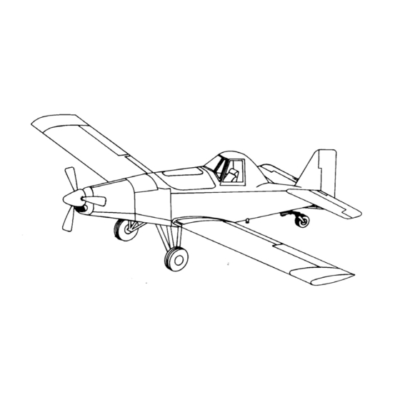
Page 15: Figure 1-1: Aircraft 3-View
THRUSH AIRCRAFT, INC – MODEL S2R-G10 AIRCRAFT MAINTENANCE MANUAL Figure 1-1: Aircraft 3-view Effective: 03/26/2010 page... -
Page 16: Figure 1-2: Aircraft Stations
THRUSH AIRCRAFT, INC – MODEL S2R-G10 AIRCRAFT MAINTENANCE MANUAL Figure 1-2: Aircraft Stations page Effective: 03/26/2010... - Page 17 THRUSH AIRCRAFT, INC – MODEL S2R-G10 AIRCRAFT MAINTENANCE MANUAL Effective: 03/26/2010 page...
- Page 18 THRUSH AIRCRAFT, INC – MODEL S2R-G10 AIRCRAFT MAINTENANCE MANUAL SECTION 2 SERVICING & INSPECTION TABLE OF CONTENTS SERVICING & INSPECTION ..................3 GENERAL DESCRIPTION GROUND HANDLING ....................3 TOWING....................... 3 TAXIING ....................... 3 PARKING ......................3 MOORING ......................3 JACKING ......................3 LEVELING ......................
- Page 19 THRUSH AIRCRAFT, INC – MODEL S2R-G10 AIRCRAFT MAINTENANCE MANUAL Table 2-2: INSPECTION CHECK LIST ............14 A: Propeller ....................13 B: Engine Externals ..................15 C: Engine Oil System..................16 D: Engine Fuel Xystem ................. 17 E: IGNITION SYSTEM .................. 17 F: Airframe Fuel System ................
-
Page 20: Servicing & Inspection
THRUSH AIRCRAFT, INC – MODEL S2R-G10 AIRCRAFT MAINTENANCE MANUAL PARKING SERVICING & INSPECTION Head the aircraft into the wind and set the Standard procedure for ground handling, parking brake. Do not set the parking servicing, inspection, airframe brake during cold wet weather because the... - Page 21 THRUSH AIRCRAFT, INC – MODEL S2R-G10 AIRCRAFT MAINTENANCE MANUAL Figure 2-1: Leveling, Tie Down and Jack Points Page Effective 03/26/2010...
-
Page 22: Weighing
THRUSH AIRCRAFT, INC – MODEL S2R-G10 AIRCRAFT MAINTENANCE MANUAL WEIGHING C.G. of equipment = -23.5 (ie. forward of wing leading edge) Calculated Weight Moment change = 17 x (-23.5) = The weight and center of gravity (C.G.) of - 400 in.#... -
Page 23: Cold Weather Operation
THRUSH AIRCRAFT, INC – MODEL S2R-G10 AIRCRAFT MAINTENANCE MANUAL weight C.G. is the total moment divided by COLD WEATHER the total weight. MAINTENANCE HINTS For example: The information that follows is intended Left MLG scale reading = 2,127# only for the purpose of supplementing the... -
Page 24: Ground Emergency Procedures
THRUSH AIRCRAFT, INC – MODEL S2R-G10 AIRCRAFT MAINTENANCE MANUAL not available, tie the aircraft down and weather from the wing, the tail, and the install covers on all vents, openings, etc. control surfaces. Check that the control as required. surfaces contain no internal accumulations of ice. -
Page 25: Starting Engine
THRUSH AIRCRAFT, INC – MODEL S2R-G10 AIRCRAFT MAINTENANCE MANUAL f. Turn Battery Switch ON, or to EXT To accomplish the check, do the following PWR position if external power will be during starting: used to start the engine. 1) NTS Light – PRESS to test 2) Unfeathering Pump Switch –... -
Page 26: System And Component Servicing
THRUSH AIRCRAFT, INC – MODEL S2R-G10 AIRCRAFT MAINTENANCE MANUAL m. Engine Instruments – CHECK Reference Section 4 The oils that are specified for the 1) RPM – 72% Minimum lubrication system can be found in the 2) Fuel Pressure – 8 PSIG Minimum applicable engine Maintenance Manual. -
Page 27: Fuel System
THRUSH AIRCRAFT, INC – MODEL S2R-G10 AIRCRAFT MAINTENANCE MANUAL If the oil level is too low to register on the must be conducted with the electrical fuel dipstick possible excessive auxiliary boost pump ON. consumption or if low or fluctuating oil... - Page 28 THRUSH AIRCRAFT, INC – MODEL S2R-G10 AIRCRAFT MAINTENANCE MANUAL All fuel drains should be drained prior to the finger strainers annually or if the fuel first flight of the day. Drain a small quantity of system is thought to have been or is...
-
Page 29: Defueling
THRUSH AIRCRAFT, INC – MODEL S2R-G10 AIRCRAFT MAINTENANCE MANUAL fuel containers a safe distance from WARNING the aircraft. d. Verify that all the drain valves are IF THE RED FUEL BYPASS closed. INDICATOR BUTTON LANDING GEAR, WHEELS & POPPED OUT, INVESTIGATE... -
Page 30: Brake Bleeding
THRUSH AIRCRAFT, INC – MODEL S2R-G10 AIRCRAFT MAINTENANCE MANUAL BRAKE BLEEDING d. Wiring is to be checked for security, chafing, burning, defective insulation, Brake bleeding should be performed when and loose or broken terminals, heat air is suspected of being entrapped in deterioration, and corroded terminals. -
Page 31: A: Propeller
THRUSH AIRCRAFT, INC – MODEL S2RHG-T65 TURBO THRUSH AIRCRAFT MAINTENANCE MANUAL Figure 2-3: G10 Servicing and Inspection Guide Table 2-2: INSPECTION CHECK LIST A: PROPELLER Refer to Hartzell Manual #139 Propeller Owner’s Manual and Logbook or Appropriate McCauley Maintenance Manual. -
Page 32: B: Engine Externals
THRUSH AIRCRAFT, INC – MODEL S2R-G10 AIRCRAFT MAINTENANCE MANUAL B: ENGINE EXTERNALS Refer to appropriate Garrett Maintenance Manual for Pertinent Details on Engine Inspection. Periodic Engine Inspection and Servicing should be followed in accordance with the engine Periodic Inspection Requirements Table in the engines’... -
Page 33: C: Engine Oil System
Check condition and security of oil filler cap. Oil Filter – Remove, inspect and replace paper oil filter element. * NOTE * Thrush Aircraft, Inc. highly recommends utilizing a S.O.A.P. (Spectrometric Oil Analysis Program). A S.O.A.P. kit includes: 1) New filter element “O” ring (if required), oil sample kit, filter bottle and return packaging. - Page 34 THRUSH AIRCRAFT, INC – MODEL S2R-G10 AIRCRAFT MAINTENANCE MANUAL C: ENGINE OIL SYSTEM (Continued) Check the chip detector for continuity using a suitable ohmmeter. An open circuit condition, which indicates no ferrous contamination at pole tips, must exist. Inspect oil cooler for damage, cleanliness, leaks, and security.
- Page 35 THRUSH AIRCRAFT, INC – MODEL S2R-G10 AIRCRAFT MAINTENANCE MANUAL F. AIRFRAME FUEL SYSTEM Remove, inspect, clean, and re-install the airframe main 25-micron fuel strainer. * NOTE * On new aircraft, check the firewall fuel filter after each flight until there is no evidence of contamination.
-
Page 36: G: Main Landing Gear
THRUSH AIRCRAFT, INC – MODEL S2R-G10 AIRCRAFT MAINTENANCE MANUAL G: MAIN LANDING GEAR Check the main landing gear attach-fittings and pivot bolts. Replace bolts if worn. Check the tires and tubes, wheels, and brake discs and lining for general condition. - Page 37 THRUSH AIRCRAFT, INC – MODEL S2R-G10 AIRCRAFT MAINTENANCE MANUAL J: TAIL GEAR (Continued) Inspect tailwheel leaf spring for corrosion and cracks. Replace leaf spring as needed. Inspect all bolt holes for elongation. As a general rule, replace components with holes that are out- of-round by 0.005”...
-
Page 38: K: Fuselage Skins
THRUSH AIRCRAFT, INC – MODEL S2R-G10 AIRCRAFT MAINTENANCE MANUAL J: TAIL GEAR (Continued) Check the taper bearings spindle and spline-shaft for corrosion and wear. Grease bearings with MIL-G-81322 (Aeroshell grease before reassembling wheel. Check the centering springs for corrosion, attachment security and correct operation. -
Page 39: N: Fuselage Frame
THRUSH AIRCRAFT, INC – MODEL S2R-G10 AIRCRAFT MAINTENANCE MANUAL M: WINGS (Continued) Check the boots at the aileron push rod entrance to the wing root for condition and security. Check for deposits of chemicals around and behind the wing center section and all attachment fittings. -
Page 40: P: Control Systems
THRUSH AIRCRAFT, INC – MODEL S2R-G10 AIRCRAFT MAINTENANCE MANUAL N: FUSELAGE (Continued) Inspect main landing gear attachment fittings, shock strut attach fittings and tail gear trunnion fittings for security, cracks, and corrosion. Check the condition of the paint and refinish, if necessary. -
Page 41: Q: Empennage
THRUSH AIRCRAFT, INC – MODEL S2R-G10 AIRCRAFT MAINTENANCE MANUAL P: CONTROL SYSTEMS (Continued) Remove control stick from main the torque tube. Inspect bolt and bearings and replace as required. Hours Q: EMPENNAGE Check the travel of the movable surfaces. Elevator up ...... 27 degrees ±1 degree Elevator down.... -
Page 42: S: Cockpit
THRUSH AIRCRAFT, INC – MODEL S2R-G10 AIRCRAFT MAINTENANCE MANUAL R: AILERONS AND FLAPS (Continued) Aileron servo tabs a. Check security of hinges b. Check for looseness of rod ends and bolts. c. Check for freedom of travel. d. Lubricate hinges. -
Page 43: T: Electrical System
THRUSH AIRCRAFT, INC – MODEL S2R-G10 AIRCRAFT MAINTENANCE MANUAL S: COCKPIT (Continued) Check operation of flight & engine controls to ensure proper operation and installation. T: ELECTRICAL SYSTEM Check the battery charge and water level. Check battery relays, spike diodes, regulator, fuses, and switches for security. - Page 44 THRUSH AIRCRAFT, INC – MODEL S2R-G10 AIRCRAFT MAINTENANCE MANUAL aircraft exterior and interior is highly water unless close attention is made to recommended. During the working season avoid removal of lubricants and to cleaning intervals should never be more avoid possible rusting of components than a week.
-
Page 45: Windshield
THRUSH AIRCRAFT, INC – MODEL S2R-G10 AIRCRAFT MAINTENANCE MANUAL coat directly onto the primed surfaces. and carefully buff out with a soft cloth. Do Apply at least two coats and allow time not buff or polish in one area for more than for drying between the coats. - Page 46 THRUSH AIRCRAFT, INC – MODEL S2R-G10 AIRCRAFT MAINTENANCE MANUAL Table 2-3: TORQUE CHART BOLTS BOLTS FINE THREAD STEEL - TENSION STEEL - TENSION STEEL - SHEAR STEEL SERIES AN 3 thru AN 20 MS 20004 thru MS 20024 NAS 333 - NAS 340...
-
Page 47: Lubrication
THRUSH AIRCRAFT, INC – MODEL S2R-G10 AIRCRAFT MAINTENANCE MANUAL LUBRICATION For the lubrication requirements, refer to Figure 2-4: Lubrication Chart (9 sheets). Before adding grease to fittings, wipe the fittings clean. Lubricate the fittings and wipe off the excess lubricant. Lubricate the hinges with a squirt can or a brush moistened with oil. Wipe off the excess oil to prevent accumulation of dirt and grit. - Page 48 THRUSH AIRCRAFT, INC – MODEL S2R-G10 AIRCRAFT MAINTENANCE MANUAL Figure 2-4: Lubrication Chart (sht. 2 of 9) 2-31 Effective: 03/26/2010 Page...
- Page 49 THRUSH AIRCRAFT, INC – MODEL S2R-G10 AIRCRAFT MAINTENANCE MANUAL Figure 2-4: Lubrication Chart (sht. 3 of 9) 2-32 Page Effective 03/26/2010...
- Page 50 THRUSH AIRCRAFT, INC – MODEL S2R-G10 AIRCRAFT MAINTENANCE MANUAL Figure 2-4: Lubrication Chart (sht. 4 of 9) 2-33 Effective: 03/26/2010 Page...
- Page 51 THRUSH AIRCRAFT, INC – MODEL S2R-G10 AIRCRAFT MAINTENANCE MANUAL Figure 2-4: Lubrication Chart (sht. 5 of 9) 2-34 Page Effective 03/26/2010...
- Page 52 THRUSH AIRCRAFT, INC – MODEL S2R-G10 AIRCRAFT MAINTENANCE MANUAL Figure 2-4: Lubrication Chart (sht. 6 of 9) 2-35 Effective: 03/26/2010 Page...
- Page 53 THRUSH AIRCRAFT, INC – MODEL S2R-G10 AIRCRAFT MAINTENANCE MANUAL Figure 2-4: Lubrication Chart (sht. 7 of 9) Figure 2-4: Lubrication Chart (sht. 8 of 9) 2-36 Page Effective 03/26/2010...
- Page 54 THRUSH AIRCRAFT, INC – MODEL S2R-G10 AIRCRAFT MAINTENANCE MANUAL Figure 2-4: Lubrication Chart (sht. 9 of 9) 2-37 Effective: 03/26/2010 Page...
- Page 55 THRUSH AIRCRAFT, INC – MODEL S2R-G10 AIRCRAFT MAINTENANCE MANUAL THIS PAGE INTENTIONALLY LEFT BLANK 2-38 Page Effective 03/26/2010...
- Page 56 THRUSH AIRCRAFT, INC – MODEL S2R-G10 AIRCRAFT MAINTENANCE MANUAL SECTION 3 HYDRAULICS TABLE OF CONTENTS HYDRAULIC SYSTEM..................2 GENERAL DESCRIPTION................2 MASTER CYLINDER .................. 2 Figure 3-1: Brake Master Cylinder............2 Figure 3-2: Brake Master Cylinder and Rudder Pedal Installation ..3 BRAKE SYSTEM BLEEDING ..............
-
Page 57: Hydraulic System
THRUSH AIRCRAFT, INC – MODEL S2R-G10 AIRCRAFT MAINTENANCE MANUAL pressure on the pedals. As toe pressure is applied to the pedals, a push rod and belcrank linkage moves an actuator rod, HYDRAULIC SYSTEM pushing a piston in the master brake cylinder. - Page 58 THRUSH AIRCRAFT, INC – MODEL S2R-G10 AIRCRAFT MAINTENANCE MANUAL The master cylinder piston is actuated by the push rod, which is in turn actuated by a Hydraulic fluid reservoirs should be kept at mechanical linkage to the rudder pedal least half full.
-
Page 59: Brake System Bleeding
THRUSH AIRCRAFT, INC – MODEL S2R-G10 AIRCRAFT MAINTENANCE MANUAL ID clear plastic tubing, clean rags and BRAKE SYSTEM BLEEDING extra MIL-H-5606 hydraulic fluid. Ref. Fig. 3-3 3. Put the clear plastic tubing on one of the bleeder valves at the bottom of the weak “spongy”... - Page 60 THRUSH AIRCRAFT, INC – MODEL S2R-G10 AIRCRAFT MAINTENANCE MANUAL 6. Close the bleeder valve and place the master cylinder hydraulic reservoir. plastic tube on the other bleeder valve. 9. Dispose of the hydraulic fluid bled into 7. Bleed that caliper the same as above.
-
Page 61: Parking Brakes
THRUSH AIRCRAFT, INC – MODEL S2R-G10 AIRCRAFT MAINTENANCE MANUAL An alternative method of bleeding the PARKING BRAKES brakes is as follows: Ref. Fig. 3-2 1. Place a large clean container under the Parking brakes are actuated by depressing master brake cylinder and uncap the the brake pedals as normal and then hydraulic fluid reservoir. - Page 62 THRUSH AIRCRAFT INC - MODEL S2R-G10 AIRPLANE MAINTENANCE MANUAL SECTION 4 POWER PLANT AND PROPELLER TABLE OF CONTENTS POWER PLANT ........................2 AIR CLEANING SYSTEM ............................2 ENGINE BUILDUP ...............................2 OIL CONTAMINATION ............................2 ENGINE REMOVAL .............................2 ENGINE INSTALLATION .............................3 PROPELLER........................4 PROPELLER DESCRIPTION AND OPERATION....................5...
-
Page 63: Power Plant
THRUSH AIRCRAFT INC - MODEL S2R-G10 AIRPLANE MAINTENANCE MANUAL cleaning. Failure to comply with the above POWER PLANT procedure will prove to be false economy, as the new engine will be contaminated by The Garrett TPE-331 powered Turbo old impurities. -
Page 64: Engine Installation
THRUSH AIRCRAFT INC - MODEL S2R-G10 AIRPLANE MAINTENANCE MANUAL * NOTE * Tag and identify all tube and hose * NOTE * assemblies to facilitate and ensure It is not necessary to remove correct installation of the engine. engine control belcrank assembly... -
Page 65: Propeller
THRUSH AIRCRAFT INC - MODEL S2R-G10 AIRPLANE MAINTENANCE MANUAL mounts. Install the attaching 10. Fuel valve hardware. Torque the three 11. Ignition exciter box forward bolts to 480-600 inch- 12. Starter/generator pounds and the rear bolt at 25 inch-pounds. Install all cotter 13. -
Page 66: Propeller Description And Operation
THRUSH AIRCRAFT INC - MODEL S2R-G10 AIRPLANE MAINTENANCE MANUAL PROPELLER DESCRIPTION AND speed operation, starting, stopping and ground run-up is consistent with standard OPERATION practice for this type propeller. The propeller is a single-acting unit in In-flight loss of oil pressure, whether due to... -
Page 67: Propeller Installation - Mccauley
THRUSH AIRCRAFT INC - MODEL S2R-G10 AIRPLANE MAINTENANCE MANUAL Mark propeller hub flange and the measurements at the blade station given in engine shaft flange so that the the propeller owner’s manual, or Figure 4- propeller can be reinstalled in its original position. - Page 68 THRUSH AIRCRAFT INC - MODEL S2R-G10 AIRPLANE MAINTENANCE MANUAL PROPELLER Hartzell 4- McCauley 4- McCauley 4- blade blade blade HCB4TN-5NL- 4HFR34C653-[X] 4HFR34C662-[X] Model Number LT10890N [X]-L106FA-0 [X]-L108FA-0 Used On Engine Type TPE331-10 TPE331-10 TPE331-10 Diameter (inches) max. 109.5 106.0 108.0 Diameter (inches) min.
-
Page 69: Spinner Installation - Mccauley - Ref. Fig
THRUSH AIRCRAFT INC - MODEL S2R-G10 AIRPLANE MAINTENANCE MANUAL Count the turns, beginning with the first Install shims and spinner support on thread engages. 35 full turns is equivalent propeller cylinder. Lightly press shell snug to approximately 12 degrees of flight idle against support and check alignment of blade angle. -
Page 70: Propeller Installation - Hartzell
THRUSH AIRCRAFT INC - MODEL S2R-G10 AIRPLANE MAINTENANCE MANUAL latest upgrade) antiseize compound to mounting bolt threads and washer * NOTE * surfaces (and remainder of bolts if Mark propeller hub flange and the desired). For the HC-B4TN-5NL engine shaft flange so that the... - Page 71 THRUSH AIRCRAFT INC - MODEL S2R-G10 AIRPLANE MAINTENANCE MANUAL the prop blade is parallel with the horizon the blade angle. and the aircraft wings are generally level. Checking and adjusting the flight idle blade Zero the propeller protractor on the...
-
Page 72: Spinner Installation - Hartzell
THRUSH AIRCRAFT INC - MODEL S2R-G10 AIRPLANE MAINTENANCE MANUAL after the engine has been run and is still RIGGING AIRFRAME ENGINE hot. CONTROLS SPINNER INSTALLATION – Engine speed and propeller function is Hartzell controlled through connecting assemblies, belcrank assemblies, cables Install spinner, aligning marks if replacing and cockpit quadrant levers. -
Page 73: Rigging Instructions
THRUSH AIRCRAFT INC - MODEL S2R-G10 AIRPLANE MAINTENANCE MANUAL RIGGING INSTRUCTIONS c. Positioning the 21712-1 control shaft assembly on the airframe: a. Rigging the throttle quadrant to the Refer this control cables: Ref. Fig. 4-3 dimension. With clevis forks (2 places) not yet d. -
Page 74: Rigging Fuel Cutoff And Feather
THRUSH AIRCRAFT INC - MODEL S2R-G10 AIRPLANE MAINTENANCE MANUAL RIGGING FUEL CUTOFF AND FEATHER (DETENT) position, go back to the engine. Ref. Fig. 4-5 & Fig. 4-6 h. Manually rotate the fuel cutoff/feather a. At the fuel shutoff valve, (Fig 4-5) belcrank to the feather position. -
Page 75: Throttle Rigging
THRUSH AIRCRAFT INC - MODEL S2R-G10 AIRPLANE MAINTENANCE MANUAL the middle hole. Figure 4-6: e. Remove the rigging pin and move the THROTTLE RIGGING: power lever to full throttle position. The Ref. Fig. 4-6 pointer should move to 100 degrees and stop out with a minimum of 1/8 a. -
Page 76: Speed Lever Rigging
THRUSH AIRCRAFT INC - MODEL S2R-G10 AIRPLANE MAINTENANCE MANUAL flight testing. to positively clear the vertical peg on the serrated arm. The under speed SPEED LEVER RIGGING: governor should be on the minimum Ref. (Fig. 4-7) stop. a. Set the 21712-61 underspeed governor... -
Page 77: Ground Idle Adjustments
THRUSH AIRCRAFT INC - MODEL S2R-G10 AIRPLANE MAINTENANCE MANUAL full regime of performance checks required decelerates rapidly and the propeller for proper engine operation and continued feathers immediately. Watch for an airworthiness of the aircraft. immediate EGT decrease. If not, stop... - Page 78 THRUSH AIRCRAFT INC - MODEL S2R-G10 AIRPLANE MAINTENANCE MANUAL On the torque pressure indicator, change the position of the red “bug” to correspond with the pressure value determined above and secure in place with a sealing compound. On the instrument panel...
- Page 79 THRUSH AIRCRAFT INC - MODEL S2R-G10 AIRPLANE MAINTENANCE MANUAL THIS PAGE INTENTIONALLY LEFT BLANK 4-18 Page Effective: 03/26/2010...
- Page 80 THRUSH AIRCRAFT, INC – MODEL S2R G10 AIRCRAFT MAINTENANCE MANUAL SECTION 5 FUEL SYSTEM TABLE OF CONTENTS GENERAL DESCRIPTION ..................2 Figure 5-1: G10 Fuel System................3 MAINTENANCE PRECAUTIONS ................2 FUEL SUB-SYSTEMS AND COMPONENTS ............4 FUEL TANK VENT SYSTEM ................4 FUEL QUANTITY INDICATOR................
-
Page 81: General Description
THRUSH AIRCRAFT INC – MODEL S2R G10 AIRCRAFT MAINTENANCE MANUAL Because of the geometry of the fuel tanks FUEL SYSTEM and the fuel quantity transmitters, the fuel quantity indicator needle reaches its upper GENERAL DESCRIPTION limit when the fuel tank contains 82 gallons Ref. - Page 82 THRUSH AIRCRAFT, INC – MODEL S2R G10 AIRCRAFT MAINTENANCE MANUAL FIGURE 5-1: G10 FUEL SYSTEM D. Suspend all maintenance except fuel F. Use air-driven power tools only. system maintenance, unless area is G. Use explosion-proof electric lights or declared safe from explosive vapors.
-
Page 83: Fuel Sub-Systems And Components
THRUSH AIRCRAFT INC – MODEL S2R G10 AIRCRAFT MAINTENANCE MANUAL FUEL SUB-SYSTEMS AND FUEL QUANTITY INDICATOR Ref. Figure 5-3 COMPONENTS A single fuel quantity indicator is installed FUEL TANK VENT SYSTEM in the left instrument panel. This indicator Ref. Figure 5-2... -
Page 84: Installation
THRUSH AIRCRAFT, INC – MODEL S2R G10 AIRCRAFT MAINTENANCE MANUAL Installation damage float or bend float arm when placing the transmitter into the tank, or The transmitter can be installed by incorrect readings will result. reversing the removal procedures. Do not FIGURE 5-2: FUEL VENT SYSTEM A. - Page 85 THRUSH AIRCRAFT INC – MODEL S2R G10 AIRCRAFT MAINTENANCE MANUAL escape. Tighten the plug when fuel the indicator. comes out around it. M. Switch the fuel quantity selector switch G. Slowly add additional fuel to each wing to the R.H. fuel tank and repeat tank until the forward fuel outlet ports procedure K for the right hand tank.
-
Page 86: Auxiliary Fuel Pump
THRUSH AIRCRAFT, INC – MODEL S2R G10 AIRCRAFT MAINTENANCE MANUAL FIGURE 5-3: G10 FUEL QUANTITY GAUGE D. Remove attaching hardware AUXILIARY FUEL PUMP remove pump assembly from support bracket. The electrically powered auxiliary fuel pump is installed under the left side of the AUXILIARY FUEL PUMP INSTALLATION aircraft cockpit aft of the fuel header tank. -
Page 87: Fuel Strainer Service Instructions
THRUSH AIRCRAFT INC – MODEL S2R G10 AIRCRAFT MAINTENANCE MANUAL FUEL STRAINER SERVICE FUEL SYSTEM MAINTENANCE INSTRUCTIONS AND REPAIR Polysulfide sealants AMS-S-8802 Service the fuel strainer per the following (formerly MIL-S-8802) may be used as a instructions. thread seal or to seal minor connection A. - Page 88 WARNING contamination. Fuel proof sealant is also used by Thrush REFER TO AND ADHERE TO Aircraft, Inc. to seal all exposed stressed MEASURES skin fillet joints and faying (face to face)
-
Page 89: Leak Sealing
THRUSH AIRCRAFT INC – MODEL S2R G10 AIRCRAFT MAINTENANCE MANUAL Figure 5-4: Proper Application of Fuel Proof Sealant When working with fuel tank sealer, Fillet seals are continuous lines of sealant cleanliness is mandatory. Something as along the joints between two parts. The... -
Page 90: Resealing After Complete Skin Removal
THRUSH AIRCRAFT, INC – MODEL S2R G10 AIRCRAFT MAINTENANCE MANUAL B. Clean the general area of the leak a small bead of fuel proof sealant to all thoroughly. Better to clean too large of skin edges, joints, and overlaps. The an area than too small. -
Page 91: Pressure Check Procedure
THRUSH AIRCRAFT INC – MODEL S2R G10 AIRCRAFT MAINTENANCE MANUAL pressure hose from the shut-off valve to a increased by wetting the hands. Leak wing fuel outlet, and connect the wing vent detection fluid will identify smaller leaks. line to the manometer inlet side. Plug the Turn the shut-off valve off before the water other wing fuel outlet. -
Page 92: Fuel System Troubleshooting
THRUSH AIRCRAFT, INC – MODEL S2R G10 AIRCRAFT MAINTENANCE MANUAL Figure 5-5: Manometer Board for Leak Checking FUEL SYSTEM TROUBLESHOOTING The trouble-shooting table on the next page (Table 5-2) discusses symptoms which can be diagnosed and interprets the results in terms of probable causes and the appropriate corrective action to be taken. - Page 93 THRUSH AIRCRAFT INC – MODEL S2R G10 AIRCRAFT MAINTENANCE MANUAL Table 5-2: Fuel System Trouble Shooting Chart PROBLEM PROBABLE CAUSE REMEDY No fuel quantity Check fuel quantity. Service with proper Fuel tanks empty. indication. grade and amount of fuel. Fuel quantity indicator Check visually.
- Page 94 THRUSH AIRCRAFT, INC – MODEL S2R G10 AIRCRAFT MAINTENANCE MANUAL TABLE 5-2: FUEL SYSTEM TROUBLE SHOOTING CHART (Continued) PROBLEM PROBABLE CAUSE REMEDY Use the preceding isolation procedures, Fuel starvation Partial fuel flow from checking for sufficient rate of flow. Using after starting.
-
Page 95: Activating Hopper (Ferry) Fuel System
THRUSH AIRCRAFT INC – MODEL S2R G10 AIRCRAFT MAINTENANCE MANUAL A. Securely attach these instructions in the cockpit on the hopper, directly in ACTIVATING HOPPER (FERRY) front of the pilot's face at the time of FUEL SYSTEM installation of the ferry fuel system. - Page 96 THRUSH AIRCRAFT, INC – MODEL S2R G10 AIRCRAFT MAINTENANCE MANUAL FIGURE 5-6: HOPPER FERRY FUEL SYSTEM 5-17 Effective: 3/26/2010 Page...
- Page 97 THRUSH AIRCRAFT INC – MODEL S2R G10 AIRCRAFT MAINTENANCE MANUAL THIS PAGE INTENTIONALLY LEFT BLANK 5-18 Page Effective: 03/26/2010...
- Page 98 THRUSH AIRCRAFT, INC – MODEL S2R-G10 AIRCRAFT MAINTENANCE MANUAL SECTION 6 LANDING GEAR, WHEELS & BRAKES TABLE OF CONTENTS GENERAL DESCRIPTION......................2 MAIN LANDING GEAR ........................2 MAIN LANDING GEAR ASSEMBLY ......................2 Removal .............................. 2 Cleaning, Inspection and Repair of main gear..................2 Cleaning, Inspection and Repair of shock struts ................
-
Page 99: Landing Gear, Wheels & Brakes
THRUSH AIRCRAFT, INC – MODEL S2R-G10 AIRCRAFT MAINTENANCE MANUAL lubrication of the spindle and axel, plus LANDING GEAR, WHEELS periodic repacking of the wheel bearings. AND BRAKES Attachment integrity should be inspected daily visually and by rocking the aft GENERAL DESCRIPTION fuselage from side-to-side while observing attachment points. -
Page 100: Main Wheels And Brakes
THRUSH AIRCRAFT, INC – MODEL S2R-G10 AIRCRAFT MAINTENANCE MANUAL B. Support strut under fork end and slide brake disc assembly is bolted to the wheel a 1-1/2 inch ID sleeve over slotted and turns with the wheel. Applying end. Apply light pressure to sleeve,... - Page 101 THRUSH AIRCRAFT, INC – MODEL S2R-G10 AIRCRAFT MAINTENANCE MANUAL FIGURE 6-1: MAIN LANDING GEAR ASSEMBLY Page Effective: 03/26/2010...
-
Page 102: Inspection Of Main Wheel Assembly
THRUSH AIRCRAFT, INC – MODEL S2R-G10 AIRCRAFT MAINTENANCE MANUAL cups are pressed into the wheel INSPECTION OF MAIN WHEEL halves and should not be removed ASSEMBLY unless replacement is necessary due Ref. figure 6-2 above conditions. Clean all parts in cleaning solvent and dry replacement is necessary, proceed as thoroughly. -
Page 103: Main Wheel Reassembly And Installation
THRUSH AIRCRAFT, INC – MODEL S2R-G10 AIRCRAFT MAINTENANCE MANUAL FIGURE 6-2: MAIN WHEEL AND BRAKE ASSEMBLY MAIN WHEEL REASSEMBLY AND mark (yellow or white band) is radically INSTALLATION aligned with the tire balance mark (red dot). Tires and tubes are balanced as individual E. -
Page 104: Brake Removal And Disassembly
THRUSH AIRCRAFT, INC – MODEL S2R-G10 AIRCRAFT MAINTENANCE MANUAL Inflate tube until beads seat on wheel Remove pistons by injecting air into flanges. Remove valves core and the caliper ports (15 to 20 psi) allow tube to deflate. maximum pressure. -
Page 105: Brake Servicing
THRUSH AIRCRAFT, INC – MODEL S2R-G10 AIRCRAFT MAINTENANCE MANUAL Inspect brake cylinder bolts for cracks, B. Carefully slide brake caliper out of damaged threads, and self-locking torque plate bushing. feature. Replace bolts that are C. Slide pressure plate assembly (lining cracked, bent or have damaged carrier) off anchor bolts. - Page 106 THRUSH AIRCRAFT, INC – MODEL S2R-G10 AIRCRAFT MAINTENANCE MANUAL Figure 6-3: Brake Disc and Lining Inspection Criteria Rivet Acceptance Criteria 1 The split shall not occur inside the crest of the clenched surface. 2 No more than two splits shall occur in a 90° area.
-
Page 107: Reassembly Of Organic Linings To Caliper
THRUSH AIRCRAFT, INC – MODEL S2R-G10 AIRCRAFT MAINTENANCE MANUAL REASSEMBLY OF ORGANIC LININGS Non-Asbestos Organic Linings TO CALIPER A. Taxi aircraft for 1500 feet with engine Ref. figure 6-4 at 1700 rpm applying brake pedal force as needed to maintain a 5 to 10 A. -
Page 108: Brake Reassembly And Installation
THRUSH AIRCRAFT, INC – MODEL S2R-G10 AIRCRAFT MAINTENANCE MANUAL indicate the lining condition. A smooth 5606 hydraulic fluid and install in surface, one without grooves, indicates the groove in brake housing bore area. linings are properly glazed. If the disc is C. -
Page 109: Master Cylinder Installation
THRUSH AIRCRAFT, INC – MODEL S2R-G10 AIRCRAFT MAINTENANCE MANUAL of the cylinders. secure tail of aircraft, using jack point. C. Remove cotter pin and axle castellated Master Cylinder Installation nut, and spacer P/N CA84106-05-2, To install the brake master cylinders,... -
Page 110: Tail Landing Gear Installation
THRUSH AIRCRAFT, INC – MODEL S2R-G10 AIRCRAFT MAINTENANCE MANUAL As a general rule, replace components peeled paint. with holes that are out of round by TAIL LANDING GEAR INSTALLATION 0.005” or more. Replacement of the Ensure that trunnion is straight down (6... -
Page 111: Tail Landing Gear Rigging
THRUSH AIRCRAFT, INC – MODEL S2R-G10 AIRCRAFT MAINTENANCE MANUAL FIGURE 6-6: TAIL LANDING GEAR After the components have been installed, A. Place elevator in a 17 (±1) degrees seal the contact edges where the spring down position. P/N 5079-1 upper support block P/N B. -
Page 112: Cleaning, Inspection And Repair Of Tail Gear Spindle Housing Assembly
THRUSH AIRCRAFT, INC – MODEL S2R-G10 AIRCRAFT MAINTENANCE MANUAL C. Remove plastic plug F. Repair of tail gear sub-assembly is (dustcover). limited to reconditioning of parts such D. Remove cotter pin, castellated nut, as replacing bearings and bushings, tongue washer, grease cup washer,... -
Page 113: Tail Landing Gear Wheel & Tire Reassembly And Installation
THRUSH AIRCRAFT, INC – MODEL S2R-G10 AIRCRAFT MAINTENANCE MANUAL B. Inspect felt grease seals. Replace if H. Bearing cup installation: Place wheel surface is hard or contaminated, or half in oven not exceeding 212°F for shows evidence of excessive wear. - Page 114 THRUSH AIRCRAFT, INC – MODEL S2R-G10 AIRCRAFT MAINTENANCE MANUAL FIGURE 6-8: TAIL LANDING GEAR WHEEL ASSEMBLY (FORK TYPE) NOTE * D. Install tire and tube on the wheel half containing the valve stem hole and Tires and tubes are balanced as then the opposite wheel half.
-
Page 115: Wheel And Brake Troubleshooting
THRUSH AIRCRAFT, INC – MODEL S2R-G10 AIRCRAFT MAINTENANCE MANUAL Install tail wheel/tire assembly onto tail key. wheel axle with valve stem side facing K. Carefully lower aircraft to ground and left. remove Jack. J. Install through bolt through axel and L. - Page 116 THRUSH AIRCRAFT, INC – MODEL S2R-G10 AIRCRAFT MAINTENANCE MANUAL TABLE 6-1: WHEEL AND BRAKE TROUBLE SHOOTING CHART (page 2 of 2) TROUBLE PROBABLE CAUSE REMEDY Have someone apply and then release brakes. Wheel should rotate freely as soon as brake is released. If wheel fails to rotate...
- Page 117 THRUSH AIRCRAFT, INC – MODEL S2R-G10 AIRCRAFT MAINTENANCE MANUAL THIS PAGE INTENTIONALLY LEFT BLANK 6-20 Page Effective: 03/26/2010...
- Page 118 THRUSH AIRCRAFT, INC – MODEL S2R-G10 AIRCRAFT MAINTENANCE MANUAL SECTION 7 FLIGHT CONTROLS TABLE OF CONTENTS GENERAL DESCRIPTION ................3 GENERAL MAINTENANCE OF FLIGHT CONTROLS........... 3 AILERON CONTROL SYSTEM ................4 CONTROL STICK....................4 Control Stick, Fork and Torque Tube Removal ..........4 Control Stick, Fork and Torque Tube Installation ..........
- Page 119 THRUSH AIRCRAFT, INC – MODEL S2R-G10 AIRCRAFT MAINTENANCE MANUAL EMPENNAGE......................15 EMPENNAGE REMOVAL ................15 EMPENNAGE INSTALLATION ................15 Horizontal Stabilizer..................15 Figure 7-9: Empennage Exploded View .............16 Figure 7-10: Stabilizer Attachment to Fuselage .........17 VERTICAL STABILIZER ..................17 WINGS........................18 WING REMOVAL .....................18 WING INSTALLATION ..................19 Figure 7-11: Wing Spar Inboard Splice ............20...
-
Page 120: General Description
THRUSH AIRCRAFT, INC – MODEL S2R-G10 AIRCRAFT MAINTENANCE MANUAL must be aligned with the cables. Position FLIGHT CONTROLS the cable pulleys and route cables to avoid contact with the aircraft structure and GENERAL DESCRIPTION accessories. Inspect work areas for mislaid Ref. -
Page 121: Aileron Control System
THRUSH AIRCRAFT, INC – MODEL S2R-G10 AIRCRAFT MAINTENANCE MANUAL D. Remove the bolts securing the torque WARNING tube to the pillow blocks. (See Fig. 7-1) E. Remove the torque-tube from aircraft. FAILURE TO STAY WITHIN Control Stick, Fork and Torque Tube... - Page 122 THRUSH AIRCRAFT, INC – MODEL S2R-G10 AIRCRAFT MAINTENANCE MANUAL that aileron control system becomes inoperative, the rudder system will move the ailerons. Figure 7-1: Aileron Control System Effective: 03/26/2010 Page...
-
Page 123: Aileron Rigging
THRUSH AIRCRAFT, INC – MODEL S2R-G10 AIRCRAFT MAINTENANCE MANUAL Figure 7-2: Aileron-Rudder Interconnection Aileron Rigging bell crank, adjusting the length of the rod to fit those items. A. Assure the ailerons are attached and system push tubes E. Install the upper, lateral fuselage push... -
Page 124: Aileron Servo Tabs
THRUSH AIRCRAFT, INC – MODEL S2R-G10 AIRCRAFT MAINTENANCE MANUAL To adjust the springs in the rudder- position and adjust the turnbuckles until aileron interconnect system, clamp the springs are the same length. the rudder and ailerons in the neutral Figure 7-3: Aileron Servo Tab Linkage... -
Page 125: Flap Jackscrew Removal
THRUSH AIRCRAFT, INC – MODEL S2R-G10 AIRCRAFT MAINTENANCE MANUAL Figure 7-4: Aileron Assembly C. Disconnect each flap from the push rod WING FLAPS and allow flap to swing and hang under Ref. Figure 7-5 wing. Wing flaps installed on the S2-G10 are of D. -
Page 126: Flap Removal
THRUSH AIRCRAFT, INC – MODEL S2R-G10 AIRCRAFT MAINTENANCE MANUAL FLAP REMOVAL FLAP INSTALLATION A. Disconnect flap push rod at flap. Do Installation of the flap is the reverse of the not change position of rod end on removal procedure. In the event push rod push rod. -
Page 127: Rudder
THRUSH AIRCRAFT, INC – MODEL S2R-G10 AIRCRAFT MAINTENANCE MANUAL rigged flap “up” position, the straight attach to adjustment straps on the rudder edge should contact lower horn. A spring-loaded balance cable is surface of the wing, front spar, the routed between the pedal adjusting channels... -
Page 128: Rudder Control Cables Installation
THRUSH AIRCRAFT, INC – MODEL S2R-G10 AIRCRAFT MAINTENANCE MANUAL from the turnbuckles aft are free for RUDDER CONTROL CABLES removal. INSTALLATION Ref. Figure 7-6 E. Disconnect cables from adjustment channel. The cables from the A. Install the cables in reverse order of the turnbuckles forward to the pedals are removal procedures. -
Page 129: Rudder Rigging
THRUSH AIRCRAFT, INC – MODEL S2R-G10 AIRCRAFT MAINTENANCE MANUAL RUDDER RIGGING ELEVATORS Ref. Figure 7-6 Ref. Figure 7-7 & 7-8 A. Position the rudder pedals at mid- Each elevator is attached to the rear spar of adjustment position the horizontal stabilizer at two hinge points. -
Page 130: Elevator Rigging
THRUSH AIRCRAFT, INC – MODEL S2R-G10 AIRCRAFT MAINTENANCE MANUAL C. Bolt the two elevator horns together. *NOTE * D. Connect aft push tube to elevator Assure the inspection hole in the rod horns. end is covered by the push tube threads. -
Page 131: Elevator Trim Tabs
THRUSH AIRCRAFT, INC – MODEL S2R-G10 AIRCRAFT MAINTENANCE MANUAL Figure 7-8: Elevator Trim Control System and is guided at intervals by four fairleads. ELEVATOR TRIM TABS The aft end of this push rod attaches to a Controllable trim tabs, located on the bell crank. -
Page 132: Elevator Trim Tab Rigging
THRUSH AIRCRAFT, INC – MODEL S2R-G10 AIRCRAFT MAINTENANCE MANUAL ELEVATOR TRIM TAB RIGGING C. Remove vertical stabilizer removing the single forward bolt and the A. Place the trim tab control lever in 8 bolts attaching it to the tail post. - Page 133 THRUSH AIRCRAFT, INC – MODEL S2R-G10 AIRCRAFT MAINTENANCE MANUAL fwd or aft bushings to achieve the upper attach (strut horizontal required incidence angle. stabilizer). B. Install left and right struts using AN5- C. When installing a new strut or new strut...
-
Page 134: Vertical Stabilizer
THRUSH AIRCRAFT, INC – MODEL S2R-G10 AIRCRAFT MAINTENANCE MANUAL D. Install left and right elevator using P/N and check travel 27 ±1 up and 40065-1 spacer, AN4-12A bolt and 17±1 down. AN4-11A bolts in center and outboard E. Connect elevator trims tabs and check hinges. -
Page 135: Wings
THRUSH AIRCRAFT, INC – MODEL S2R-G10 AIRCRAFT MAINTENANCE MANUAL *NOTE * *NOTE * Tapered shim(s) P/N 90220- It is highly recommended that 001 (.125” to .080”) upper mobile wing stands be used for attach shim or P/N 90221-001 wing removal installation. -
Page 136: Wing Installation
THRUSH AIRCRAFT, INC – MODEL S2R-G10 AIRCRAFT MAINTENANCE MANUAL drive the nut flush to the lower splice M. Remove all of the nuts and tube nuts fitting. Proceed in a similar manner from the upper NAS bolts. Place the with the remainder of the bolts... - Page 137 THRUSH AIRCRAFT, INC – MODEL S2R-G10 AIRCRAFT MAINTENANCE MANUAL A. If the landing gear is not installed, web with NAS1104-16 bolts, MS20002C support the fuselage at a convenient washers, AN960-416 washers height using jacks at the landing gear MS21042-4 nuts. Torque the nuts per attach points, left and right, and at Table 7-3, six places.
- Page 138 THRUSH AIRCRAFT, INC – MODEL S2R-G10 AIRCRAFT MAINTENANCE MANUAL 7/16” AN7-21A bolt, AN960-716 CAUTION washers under bolt and nut, and MS21044N7 nut. Bring nut up snug but On all NAS bolts described not to final torque. hereinafter, insure that least two bolt threads are E.
- Page 139 THRUSH AIRCRAFT, INC – MODEL S2R-G10 AIRCRAFT MAINTENANCE MANUAL Figure 7-12: Wing Spar Splice Blocks right wing, install countersunk screws with heads forward outboard wing attach angle on the and secure with AN960 and MS20002C main spar web with with NAS1104- washers and MS21042 locknuts.
- Page 140 THRUSH AIRCRAFT, INC – MODEL S2R-G10 AIRCRAFT MAINTENANCE MANUAL Figure 7-13: Attach Angle Mounting to Spar Web bolts with MS20002C CAUTION countersunk washers. Be sure to mate the countersunk portion of the Be sure to orient the MS20002C washer with the head of the bolt.
- Page 141 THRUSH AIRCRAFT, INC – MODEL S2R-G10 AIRCRAFT MAINTENANCE MANUAL M. Apply anti-seize to the matching holes through the upper and lower splice in the upper spar cap and place the fittings per table 7-3, four places and top splice fitting into position. Move 20 places, respectively.
- Page 142 THRUSH AIRCRAFT, INC – MODEL S2R-G10 AIRCRAFT MAINTENANCE MANUAL normal installation procedure described previously. Torque all nuts to specification per Table 7-3. Figure 7-14: Attach Angle Mounting to Fuselage Frame C. Install the wing attach bolts at the left bushings through the vertical fuselage...
- Page 143 THRUSH AIRCRAFT, INC – MODEL S2R-G10 AIRCRAFT MAINTENANCE MANUAL and position the wings so that black Align and clamp the two angles and lines drawn in step “D” are visible transfer drill the 5/16 inch holes through and that they appear symmetrical the inboard angles using the holes in the between left and right wings.
-
Page 144: Aileron System
THRUSH AIRCRAFT, INC – MODEL S2R-G10 AIRCRAFT MAINTENANCE MANUAL Table 7-1: CONTROL SYSTEM TROUBLESHOOTING CHART AILERON SYSTEM PROBLEM CAUSE REMEDY Incorrect rigging of Rig in accordance with aileron Correct aileron travel push rods and tubes. rigging procedures. cannot be obtained... -
Page 145: Rudder System
THRUSH AIRCRAFT, INC – MODEL S2R-G10 AIRCRAFT MAINTENANCE MANUAL Table 7-1: Control System Trouble Shooting Chart (Continued) FLAP SYSTEM (Continued) PROBLEM CAUSE REMEDY Flaps on one side fail Connect push rod and recheck to operate. Disconnected push rod. rigging procedures. -
Page 146: Elevator Trim System
THRUSH AIRCRAFT, INC – MODEL S2R-G10 AIRCRAFT MAINTENANCE MANUAL Table 7-1: Control System Trouble Shooting Chart (Continued) ELEVATOR SYSTEM (Continued) PROBLEM CAUSE REMEDY Resistance to control Elevator hinges need Lubricate hinges as required to stick movement. lubrication. give free movement. -
Page 147: Flight Control Static Balance Limits
THRUSH AIRCRAFT, INC – MODEL S2R-G10 AIRCRAFT MAINTENANCE MANUAL FLIGHT CONTROL STATIC BALANCE LIMITS After repaint or repair of balanced control surfaces, they must be checked for proper balance using the limits found in Table 7-2, below. Stripping of paint and repainting may be necessary if control fails to be within limits. - Page 148 THRUSH AIRCRAFT, INC – MODEL S2R-G10 AIRCRAFT MAINTENANCE MANUAL Table 7-3: Wing Splice Fittings Torque Chart BOLT SIZE NUT TORQUE 3/16 – 32 25 – 30 in. – lbs. 1/4 – 28 80 – 100 in. – lbs. 5/16 – 24 120 –...
- Page 149 THRUSH AIRCRAFT, INC – MODEL S2R-G10 AIRCRAFT MAINTENANCE MANUAL THIS PAGE INTENTIONALLY LEFT BLANK 7-32 Page Effective: 03/26/2010...
- Page 150 THRUSH AIRCRAFT, INC – MODEL S2R-G10 AIRCRAFT MAINTENANCE MANUAL SECTION 8 INSTRUMENTS TABLE OF CONTENTS INSTRUMENTS ......................2 GENERAL DESCRIPTION ..................2 INSTRUMENT SYSTEM MAINTENANCE..............2 FLIGHT INSTRUMENTS ................... 2 PITOT-STATIC SYSTEM ..................2 Maintenance....................3 Inspection and Leakage Test ................3 Figure 8-1: Pitot-Static System...............
-
Page 151: Instruments
THRUSH AIRCRAFT INC – MODEL S2R-G10 AIRCRAFT MAINTENANCE MANUAL connections for security. All fluid pressure, INSTRUMENTS pitot pressure, and static line connections must be tight at all times and lines must be GENERAL DESCRIPTION correctly routed and secured. Electrical wiring must be free from chafing, properly The standard instruments are located on connected and secured. -
Page 152: Inspection And Leakage Test
THRUSH AIRCRAFT, INC – MODEL S2R-G10 AIRCRAFT MAINTENANCE MANUAL connected through a tee to a single tube A. Ensure the static system is free from that runs forward along the left side of entrapped moisture and restrictions. the fuselage to the cockpit. - Page 153 THRUSH AIRCRAFT, INC – MODEL S2R-G10 AIRCRAFT MAINTENANCE MANUAL Figure 8-1: Pitot-Static System Page Effective: 03/26/2010...
-
Page 154: Altimeter
THRUSH AIRCRAFT, INC – MODEL S2R-G10 AIRCRAFT MAINTENANCE MANUAL 2. Repeat the leakage test to check 8. Reconnect the flight instruments to whether static pressure the static pressure system and system or the altimeter is the repeat leakage test per steps C. -
Page 155: Magnetic Compass Compensation
THRUSH AIRCRAFT, INC – MODEL S2R-G10 AIRCRAFT MAINTENANCE MANUAL Figure 8-2: Center Instrument Panel C. Position aircraft in a magnetically east Magnetic Compass Compensation direction. Adjust east-west adjustment Locate the aircraft in area suitable for screw until compass reads exactly east. -
Page 156: Turn Coordinator
THRUSH AIRCRAFT, INC – MODEL S2R-G10 AIRCRAFT MAINTENANCE MANUAL TURN COORDINATOR OIL PRESSURE SYSTEM The turn coordinator, installed in the The oil pressure indicator works on the center of the upper instrument panel, is Bourdon Tube principle whereby a semi-... -
Page 157: Exhaust Gase Temperature System
THRUSH AIRCRAFT, INC – MODEL S2R-G10 AIRCRAFT MAINTENANCE MANUAL Bourdon Tube principle, so that the The EGT gauge has an external marker system does not require any electricity. (bug) that can be set at the maximum EGT Instead, fuel is piped to the gauge from value for existing conditions. - Page 158 THRUSH AIRCRAFT, INC – MODEL S2R-G10 AIRCRAFT MAINTENANCE MANUAL an external red marker (bug) that can be maximum pressure, etc. Figure 8-3 is an set at the maximum torque value. example of a graphical means of making this conversion, but the chart for each Torque less than 100% varies linearly engine will vary slightly.
-
Page 159: Miscellaneous Instruments
THRUSH AIRCRAFT, INC – MODEL S2R-G10 AIRCRAFT MAINTENANCE MANUAL and allows the pilot to monitor bus bar MISCELLANEOUS voltage. Normal voltmeter readings must INSTRUMENTS be within the green arc (24.0 to 30.5 volts). Ref. Figures 8-3 & 8-5 Insufficient voltage or overcharging is indicated by a lower red arc (minimum) 16.0... -
Page 160: Calibration Of Hopper Quantity Gauge
THRUSH AIRCRAFT, INC – MODEL S2R-G10 AIRCRAFT MAINTENANCE MANUAL Figure 8-5: Right Instrument Panel B. A screw type adjuster located on the *NOTE* face of the gauge at the six o’clock A scale is provided to show the position adjusts the remote gauge 0 relationship of the remote gauge, mark. -
Page 161: Instrument Troubleshooting
THRUSH AIRCRAFT, INC – MODEL S2R-G10 AIRCRAFT MAINTENANCE MANUAL The amber and red lights can be set at any *NOTE* position you may desire. Thrush Aircraft Inc recommends setting the amber light to Unit must be on to adjust 360 come on at 25 gallons, or 8 3/8"... -
Page 162: Airspeed Indicator
THRUSH AIRCRAFT, INC – MODEL S2R-G10 AIRCRAFT MAINTENANCE MANUAL Table 8-1: INSTRUMENT TROUBLESHOOTING CHART AIRSPEED INDICATOR PROBLEM PROBABLE CAUSE REMEDY Pitot pressure connection Test line and connection for leaks. not properly connected to Repair or replace damaged line, tighten pressure line from pitot Hand fails to connections. -
Page 163: Magnetic Compass
THRUSH AIRCRAFT, INC – MODEL S2R-G10 AIRCRAFT MAINTENANCE MANUAL INSTRUMENT TROUBLE SHOOTING CHART, Table 8-1, Page 2 ALTIMETER (Continued) PROBLEM PROBABLE CAUSE REMEDY Check lines for obstructions or leaks. Check static source. Blow out lines, Static pressure irregular. tighten connections. Clean static source. -
Page 164: Engine Fuel Pressure Gauge
THRUSH AIRCRAFT, INC – MODEL S2R-G10 AIRCRAFT MAINTENANCE MANUAL INSTRUMENT TROUBLE SHOOTING CHART, Table 8-1, Page 3 ENGINE OIL PRESSURE GAUGE (Continued) PROBLEM PROBABLE CAUSE REMEDY Pressure line clogged Check line for obstructions. Clean line. Check line for leaks and damage. -
Page 165: Fuel Quantity Indicator
THRUSH AIRCRAFT, INC – MODEL S2R-G10 AIRCRAFT MAINTENANCE MANUAL INSTRUMENT TROUBLE SHOOTING CHART, Table 8-1, Page 4 FUEL QUANTITY INDICATOR PROBLEM PROBABLE CAUSE REMEDY Check fuel quantity. Service with proper Fuel tanks empty grade and amount of fuel. Check circuit breaker. Inspect for open No power to indicator. - Page 166 THRUSH AIRCRAFT, INC – MODEL S2R-G10 AIRCRAFT MAINTENANCE MANUAL INSTRUMENT TROUBLE SHOOTING CHART, Table 8-1, Page 5 HOPPER QUANTITY SYSTEM (OPTIONAL EQUIPMENT) PROBLEM PROBABLE CAUSE REMEDY Disconnect wires and check resistance. Bad sensing element Refer to Table 8-2. No indication on indicator Resistance check bad.
- Page 167 THRUSH AIRCRAFT, INC – MODEL S2R-G10 AIRCRAFT MAINTENANCE MANUAL Table 8-3: G10 Engine Instrument Markings Limits Features Meaning Red Radial Minimum -40 to 55 Yellow Arc Caution Range OIL TEMP 55 to 110 Green Arc Normal Range (ºC) 110 to 127...
- Page 168 THRUSH AIRCRAFT, INC – MODEL S2R-G10 AIRCRAFT MAINTENANCE MANUAL SECTION 9 DISPERSAL SYSTEMS TABLE OF CONTENTS DISPERSAL SYSTEMS.....................2 GENERAL DESCRIPTION....................2 HOPPER ........................... 2 HOPPER CARE ...................... 2 HOPPER REPAIR ....................2 Figure 9-1: 510 Gallon Hopper................3 Figure 9-2: Hopper Repair................. 4 HOPPER GATE BOX REMOVAL................
-
Page 169: Effective: 03/26/2010
THRUSH AIRCRAFT, INC – MODEL S2R-G10 AIRCRAFT MAINTENANCE MANUAL HOPPER DISPERSAL SYSTEMS Ref. Figure 9-1 GENERAL DESCRIPTION HOPPER CARE A reinforced fiberglass hopper is the Regardless of the materials used in the principal part of both the solid and spray construction or coating of the hopper, it units. - Page 170 THRUSH AIRCRAFT, INC – MODEL S2R-G10 AIRCRAFT MAINTENANCE MANUAL Figure 9-1: 510 Gallon Hopper B. If damage consists only of surface thickness. (Figure 9-1) Highly stressed cracks, excessive abrasion areas, such as attach points, require an chemical erosion, sand all affected...
-
Page 171: Hopper Gate Box Removal
THRUSH AIRCRAFT, INC – MODEL S2R-G10 AIRCRAFT MAINTENANCE MANUAL Figure 9-2: Hopper Repair Clean off all old gasket material by scraping, HOPPER GATE BOX REMOVAL being careful not to gouge mating surfaces. Ref. Figure 9-3 HOPPER GATE BOX INSTALLATION Remove the aircraft skins to gain access to hopper gatebox bolts and nuts. -
Page 172: Spray Dispersal System
THRUSH AIRCRAFT, INC – MODEL S2R-G10 AIRCRAFT MAINTENANCE MANUAL * NOTE * Allow 24 hours for sealer to cure before putting airplane back into service. Reinstall Excessive uncured adhesive can tubes, controls and cables and pump. Fill be cleaned up with ketone type hopper and check for leaks. - Page 173 THRUSH AIRCRAFT, INC – MODEL S2R-G10 AIRCRAFT MAINTENANCE MANUAL C. Inspect the hopper for indications of J. Inspect the pump, fan and brake leaks and general condition. assemblies for security and proper operation. D. Inspect hopper gate for evidence of leaks and proper operation.
-
Page 174: Agitator And Spreader
THRUSH AIRCRAFT, INC – MODEL S2R-G10 AIRCRAFT MAINTENANCE MANUAL A. Inspect spreader attachment to the AGITATOR AND SPREADER airframe for condition and security. Ensure that spreader is level when Ref. Figure 9-5 aircraft is in flight attitude. number chemical/seed spreaders are available as options on the B. - Page 175 THRUSH AIRCRAFT, INC – MODEL S2R-G10 AIRCRAFT MAINTENANCE MANUAL THIS PAGE INTENTIONALLY LEFT BLANK Page Effective: 03/26/2010...
- Page 176 THRUSH AIRCRAFT, INC - MODEL S2R-G10 AIRCRAFT MAINTENANCE MANUAL Section 10 ELECTRICAL SYSTEM TABLE OF CONTENTS POWER DISTRIBUTION ..........................3 BATTERY AND EXTERNAL POWER....................... 3 BATTERY SERVICING ..........................3 SERVICING BATTERY INSTALLED IN AIRCRAFT................. 4 GENERATOR SYSTEM..........................4 DIAGRAMS..............................4 BATTERY OPERATION..........................
- Page 177 THRUSH AIRCRAFT, INC - MODEL S2R-G10 AIRCRAFT MAINTENANCE MANUAL Figure 10-36: Hopper Quantity System Wiring Diagram .................21 Figure 10-37: Hopper Rinse System Wiring Diagram................22 Figure 10-38: Micronair System Wiring Diagram ..................22 Figure 10-39: Pitot Heat System Wiring Diagram ..................22 Figure 10-40: Night Working Lights Wiring Diagram ................22 Figure 10-40: Night Working Lights Wiring Diagram (Continued)............23...
-
Page 178: Power Distribution
THRUSH AIRCRAFT, INC - MODEL S2R-G10 AIRCRAFT MAINTENANCE MANUAL GENERAL DESCRIPTION CAUTION The aircraft 24-volt DC electrical system Gases given off by a battery is designed to provide the utmost in under charging conditions are reliability. Two 24-volt storage batteries flammable. -
Page 179: Servicing Battery Installed In Aircraft
THRUSH AIRCRAFT, INC - MODEL S2R-G10 AIRCRAFT MAINTENANCE MANUAL H. Charge battery until all cells are GENERATOR SYSTEM gassing freely charge generator system consists voltage specific gravity generator; voltage regulator, reverse current electrolyte are constant over three relay and circuit breaker (See electrical successive readings taken at one- diagrams). -
Page 180: Battery Installation
THRUSH AIRCRAFT, INC - MODEL S2R-G10 AIRCRAFT MAINTENANCE MANUAL BATTERY INSTALLATION regulator into position and snap it to the regulator base with the retaining clips. Reverse the battery removal procedure. Connect the battery. After installing, re-check voltage VOLTAGE REGULATION regulator for 27.5 VDC with engine running and normal systems operating. - Page 181 THRUSH AIRCRAFT, INC - MODEL S2R-G10 AIRCRAFT MAINTENANCE MANUAL B. Apply a light cost of Dow Corning E. When the clamp is properly positioned Molycoat M-77 starter and the hinge and T-bolt are closed, generator spline mating surface. tighten the T-bolt nut to a torque of 70 inch pounds.
-
Page 182: Battery System
THRUSH AIRCRAFT, INC - MODEL S2R-G10 AIRCRAFT MAINTENANCE MANUAL ELECTRICAL TROUBLESHOOTING CHART BATTERY SYSTEM TROUBLE PROBABLE CAUSE REMARKS Battery fails to hold Battery defective Replace battery charge Battery will not come up Check voltage regulator and Charging rate to low to full charge adjust to 27.5±... -
Page 183: Starter/Generator - Generator System
THRUSH AIRCRAFT, INC - MODEL S2R-G10 AIRCRAFT MAINTENANCE MANUAL STARTER/GENERATOR - GENERATOR SYSTEM TROUBLE PROBABLE CAUSE REMARKS Zero or low voltage Check connections throughout Loose connection indicated system Test resistance of field. Check Open or shorted field circuit in field circuit connections. - Page 184 THRUSH AIRCRAFT, INC - MODEL S2R-G10 AIRCRAFT MAINTENANCE MANUAL TROUBLE PROBABLE CAUSE REMARKS Check relay for operation and Battery relay inoperative replace if necessary Loose connection or faulty Continuity. Check and repair ground in starter power circuit starter as necessary...
-
Page 185: Standard Equipment
THRUSH AIRCRAFT, INC - MODEL S2R-G10 AIRCRAFT MAINTENANCE MANUAL WIRING DIAGRAMS STANDARD EQUIPMENT * NOTE * All wire numbers begin with a 29043- prefix. Figure 10-1: Beta Light Wiring Diagram Figure 10-2: Boom Pressure Gauge Wiring Diagram Figure 10-3: Chip Detector Light Wiring Diagram... - Page 186 THRUSH AIRCRAFT, INC - MODEL S2R-G10 AIRCRAFT MAINTENANCE MANUAL Figure 10-5: Engine Speed Gauge Wiring Diagram Figure 10-6: Flap System Wiring Diagram Figure 10-8: Fuel Quantity System Wiring Diagram 10-11 Effective: 03/26/2010 Page...
- Page 187 THRUSH AIRCRAFT, INC - MODEL S2R-G10 AIRCRAFT MAINTENANCE MANUAL Figure 10-10: Instrument Panel Lights Wiring Diagram 10-12 Page Effective: 03/26/2010...
- Page 188 THRUSH AIRCRAFT, INC - MODEL S2R-G10 AIRCRAFT MAINTENANCE MANUAL Figure 10-9: Hour Meter Wiring Diagram Figure 10-11: Low Oil Light System Wiring Diagram Figure 10-12: Low Voltage Warning System Wiring Diagram Figure 10-13: Map Light System Wiring Diagram 10-13 Effective: 03/26/2010...
- Page 189 THRUSH AIRCRAFT, INC - MODEL S2R-G10 AIRCRAFT MAINTENANCE MANUAL Figure 10-14: Navigation Lights Wiring Diagram Figure 10-16: Oil Temperature Gauge Wiring Diagram Figure 10-18: Press-to-test System Wiring Diagram 10-14 Page Effective: 03/26/2010...
- Page 190 THRUSH AIRCRAFT, INC - MODEL S2R-G10 AIRCRAFT MAINTENANCE MANUAL Figure 10-17: Power Distribution System Wiring Diagram 10-15 Effective: 03/26/2010 Page...
- Page 191 THRUSH AIRCRAFT, INC - MODEL S2R-G10 AIRCRAFT MAINTENANCE MANUAL Figure 10-19: Stall Warning System Wiring Diagram Figure 10-20: Start Panel Wiring Diagram 10-16 Page Effective: 03/26/2010...
- Page 192 THRUSH AIRCRAFT, INC - MODEL S2R-G10 AIRCRAFT MAINTENANCE MANUAL Figure 10-21: Strobe Lights System Wiring Diagram Figure 10-22: Windshield Washer System Wiring Diagram Figure 10-23: Windshield Wiper System Wiring Diagram 10-17 Effective: 03/26/2010 Page...
-
Page 193: Optional Equipment
THRUSH AIRCRAFT, INC - MODEL S2R-G10 AIRCRAFT MAINTENANCE MANUAL OPTIONAL EQUIPMENT * NOTE * All wire numbers begin with a 29043- prefix Figure 10-24: Air Conditioner (Collins) Wiring Diagram Figure 10-25: Air Conditioner (Zee) Wiring Diagram 10-18 Page Effective: 03/26/2010... - Page 194 THRUSH AIRCRAFT, INC - MODEL S2R-G10 AIRCRAFT MAINTENANCE MANUAL Figure 10-26: Artificial Horizon System Wiring Diagram Figure 10-27: Auto-Flagger System Wiring Diagram Figure 10-28 Avionics Buss System Wiring Diagram Figure 10-29: Crop Hawk System Wiring Diagram 10-19 Effective: 03/26/2010 Page...
- Page 195 THRUSH AIRCRAFT, INC - MODEL S2R-G10 AIRCRAFT MAINTENANCE MANUAL Figure 10-30: Directional Gyro System Wiring Diagram Figure 10-31: Fan Brake System Wiring Diagram Figure 10-32: Fuel Flow Indicator Wiring Diagram 10-20 Page Effective: 03/26/2010...
- Page 196 THRUSH AIRCRAFT, INC - MODEL S2R-G10 AIRCRAFT MAINTENANCE MANUAL Figure 10-33: Fuel Flow System Wiring Diagram Figure 10-34: Hopper Agitator System Wiring Diagram Figure 10-35: Hopper Light System Wiring Diagram Figure 10-36: Hopper Quantity System Wiring Diagram 10-21 Effective: 03/26/2010...
- Page 197 THRUSH AIRCRAFT, INC - MODEL S2R-G10 AIRCRAFT MAINTENANCE MANUAL Figure 10-37: Hopper Rinse System Wiring Diagram Figure 10-38: Micronair System Wiring Diagram Figure 10-39: Pitot Heat System Wiring Diagram Figure 10-40: Night Working Lights Wiring Diagram 10-22 Page Effective: 03/26/2010...
- Page 198 THRUSH AIRCRAFT, INC - MODEL S2R-G10 AIRCRAFT MAINTENANCE MANUAL Figure 10-40: Night Working Lights Wiring Diagram (Continued) 10-23 Effective: 03/26/2010 Page...
- Page 199 THRUSH AIRCRAFT, INC - MODEL S2R-G10 AIRCRAFT MAINTENANCE MANUAL Figure 10-40: Smoker System Wiring Diagram 10-24 Page Effective: 03/26/2010...
- Page 200 THRUSH AIRCRAFT, INC - MODEL S2R-G10 AIRCRAFT MAINTENANCE MANUAL WIRE HARNESS ROUTING Figure 10-42: Wiring Harness Routing, Right Side 10-25 Effective: 03/26/2010 Page...
- Page 201 THRUSH AIRCRAFT, INC - MODEL S2R-G10 AIRCRAFT MAINTENANCE MANUAL Figure 10-42: Wiring Harness Routing, Left Side 10-26 Page Effective: 03/26/2010...
- Page 202 THRUSH AIRCRAFT, INC - MODEL S2R-G10 AIRCRAFT MAINTENANCE MANUAL QUICK DISCONNECT WIRING TABLES Figure 10-43: Quick Disconnect QDA Wiring Table Figure 10-44: Connector QDB Wiring Table 10-27 Effective: 03/26/2010 Page...
- Page 203 THRUSH AIRCRAFT, INC - MODEL S2R-G10 AIRCRAFT MAINTENANCE MANUAL Figure 10-45: Flap System Wiring Diagram Figure 10-46: Flap System Wiring Diagram 10-28 Page Effective: 03/26/2010...
- Page 204 THRUSH AIRCRAFT, INC - MODEL S2R-G10 AIRCRAFT MAINTENANCE MANUAL Figure 10-47: Flap System Wiring Diagram Figure 10-48: Flap System Wiring Diagram 10-29 Effective: 03/26/2010 Page...
- Page 205 THRUSH AIRCRAFT, INC - MODEL S2R-G10 AIRCRAFT MAINTENANCE MANUAL Figure 10-49: Flap System Wiring Diagram Figure 10-50: Flap System Wiring Diagram 10-30 Page Effective: 03/26/2010...
- Page 206 THRUSH AIRCRAFT, INC - MODEL S2R-G10 AIRCRAFT MAINTENANCE MANUAL Figure 10-51: Flap System Wiring Diagram Figure 10-52: Flap System Wiring Diagram 10-31 Effective: 03/26/2010 Page...
- Page 207 THRUSH AIRCRAFT, INC - MODEL S2R-G10 AIRCRAFT MAINTENANCE MANUAL Figure 10-53: Flap System Wiring Diagram Figure 10-54: Flap System Wiring Diagram 10-32 Page Effective: 03/26/2010...
- Page 208 THRUSH AIRCRAFT INC. MODEL S2R-G10 AIRPLANE MAINTENANCE MANUAL Section 11 AIRWORTHINESS LIMITATIONS TABLE OF CONTENTS AIRWORTHINESS LIMITATIONS..................2 STRUCTURAL LIMITATIONS....................2 STRUCTURAL INSPECTION LIMITATIONS................2 11-1 Effective: 3/26/3010 Page...
- Page 209 Thrush Aircraft, Inc. Service Bulletin SB-AG-39. if cracks are found in spar cap contact Thrush Aircraft, Inc. for possible repair or replacement. If no cracks are found in spar cap, replace the cracked splice blocks with new splice blocks. Refer to Section VIII “Wing Removal”...