JVC KW-XC777 Service Manual
Cd/cassette receiver
Hide thumbs
Also See for KW-XC777:
- Instructions manual (104 pages) ,
- Manuel d'instructions (41 pages) ,
- Installation & connection manual (4 pages)
Table of Contents
Advertisement
Quick Links
QQ
3 7 63 1515 0
SERVICE MANUAL
TE
L 13942296513
Contents
www
.
http://www.xiaoyu163.com
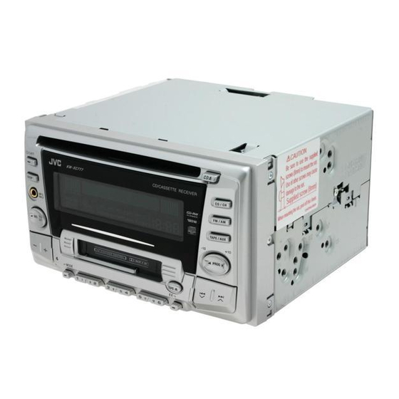
CD/CASSETTE RECEIVER
KW-XC777
Safety precaution
Preventing static electricity
Disassembly method
Adjustment method
Flow of functional operation
untill TOC read
Maintenance of laser pickup
Replacement of laser pickup
Description of major ICs
x
ao
u163
y
i
COPYRIGHT
2002 VICTOR COMPANY OF JAPAN, LTD.
http://www.xiaoyu163.com
2 9
8
Q Q
3
6 7
1 3
1 5
EX
1- 2
1- 3
1- 4
1-23
1-27
1-29
1-29
1-30~47
co
.
KW-XC777
9 4
2 8
Area Suffix
U
Other Areas
0 5
8
2 9
9 4
2 8
m
9 9
9 9
No.49687
Feb. 2002
Advertisement
Table of Contents

Related Manuals for JVC KW-XC777


Summary of Contents for JVC KW-XC777
- Page 1 KW-XC777 3 7 63 1515 0 SERVICE MANUAL CD/CASSETTE RECEIVER KW-XC777 Area Suffix Other Areas L 13942296513 Contents Safety precaution 1- 2 Preventing static electricity 1- 3 Disassembly method 1- 4 Adjustment method 1-23 Flow of functional operation untill TOC read...
- Page 2 KW-XC777 3 7 63 1515 0 Safety precaution Burrs formed during molding may be left over on some parts of the chassis. Therefore, pay attention to such burrs in the case of preforming repair of this system. Please use enough caution not to see the beam directly or touch it in case of an adjustment or operation check.
- Page 3 KW-XC777 3 7 63 1515 0 Preventing static electricity 1.Grounding to prevent damage by static electricity Electrostatic discharge (ESD), which occurs when static electricity stored in the body, fabric, etc. is discharged, can destroy the laser diode in the traverse unit (optical pickup). Take care to prevent this when performing repairs.
- Page 4 KW-XC777 3 7 63 1515 0 Disassembly method Joint a Removing the front panel assembly (See Fig.1 to 3) Remove the four screws A on both sides of the body. Release four joints a on both sides of the body using a screwdriver and remove the front panel assembly toward the front.
- Page 5 KW-XC777 3 7 63 1515 0 Removing the system control board / switch board (See Fig.4 to 5) System control board Prior to performing the following procedure, remove the front panel assembly. Remove the twelve screws B retaining the system control board.
- Page 6 KW-XC777 3 7 63 1515 0 Removing the CD player section / cassette player section (See Fig.6 to 10) Prior to performing the following procedure, remove the front panel assembly. Remove the ten screws D, the screw E and F attaching the rear panel on the back of the body.
- Page 7 KW-XC777 3 7 63 1515 0 <CD player section> Prior to performing the following procedure, remove Main board the front panel assembly, the CD player section and the cassette player section. Removing the main board (See Fig.11) CN601 Remove the three screws J attaching the main board.
- Page 8 KW-XC777 3 7 63 1515 0 <Cassette player section> Main board CN972 Prior to performing the following procedures, remove the front panel assembly, the CD player section and the cassette player section. Removing the main board (See Fig.13) Disconnect the card wire from connector CN972 on the main board.
- Page 9 KW-XC777 3 7 63 1515 0 Damper bracket <CD mechanism section> CD mechanism assembly Removing the CD mechanism control board (See Fig.1 and 2) Unsolder the part a and b on the CD mechanism control board. Remove the stator fixing the CD mechanism control board and the damper bracket (To remove the stator smoothly, pick up the center part).
- Page 10 KW-XC777 3 7 63 1515 0 Damper bracket assembly CD mechanism Removing the CD mechanism assembly (See Fig.1, 6 to 9) Prior to performing the following procedure, remove the CD mechanism control board and the front bracket (loading motor).
- Page 11 KW-XC777 3 7 63 1515 0 Removing the feed motor assembly FD screw Part i Feed motor assembly (See Fig.10) Prior to performing the following procedure, remove the CD mechanism control board, the front bracket Part j (loading motor) and the CD mechanism assembly.
- Page 12 KW-XC777 3 7 63 1515 0 REFERENCE: Prior performing following procedures, turn the mode gear on the bottom of the body until the respective part comes to the EJECT position (Refer to Fig.1). Removing the cassette guide (See Fig.2)
- Page 13 KW-XC777 3 7 63 1515 0 Cassette holder assembly Removing the cassette hanger assembly / cassette holder (See Fig.4 to 7) Check the mode is set to EJECT. Push down the Boss d Side bracket Cassette hanger front part of the cassette holder and move in the assembly direction of the arrow to release the joint c.
- Page 14 KW-XC777 3 7 63 1515 0 Removing the side bracket assembly Side bracket assembly (See Fig.8 to 10) Joint i Remove the screw A attaching the side bracket assembly. Joint j Detach the front side of the side bracket assembly upward and pull out forward to release the joint i and j in the rear.
- Page 15 KW-XC777 3 7 63 1515 0 Removing the pinch arm (F) assembly (See Fig.11 and 12) Remove the polywasher and pull out the pinch arm (F) assembly. Remove the compulsion spring. Polywasher Pinch arm Polywasher Pinch arm (F) assembly...
- Page 16 KW-XC777 3 7 63 1515 0 Removing the head / tape guide (See Fig.16 and 17) Slide chassis assembly REFERENCE: It is not necessary to remove the slide chassis assembly. Remove the band attaching the wire to the head.
- Page 17 KW-XC777 3 7 63 1515 0 Disassembling the flywheel assembly (F) (See Fig.20 and 21) Push and turn counterclockwise the spring holder (F) Flywheel assembly (F) Flywheel assembly (R) to release the three joints p on the bottom of the flywheel.
- Page 18 KW-XC777 3 7 63 1515 0 Removing the gear base arm / gear base Gear base arm Joint t link assembly (See Fig.25 to 27) Joints s Move the gear base arm in the direction of the arrow. Hook u...
- Page 19 KW-XC777 3 7 63 1515 0 Mode gear Mode switch actuator Removing the mode gear (See Fig.28 and 31) Remove the polywasher on the bottom and pull out the mode gear. Removing the mode switch actuator Polywasher (See Fig.28, 29 and 31) Pull out the mode switch actuator at the bottom.
- Page 20 KW-XC777 3 7 63 1515 0 Slot e' Removing the gear base assembly / take up gear / reflector gear (See Fig.32 to 34) Push in the pin d’ of the gear base assembly on the upper side of the body and move the reflector gear toward the bottom, then pull out.
- Page 21 KW-XC777 3 7 63 1515 0 Removing the side bracket assembly (See Fig.35 to 39) Remove the eject cam plate spring. Push the joint f‘ through the slot to remove the load rack downward. Joint f' Move the eject cam limiter in the direction of the arrow to release it from the boss g’...
- Page 22 KW-XC777 3 7 63 1515 0 Main motor Removing the main motor assembly / assembly sub motor assembly (See Fig.40 to 42) Reduction gear (B) Belt Reduction Remove the belt at the bottom. gear (A) Remove the polywasher and pull out the mode gear.
- Page 23 KW-XC777 3 7 63 1515 0 Adjustment method Tuner area Test Instruments reqired for adjustment Band range 1.Digital osclloscope(100MHz) FM : 87.5MHz to 108MHz 2.Frequency Counter meter AM : 531kHz to 1602kHz 3.Electric voltmeter 4.Wow & flutter meter 5.Test Tapes...
- Page 24 KW-XC777 3 7 63 1515 0 Arrangment of adjusting VR402:Rch VR401:Rch (Dolby NR level adj) (Dolby NR Frequency response adj) Head amplifier board section (Reverse side) C419 C418 R412 C413 C416 C414 R416 C421 C422 R414 C412 VR401 Q401...
- Page 25 KW-XC777 3 7 63 1515 0 Item Adjustment and check method Adjust Spec 1.Tape position Playback at FWD side, use the mirror tape and Azimuth adjuste azimuth screw A and B, check the tape screw A position at tape guide position of the head.
- Page 26 KW-XC777 3 7 63 1515 0 <Service mode> 1.Service mode setting operation Power off condition, then press button, button and button together more than 2sec. 2.Service mode menu Service mode menu can select the next item by press button.
- Page 27 KW-XC777 3 7 63 1515 0 Flow of functional operation until TOC read Power ON • When the laser diode correctly Set Function to CD • When the pickup correctly moves emits to the inner area of the disc...
- Page 28 KW-XC777 3 7 63 1515 0 Feed Section Check CD 9V Is the voltage output at Is the wiring for IC621 Is 5V present at IC661 and 5V. IC621 pin "40" 5V or 0V? (56) ~ (64) correct? pin "32"? Check the vicinity of IC621.
- Page 29 KW-XC777 3 7 63 1515 0 Maintenance of laser pickup (1) Cleaning the pick up lens Before you replace the pick up, please try to clean the lens with a alcohol soaked cotton swab. (2) Life of the laser diode When the life of the laser diode has expired, the following symptoms will appear.
- Page 30 KW-XC777 3 7 63 1515 0 Description of major ICs TA2147F-X (IC601) : RF amp. 1.Terminal layout 2.Block diagram PEAK GVSW 12 RFDC 20 A L 13942296513 TEBC 50 A RFRP BOTTOM RFRPIN PEAK RFGO 1.75k 240k 15pF x0.5...
- Page 31 KW-XC777 3 7 63 1515 0 3.Pin function Pin No. Symbol Function 3.3V Power supply pin Main-beam amp input pin Main-beam amp input pin Sub-beam amp input pin Sub-beam input pin Monitor photo diode amp input pin Laser diode amp output pin APC circuit ON/OFF control signal,laser diode (LDO) control signal input or bottom/peak detection frequency change pin.
-
Page 32: Table Of Contents
KW-XC777 3 7 63 1515 0 LA4743K (IC901) : Power amp. 1.Block diagram 2200 F 0.022 F Vcc 1/2 Vcc 3/4 IN 1 OUT 1+ 0.22 F OUT 1- PWR GND1 Protective circuit OUT 2+ IN 2 OUT 2- 0.22 F... - Page 33 KW-XC777 3 7 63 1515 0 2.Terminal layout 3.Pin function Pin No. Symbol Function Header of IC Power GND RFO- Outpur(-) for front Rch STBY Stand by input Output (+) for front Rch RFO+ VCC1/2 Power input RRO- Output (-) for rear Rch...
- Page 34 KW-XC777 UPD784216AGC160 (IC701) : CPU 3 7 63 1515 0 1.Pin layout 100 ~ 81 31 ~ 50 2.Pin function (1/2) Pin No. Symbol Function Non connect Non connect Non connect Non connect Non connect Non connect Non connect...
- Page 35 KW-XC777 3 7 63 1515 0 2.Pin function (2/2) Pin No. Symbol Function 46~50 Non connect SD/SI Station detector, Stereo signal input terminal (SD : H) PLL CE Chip enable output terminal for PLL PLL DATA Data output terminal for PLL...
- Page 36 KW-XC777 3 7 63 1515 0 TC9490FA (IC621) : DSP & DAC 1.Pin layout & Block daiagram TEZI Clock generator SBAD 1-bit Servo control RFRP RFZI ZDET RFCT Digital equalizer Address automatic circuit adjustment circuit BUS0 Data CLV servo...
- Page 37 KW-XC777 3 7 63 1515 0 2.Pin function (1/2) TC9490FA(2/3) Pin No. Symbol Function Bit clock outputpin 32fs, 48fs, or 64fs selectable by command. LRCK L/R channel clock output pin."L" for L channe and "H" for R channel. Output polarity can be inverted by command.
- Page 38 KW-XC777 3 7 63 1515 0 2.Pin function (2/2) TC9490FA(3/3) Pin No. Symbol Function RFGC RF amplitude adjustment control signal output pin. TEBC Tracking balance control signal output pin. APC circuit ON/OFF signal output pin. At laser on,high impedance with UHS="L"...
- Page 39 KW-XC777 3 7 63 1515 0 UPD789166GB-590 (IC431) : CPU 1.Pin layout 44 ~ 34 12 ~ 22 2.Pin function Pin No. Symbol Function KEY0 KEY0 input terminal KEY1 KEY1 input terminal KEY2 KEY2 input terminal KEY SEL KEY in select setting terminal (H:active)
- Page 40 KW-XC777 3 7 63 1515 0 CXA2560Q (IC401) : Dolby B type noise reduction system with play back equalizer amp. 1.Pin layout & block diagram 7k/12k PBFB2 MSMODE 100k OFF/B PBRIN2 DRSW 300k MS MODE BIAS PBGND TAPESW MUTE...
-
Page 41: Stand By
KW-XC777 3 7 63 1515 0 FAN8037 (IC661) : CD driver 1. Pin layout & Block diagram 48 47 46 45 44 43 42 41 40 39 38 37 STAND BY T.S.D ALL MUTE POWER SAVE 13 14 15 16 17 18 19 20 21 22 23 24 2. - Page 42 KW-XC777 3 7 63 1515 0 HA13164A (IC911) : Regulator 1.Terminal layout 1 2 3 4 5 6 7 8 9 10 11 12 13 14 15 2.Block diagram 100u 0.1u BATT.DET OUT ANT OUT Surge Protector 0.1u EXT OUT...
-
Page 43: Vcc
KW-XC777 3 7 63 1515 0 HD74HC126FP-X (IC461,IC761) : Buffer 1.Pin layout 2.Pin function Input Output Note) H:High level L:Low level X:Irrelevant Z:Off(High-impedance) State a 3-state input 3.Block diagram Output Input Output L 13942296513 Sample as Load Circuit 1... -
Page 44: Out
KW-XC777 3 7 63 1515 0 IC-PST9333U-X (IC432,IC791) : Regulator 1. Pin layout 2. Block diagram VOUT VOUT 3. Pin function Pin No. Symbol Function Non connect GND terminal VOUT Reset signal output terminal Vcc terminal/Voltage detect terminal L 13942296513 NJM4580V-X (IC961) : Ope amp. - Page 45 KW-XC777 3 7 63 1515 0 LC75878W (IC501) : LCD driver 1. Pin layout 100 ~ 76 26 ~ 50 2. Block diagram GENERAL COMMON SEGMENT DRIVER & LATCH PORT DRIVER CONTROL CLOCK REGISTER GENERATOR VLCD CONTRAST SHIFT REGISTER...
- Page 46 KW-XC777 3 7 63 1515 0 M61508FP-X (IC951) : E. volume 1. Pin layout & Block diagram LOUDNESS (Digital) (Anarog) 3BAND TONE CONTROL (BASS/MID/TREBLE) Soft select Z E R O C RO S S D E T E C T O R...
- Page 47 KW-XC777 3 7 63 1515 0 TB2118F-X (IC21) : PLL 1.Terminal Layout 2.Block diagram Constant power supply voltage Buff. ON/OFF AM CP. Phase OSC circuit Reference Counter Comparator switch FM VCO 4-bit Prescaler Swallow counter 12-bit AMVCO Programmable counter REG.
- Page 48 KW-XC777 3 7 63 1515 0 L 13942296513 u163 VICTOR COMPANY OF JAPAN, LIMITED MOBILE ELECTRONICS DIVISION PERSONAL & MOBILE NETWORK BUSINESS UNIT. 10-1,1Chome,Ohwatari-machi,Maebashi-city,371-8543,Japan 200202 (No.49687) http://www.xiaoyu163.com...
- Page 49 KW-XC777 3 7 6 3 1 5 1 5 0 Block diagram TU-L TU-R FM/AM VA,VB,VC,VD,VE,VF,LD TUNER SEEK IC951 IC901 MONO E.VOL PICKUP POWER IC TRACKING+ SD/ST IC661 FM/AM IC601 TRACKING+ S.METER CD-L CD-RW FOCUS+ RF AMP CD-R FRONTL+...
- Page 50 KW-XC777 KW-XC777 3 7 6 3 1 5 1 5 0 Standard schematic diagrams Main amp section QAU0223-001 R291 CH-Rch 4.7k C291 1/50 C201 IC951 R203 R201 R271 TAPE-Rch C272 1/50 R221 M61508FP-X 1/50 IC901 R241 CD-Rch C242 LA4743K...
- Page 51 KW-XC777 3 7 6 3 1 5 1 5 0 CD servo control, LCD & Key control section CD-Rch R252 C253 R251 C252 4.7/25 R253 R-CH 120p C663 C612 R613 220/10 D691 Q691 C662 R694 2SD601A/RS/-X 0.01 IC661 R614...
- Page 52 KW-XC777 KW-XC777 3 7 6 3 1 5 1 5 0 Mecha control section IC402 LB1641 CN403 QGF1219F1-10 C425 0.01 Q403 2SB1322/RS/-T C424 R424 R425 2.2k R426 Q402 R401 DTC114EKA-X R448 100k IC432 R417 IC-PST9333U-X R420 Q401 R443 X431 C411 2.2K...
- Page 53 KW-XC777 3 7 6 3 1 5 1 5 0 Printed circuit boards Main board (Forward side) Main board (Reverse side) IC911 L911 IC911 CN911 Q914 R161 R261 R162 R262 CN951 CN951 R926 R922 CN702 CN702 C927 B231 C783...
- Page 54 KW-XC777 KW-XC777 3 7 6 3 1 5 1 5 0 Switch board (Forward side) Switch board (Reverse side) D522 R590 R589 R592 R588 R593 R591 R587 S533 R599 R554 D561 D562 R598 D521 D529 S511 D530 R540 S501...
- Page 55 KW-XC777 3 7 63 1515 0 PARTS LIST [ KW-XC777 ] * All printed circuit boards and its assemblies are not available as service parts. Area suffix U --------------------- Other Areas L 13942296513 - Contents - 3- 2 Exploded view of general assembly and parts list (Block No.M1) 3- 5 CD mechanism assembly and parts list (Block No.MB)
- Page 56 KW-XC777 3 7 63 1515 0 Exploded view of general assembly and parts list Block No. L 13942296513 u163 http://www.xiaoyu163.com...
- Page 57 KW-XC777 3 7 63 1515 0 Parts list (General assembly) Block No. M1MM Item Description Parts number Parts name Q'ty Area --------------- CD MECHA 1 TN-CCD1001Z-138S QYSDST2004Z SCREW LV40847-002A SPACER --------------- CASSETTE MECHA 1 CDS-802JE3 LV21157-001A MECHA BKT(CA) SCREW...
- Page 58 KW-XC777 3 7 63 1515 0 Parts list (General assembly) Block No. M1MM Item Description Parts number Parts name Q'ty Area QUQ210-2107CJ FFC WIRE QUQ210-1512CJ FFC WIRE VMA4652-001SS EARTH PLATE LV42302-001A POWER IC BRACKE LV42670-001A REG.IC BRACKET QMFZ047-150-T FUSE...
- Page 59 KW-XC777 3 7 63 1515 0 CD mechanism assembly and parts list Block No. Grease G-31SA TN-CCD1001Z-138S G-31SA(Bottom side) RX-405 L 13942296513 u163 106 29 http://www.xiaoyu163.com...
- Page 60 KW-XC777 3 7 63 1515 0 Parts list (CD mechanism) Block No. MBMM Item Description Parts number Parts name Q'ty Area 30310101T FRAME 30310103T DANPER PIN 30310107T UPPER PLATE 30310108T SEL STOP PLATE 30310142T SEL ARM (L)L SEL ARM (R)L...
- Page 61 KW-XC777 3 7 63 1515 0 Parts list (CD mechanism) Block No. MBMM Item Description Parts number Parts name Q'ty Area 68150242T CONNECTOR 1 TKC-W26X-A1 30311105T SOPPORT PLATE 30311138T GR MT BLK(N) 30311109T LDG GEAR (2) 30311110T LDG GEAR (3)
- Page 62 KW-XC777 3 7 63 1515 0 Cassette mechanism assembly and parts list Block No. CDS-802JE3 L 13942296513 u163 http://www.xiaoyu163.com...
- Page 63 KW-XC777 3 7 63 1515 0 Parts list (Cassette mechanism) Block No. MPMM Item Description Parts number Parts name Q'ty Area X-0802-1009S MAIN CHASSIS AS X-0802-1002S SLIDE CHASSIS A X-0802-1003S SIDE BKT ASSY X-0802-1004S CASSETTE HANGER X-0802-1005S PINCH ARM(F)ASS...
- Page 64 KW-XC777 3 7 63 1515 0 Parts list (Cassette mechanism) Block No. MPMM Item Description Parts number Parts name Q'ty Area 1-0802-4008S REEL DRIVER SPG 1-0802-4013S COMPULSION SPG 1-0802-5001S BELT 1-0802-5002S FELT 1 7.5*18.5*1 1-0802-5003S AZIMUTH SCREW FELT 1-0802-5004S 1 11*18.5*1...
- Page 65 KW-XC777 3 7 63 1515 0 Grease point 1/2 FG-84M MEA-512R MEN-223 SW-902 CFD-409 CFD-250H EP-56 SW-474B L 13942296513 u163 3-11 http://www.xiaoyu163.com...
- Page 66 KW-XC777 3 7 63 1515 0 Grease point 2/2 L 13942296513 u163 3-12 http://www.xiaoyu163.com...
- Page 67 KW-XC777 3 7 63 1515 0 Electrical parts list (Main board) Block No. 01 Item Parts number Parts name Remarks Area Item Parts number Parts name Remarks Area NCB31HK-103X C CAPACITOR C 242 QERF1HM-105Z E CAPACITOR 1.0MF 20% 50V...
- Page 68 KW-XC777 3 7 63 1515 0 Electrical parts list (Main board) Block No. 01 Item Parts number Parts name Remarks Area Item Parts number Parts name Remarks Area C 703 NCS31HJ-8R0X C CAPACITOR CN701 QGB1004K1-20 CONNECTOR C 704 NDC31HJ-270X...
- Page 69 KW-XC777 3 7 63 1515 0 Electrical parts list (Main board) Block No. 01 Item Parts number Parts name Remarks Area Item Parts number Parts name Remarks Area Q 201 2SD1048/6-7/-X TRANSISTOR R 153 NRSA63J-123X MG RESISTOR Q 202...
- Page 70 KW-XC777 3 7 63 1515 0 Electrical parts list (Main board) Block No. 01 Item Parts number Parts name Remarks Area Item Parts number Parts name Remarks Area R 746 NRSA63J-102X MG RESISTOR R 630 NRSA63J-0R0X MG RESISTOR R 747...
- Page 71 KW-XC777 3 7 63 1515 0 Electrical parts list (Front board) Block No. 02 Item Parts number Parts name Remarks Area Item Parts number Parts name Remarks Area C 501 NBE21AM-106X E CAPACITOR R 518 NRSA63J-222X MG RESISTOR C 502...
- Page 72 KW-XC777 3 7 63 1515 0 Electrical parts list (Front board) Block No. 02 Item Parts number Parts name Remarks Area S 501 NSW0066-001X TACT SWITCH S 502 NSW0066-001X TACT SWITCH S 503 NSW0066-001X TACT SWITCH S 504 NSW0066-001X...
- Page 73 KW-XC777 3 7 63 1515 0 Electrical parts list (Mecha control board) Block No. 03 Item Parts number Parts name Remarks Area Item Parts number Parts name Remarks Area C 401 NCS31HJ-101X C CAPACITOR R 420 NRSA63J-124X MG RESISTOR...
- Page 74 KW-XC777 3 7 63 1515 0 Packing materials and accessories parts list Block No. Block No. A1~A3 A11, A12 L 13942296513 u163 3-20 http://www.xiaoyu163.com...
- Page 75 KW-XC777 3 7 63 1515 0 Parts list (Packing) Block No. M3MM Item Description Parts number Parts name Q'ty Area QPC03004315P POLY BAG 1 SET QPA01703505P POLY BAG 1 INST.BOOK QPA00801205 POLY BAG 1 SCREW ASS'Y LV33538-001A CARTON LV10614-001A...