
Related Manuals for National Instruments NI 9411


Summary of Contents for National Instruments NI 9411
- Page 1 GETTING STARTED GUIDE NI 9411 6 DI, ±5 V to 24 V, Differential/Single-Ended, 500 ns...
-
Page 2: Safety Guidelines
This document explains how to connect to the NI 9411. Before you begin, complete the software and Note hardware installation procedures in your chassis documentation. The guidelines in this document are specific to Note the NI 9411. The other components in the system might not meet the same safety ratings. -
Page 3: Safety Voltages
Such voltage measurements include signal levels, special equipment, limited-energy parts of equipment, circuits powered by regulated low-voltage sources, and electronics. NI 9411 Getting Started Guide | © National Instruments | 3... -
Page 4: Safety Guidelines For Hazardous Locations
CAT III, or CAT IV. Safety Guidelines for Hazardous Locations The NI 9411 is suitable for use in Class I, Division 2, Groups A, B, C, D, T4 hazardous locations; Class I, Zone 2, AEx nA IIC T4 and Ex nA IIC T4 hazardous locations; and nonhazardous locations only. -
Page 5: Special Conditions For Hazardous Locations Use In Europe And Internationally
II 3G and is suitable for use in Zone 2 hazardous locations, in ambient temperatures of -40 °C ≤ Ta ≤ 70 °C. If you are using the NI 9411 NI 9411 Getting Started Guide | © National Instruments | 5... -
Page 6: Electromagnetic Compatibility Guidelines
This product was tested and complies with the regulatory requirements and limits for electromagnetic compatibility (EMC) stated in the product specifications. These requirements and limits provide reasonable protection against harmful interference 6 | ni.com | NI 9411 Getting Started Guide... -
Page 7: Special Conditions For Marine Applications
(shipboard) applications. To verify Lloyd’s Register certification for a product, visit ni.com/certification and search for the LR certificate, or look for the Lloyd’s Register mark on the product. NI 9411 Getting Started Guide | © National Instruments | 7... -
Page 8: Preparing The Environment
EMC performance is attained. Preparing the Environment Ensure that the environment in which you are using the NI 9411 meets the following specifications. Operating temperature -40 °C to 70 °C... -
Page 9: Connecting The Ni 9411
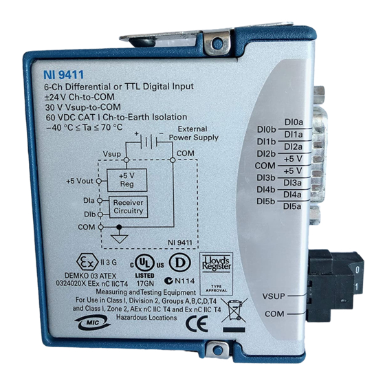
Connecting the NI 9411 The NI 9411 provides connections for 6 digital input channels. NI 9411 Getting Started Guide | © National Instruments | 9... - Page 10 Figure 1. NI 9411 Pinout DI0a DI0b DI1a DI1b DI2a DI2b Supply (+5 V Supply (+5 V DI3b DI3a DI4b DI4a DI5b DI5a 10 | ni.com | NI 9411 Getting Started Guide...
- Page 11 Supply (+5 Vout) 5 V power output connection for external devices Table 2. Screw-Terminal Connector Signal Descriptions Signal Description Common reference connection to isolated ground Vsup Voltage supply connection NI 9411 Getting Started Guide | © National Instruments | 11...
- Page 12 Connecting an External Power Supply to the NI 9411 You can connect an external power supply to the NI 9411. The external power supply provides power for external devices through the NI 9411 +5 Vout terminal. Connecting an external power supply to the NI 9411 is optional, depending on your application.
-
Page 13: Connecting A Differential Device To The Ni 9411
– Differential Device NI 9411 The NI 9411 compares the difference between DIa and DIb to the digital logic levels to determine if the signal is in the high range or low range. Refer to the device datasheet at ni.com/manuals for the digital logic levels. - Page 14 Single-Ended Device NI 9411 The NI 9411 compares the difference between DIa and COM to the digital logic levels to determine if the signal is in the high range or low range. 14 | ni.com | NI 9411 Getting Started Guide...
-
Page 15: Connecting An Encoder To The Ni 9411
A signals to measure rotational speed. Use the phase B signals to measure direction. Use the index signals to measure the number of rotations. You can connect differential and single- ended encoders to the NI 9411. NI 9411 Getting Started Guide | © National Instruments | 15... - Page 16 Figure 5. Connecting a Differential Encoder to the NI 9411 External Power Supply – +5 V +5 V +5 V DI0a Receiver DI0b A– Circuitry DI1a Receiver DI1b B– Circuitry DI2a Index+ Receiver DI2b Index– Circuitry Differential Encoder NI 9411...
- Page 17 +5 V DI0a Receiver DI0b Circuitry DI1a Receiver DI1b Circuitry DI2a Receiver Index DI2b Circuitry Single-Ended Encoder NI 9411 I/O Protection The NI 9411 provides I/O protection for each channel. NI 9411 Getting Started Guide | © National Instruments | 17...
-
Page 18: High-Vibration Application Connections
If your application is subject to high vibration, NI recommends that you follow these guidelines to protect connections to the NI 9411: • Use ferrules to terminate wires to the detachable connector. • Use the NI 9948 backshell kit. 18 | ni.com | NI 9411 Getting Started Guide... -
Page 19: Where To Go Next
NI 9411 Datasheet NI-RIO Help NI-DAQmx Help LabVIEW FPGA Help LabVIEW Help RELATED INFORMATION C Series Documentation Services & Resources ni.com/services ni.com/info cseriesdoc Located at ni.com/manuals Installs with the software NI 9411 Getting Started Guide | © National Instruments | 19... -
Page 20: Worldwide Support And Services
(EMC) and product safety. You can obtain the DoC for your product by visiting ni.com/certification. If your product supports calibration, you can obtain the calibration certificate for your product at ni.com/calibration. 20 | ni.com | NI 9411 Getting Started Guide... - Page 21 United States, visit the Worldwide Offices section of ni.com/niglobal to access the branch office websites, which provide up-to-date contact information, support phone numbers, email addresses, and current events. NI 9411 Getting Started Guide | © National Instruments | 21...
- Page 22 U.S. Government Customers: The data contained in this manual was developed at private expense and is subject to the applicable limited rights and restricted data rights as set forth in FAR 52.227-14, DFAR 252.227-7014, and DFAR 252.227-7015. © 2003—2015 National Instruments. All rights reserved. 373506F-01 Dec15...