Table of Contents
Advertisement
Quick Links
SPLIT-TYPE, HEAT PUMP AIR CONDITIONERS
SPLIT-TYPE, AIR CONDITIONERS
TECHNICAL & SERVICE MANUAL
Series PCA
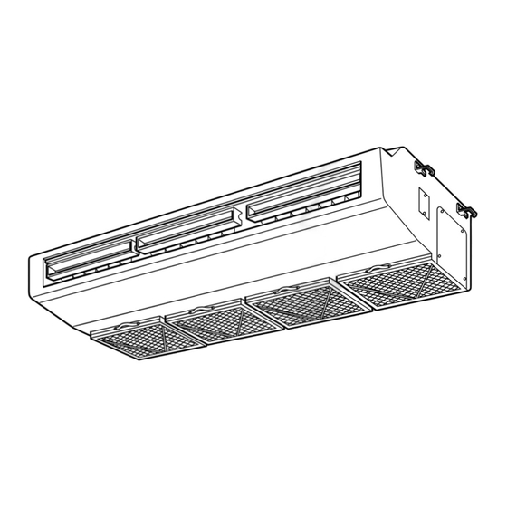
Indoor unit
[Model names]
PCA-P3HA
PCA-P5HA
INDOOR UNIT
CENTRALLY CONTROLLED
CLOCK
CHECK
˚C
STAND BY
ERROR CODE
DEFROST
TEMP.
REMOTE CONTROLLER
Ceiling Suspended
[Service Ref.]
PCA-P3HA
PCA-P5HA
1Hr.
ON OFF
˚C
FILTER
CHECK MODE
TEST RUN
NOT AVAILABLE
FUNCTION
ON/OFF
R407C
• Refer to the OCT03
REVISED EDITION-E as
regarding control relation.
• This manual does not cover
outdoor units.When serving
them, please refer to the
service manual No.OC261
REVISED EDITION-B and
this manual in a set.
CONTENTS
1. SAFETY PRECAUTION ···································2
2. PART NAMES AND FUNCTIONS····················4
3. SPECIFICATIONS ············································6
4. DATA·······························································10
5. OUTLINES AND DIMENSIONS ·····················21
6. WIRING DIAGRAM············································23
7. REFRIGERANT SYSTEM DIAGRAM ··················24
8. TROUBLESHOOTING ···································25
9. DISASSEMBLY PROCEDURE ······················26
10. PARTS LIST ···················································30
11. OPTIONAL PARTS·········································33
2003
No. OC289
Advertisement
Table of Contents

Related Manuals for Mitsubishi Electric PCA-P3HA


Summary of Contents for Mitsubishi Electric PCA-P3HA
-
Page 1: Table Of Contents
R407C Ceiling Suspended Series PCA Indoor unit • Refer to the OCT03 [Model names] [Service Ref.] REVISED EDITION-E as PCA-P3HA regarding control relation. PCA-P3HA • This manual does not cover PCA-P5HA outdoor units.When serving PCA-P5HA them, please refer to the service manual No.OC261... -
Page 2: Safety Precaution
SAFETY PRECAUTION Cautions for using with the outdoor unit which adopts R407C refrigerant. · Do not use the existing refrigerant piping. -The old refrigerant and refrigerant oil in the existing piping contains a large amount of chlorine which may cause the refriger- ant oil of the new unit to deteriorate. - Page 3 [1] Service tools Use the below service tools as exclusive tools for R407C refrigerant. Tool name Specifications Gauge manifold ·Only for R407C. ·Use the existing fitting SPECIFICATIONS. (UNF7/16) ·Use high-tension side pressure of 3.43MPa or over. Charge hose ·Only for R407C. ·Use pressure performance of 5.10MPa or over.
-
Page 4: Part Names And Functions
PART NAMES AND FUNCTIONS Indoor (Main) Unit Left/right guide vanes Change the direction of airflow Air outlet from the horizontal blower. Oil filter (Air intake) w It prevents oil from Up/down guide vanes getting into the unit. Change the direction of airflow from the vartical blower. -
Page 5: Operation Lamp
Display In this display example on the bot- CENTRALLY CLOCK display tom left, a condition where all dis- CONTROLLED display play lamps light is shown for expla- The current time , start time and stop time can be displayed in ten second nation purposes although this differs This indicates when the unit is con- intervals by pressing the time switch... -
Page 6: Specifications
SPECIFICATIONS 1. Heat pump type Rating Conditions (ISO T1) Service Ref. PCA-P3HA Item Function Cooling Heating Btu/h 25,600 31,400 Capacity 7,500 9,200 Total input 3.36 3.41 Service Ref. PCA-P3HA Power supply Single phase, 50Hz, 220-230-240V Input 0.09 0.09 Running current 0.43... - Page 7 Rating Conditions (ISO T1) Service Ref. PCA-P5HA Item Function Cooling Heating 44,400 Btu/h 54,600 Capacity 13,000 16,000 Total input 4.90 4,98 Service Ref. PCA-P5HA Power supply Single phase, 50Hz, 220-230-240V Input 0.26 0.26 Running current 1.19 1.19 Starting current 2.38 2.38 External finish Stainless steel...
- Page 8 Rating Conditions (ISO T1) Service Ref. PCA-P3HA Item Function Cooling Btu/h 25,600 Capacity 7,500 Total input 3.36 Service Ref. PCA-P3HA Power supply Single phase, 50Hz, 220-230-240V Input 0.09 Running current 0.41 Starting current 0.86 External finish Stainless steel Heat exchanger Plate fin coil Fan(drive))No.
- Page 9 Rating Conditions (ISO T1) Service Ref. PCA-P5HA Item Function Cooling Btu/h 44,400 Capacity 13,000 Total input 4.90 Service Ref. PCA-P5HA Power supply Single phase, 50Hz, 220-230-240V Input 0.26 Running current 1.19 Starting current 2.38 External finish Stainless steel Heat exchanger Plate fin coil Fan(drive))No.
-
Page 10: Data
DATA 1. PERFORMANCE DATA (240V) 1) COOLING CAPACITY<1> PCA-P3HA Outdoor intake air D.B.(°C) Indoor Indoor Intake air Intake air D.B.(°C) W.B.(°C) SHC(W) P.C. SHC(W) P.C. SHC(W) P.C. 7,425 4,604 0.62 2.69 7,200 4,464 0.62 2.84 6,975 4,325 0.62 3.01 7,950 3,975 0.50... - Page 11 COOLING CAPACITY<2> PCA-P3HA Outdoor intake air D.B.(°C) Indoor Indoor Intake air Intake air D.B.(°C) W.B.(°C) SHC(W) P.C. SHC(W) P.C. SHC(W) P.C. 6,675 4,139 0.62 3.23 6,375 3,953 0.62 3.46 6,075 3,767 0.62 3.75 7,200 3,600 0.50 3.31 6,975 3,488 0.50 3.56...
- Page 12 COOLING CAPACITY<3> PCA-P5HA Outdoor intake air D.B.(°C) Indoor Indoor Intake air Intake air D.B.(°C) W.B.(°C) SHC(W) P.C. SHC(W) P.C. SHC(W) P.C. 12,870 8,366 0.65 3.92 12,480 8,112 0.65 4.14 12,090 7,859 0.65 4.39 13,780 7,303 0.53 3.99 13,390 7,097 0.53 4.21 12,935 6,856...
- Page 13 COOLING CAPACITY<4> PCA-P5HA Outdoor intake air D.B.(°C) Indoor Indoor Intake air Intake air D.B.(°C) W.B.(°C) SHC(W) P.C. SHC(W) P.C. SHC(W) P.C. 11,570 7,521 0.65 4.70 11,050 7,183 0.65 5.05 10,530 6,845 0.65 5.46 12,480 6,614 0.53 4.83 12,090 6,408 0.53 5.19 11,310 5,994...
- Page 14 Cooling capacity correction factors Refrigerant piping length (one way) Service Ref. PCA-P3HA 1.00 0.981 0.968 0.952 0.940 0.925 0.913 0.900 0.886 0.874 PCA-P5HA 1.00 0.981 0.968 0.952 0.940 0.925 0.913 0.900 0.886 0.874 Cooling INDOOR W.B.(°C) INDOOR W.B.(°C) OUTDOOR D.B.(°C)
- Page 15 Service Ref. P.C. P.C. P.C. P.C. P.C. P.C. D.B.(°C) 5,842 2.01 6,348 2.22 7,084 2.56 9,292 3.07 10,488 3.41 11,684 3.68 PCA-P3HA 5,612 2.18 6,072 2.39 6,716 2.76 8,970 3.31 10,120 3.68 11,270 3.96 5,428 2.32 5,888 2.59 6,440 3.00 8,464 3.51...
-
Page 16: Electrical Data
2. ELECTRICAL DATA 2.1. Heat pump type Rating Conditions (ISO T1) Indoor·······220V 50Hz Single phase Outdoor····220V 50Hz Singel phase / 380V 50Hz 3 phase Service Indoor unit PCA-P3HA PCA-P5HA Ref. Outdoor unit PUH-P3VGAA PUH-P3YGAA PUH-P5YGAA Mode Cooling Heating Cooling Heating... - Page 17 2.2. Cooling only type Rating Conditions (ISO T1) Indoor·······220V 50Hz Single phase Outdoor····220V 50Hz Singel phase / 380V 50Hz 3 phase Service Indoor unit PCA-P3HA PCA-P5HA Ref. Outdoor unit PU-P3VGAA PU-P3YGAA PU-P5YGAA Mode Cooling Cooling Cooling Capacity (W) 7,500 7,500...
-
Page 18: Standard Operation Data
3. STANDARD OPERATION DATA 3.1 Heat pump type Rating Conditions (ISO T1) Service Ref. PCA-P3HA PCA-P5HA Mode Cooling Heating Cooling Heating Capacity 7,500 9,200 13,000 16,000 3.41 4.98 Input 3.36 4.90 Indoor unit Service Ref. PCA-P3HA PCA-P5HA Phase, Hz 1, 50... - Page 19 3.2 Cooling only type Rating Conditions (ISO T1) Service Ref. PCA-P3HA PCA-P5HA Mode Cooling Cooling Capacity 7,500 13,000 3.36 4.90 Input Indoor unit Service Ref. PCA-P3HA PCA-P5HA 1, 50 1, 50 Phase, Hz Volts Amperes 0.43 1.19 PU-P3VGAA PU-P5YGAA Outdoor unit Service Ref.
-
Page 20: Noise Criterion Curves
5. NOISE CRITERION CURVES PCA-P3HA PCA-P5HA NOTCH SPL(dB) LINE NOTCH SPL(dB) LINE NC-70 NC-70 NC-60 NC-60 NC-50 NC-50 NC-40 NC-40 NC-30 NC-30 APPROXIMATE APPROXIMATE TERESHOLD OF TERESHOLD OF HEARING FOR HEARING FOR NC-20 NC-20 CONTINUOUS CONTINUOUS NOISE NOISE 1000 2000... -
Page 21: Outlines And Dimensions
OUTLINES AND DIMENSIONS PCA-P3HA Unit : mm... - Page 22 PCA-P5HA Unit : mm...
-
Page 23: Wiring Diagram
WIRING DIAGRAM PCA-P3HA PCA-P5HA INDOOR UNIT OUTDOOR UNIT <PU(H)-P3VGAA .UK> PCA-P5HA POWER SUPPLY CN2S(WHT) ~(1PHASE) 220-230-240V 50Hz DC14V 2 3 4 CONT.BOARD OUTDOOR CN01(BLU) CN02(WHT) <PU(H)-P3/5YGAA .UK> POWER SUPPLY 3N~(3PHASE 4WIRES) POWER 380-400-415V 50Hz D.HEATER CN03 (WHT) CNC (RED) POWER... -
Page 24: Refrigerant System Diagram
REFRIGERANT SYSTEM DIAGRAM Unit : mm PCA-P3HA / PUH-3VGAA .UK, PUH-3YGAA <4-way valve solenoid coil> Heating : ON High pressure Ball valve Cooling : OFF Outdoor unit Refrigerant pipe 4-way valve protect switch Indoor unit Outdoor heat exchanger 15.88A({5/8") (#50) -
Page 25: Troubleshooting
TROUBLESHOOTING HOW TO CHECK THE PARTS PCA-P3HA PCA-P5HA Parts name Check points Room temperature Disconnect the connector then measure the resistance using a tester. thermistor (TH1) (Surrounding temperature 10:~30:) Pipe temperature thermistor (TH2) Normal Abnormal (Refer to the next pege for a detail.) Condenser/Evaporator 4.3k"~9.6k"... -
Page 26: Disassembly Procedure
DISASSEMBLY PROCEDURE PCA-P5HA OPERATING PROCEDURE PHOTOS&ILLUSTRATIONS 1. Removing the oil filter Figure 1 (1) Slide the oil filter towards you to remove. (See figure 1.) Oil filter 2. Removing the terminal block box cover Photo 1 Filter rail Fan guard (1) Remove the oil filter. - Page 27 OPERATING PROCEDURE PHOTOS&ILLUSTRATIONS 4. Removing the fan motor Photo 4 (1) Remove the oil filter. (See figure 1.) (2) Remove the control box cover. (See photo 2.) Filter reil (3) Remove the room temperature thermistor connector (CN20) on the indoor controller board. (See photo 3.) (4) Remove a filter rail that is the nearest to the control box.
- Page 28 OPERATING PROCEDURE PHOTOS 6. Removing the pipe temperature thermistor Photo 8 Relay connector (1) Remove the oil filter. (See figure 1.) (2) Remove the fan guard. (See photo 1.) (3) Remove the terminal block box cover. (4) Remove the white relay connector (2P) in the terminal block box.
- Page 29 OPERATING PROCEDURE PHOTOS 9. Removing the guide vane Photo 13 Guide vane (1) Remove the oil filter. (See figure 1.) (2) Remove the 3 filter rails. (See photo 1, 4.) (3) Remove the under panel. (See photo 11.) (4) Remove the drain pan. (See photo 12.) (5) Remove the 3 screws (4 10) for guide vane, and remove the guide vane.
-
Page 30: Parts List
PARTS LIST STRUCTURAL PART PCA-P3HA PCA-P5HA Q'ty / set Price Wiring Recom- Remarks Parts No. Parts Name Specifications PCA- Diagram mended (Drawing No.) Symbol Q'ty Unit Amount P3HA P5HA R01 13N 809 LEG-L R01 13N 662 SIDE PLATE-L T7W E02 676... - Page 31 18,19 FAN AND HEATER PARTS PCA-P3HA PCA-P5HA Part numbers that are circled are not shown in the figure. Q'ty / set Price Wiring Recom- Remarks Parts No. Parts Name Specifications PCA- Diagram mended (Drawing No.) Symbol Q'ty Unit Amount P3HA...
- Page 32 ELECTRICAL PARTS PCA-P3HA PCA-P5HA 7, 8 CENTRALLY CONTROLLED 1Hr. ON OFF ˚C CLOCK CHECK FILTER CHECK MODE ˚C TEST RUN STAND BY ERROR CODE FUNCTION DEFROST NOT AVAILABLE TEMP. ON/OFF CN02 CN2S CN29 CN20 CN21 CN2D CN22 TO OUTDOOR TO REMOTE...
-
Page 33: Optional Parts
OPTIONAL PARTS 1. TIMER Part No. PAC-SC32PTA (with set back function) Model Name Program timer 1-1. Program timer specifications Part name Program timer Parts No. PAC-SC32PTA Exterior dimensions (inch) 5-4/32 4-23/32 23/32 (130 120 18mm) Installation Wall mount Type of clock Quartz Clock accuracy 50 second / month at 25:... - Page 34 1-3. How to connect program timer (1) Install the program timer next to the remote controller the same way as the remote controller is installed. (2) Connect the program timer and the remote controller with a 5-wire cable as shown in the figure below Connect to indoor unit NOTE:While the program timer is connected to the remote controller, the with 2-wire cable.
- Page 35 2. Duct flange for frech air Part No. PAC-SF28OF-E Applied Service Ref. PCA-P3HA, PCA-P5HA 3. Filter element Part No. PAC-SG38KF-E Applied Service Ref. PCA-P3HA, PCA-P5HA 4. Decoration cover (Front + Susupending bracket cover) Part No. PAC-SF81KC-E PAC-SF82KC-E Applied Service Ref.
- Page 36 HEAD OFFICE : MITSUBISHI DENKI BLDG., 2-2-3, MARUNOUCHI, CHIYODA-KU TOKYO 100-8310, JAPAN cCopyright 2003 MITSUBISHI ELECTRIC ENGINEERING CO.,LTD. Distribted in Mar. 2003. No. CO289 41 New publication, effective Mar. 2003. Made in Japan Specifications subject to change without notice.