Cisco ASR 5500 Installation Manual
Hide thumbs
Also See for ASR 5500:
- System administration manual (430 pages) ,
- Administration manual (410 pages) ,
- Installation manual (174 pages)
Table of Contents
Advertisement
Quick Links
Download this manual
See also:
Administration Manual
Advertisement
Table of Contents

Related Manuals for Cisco ASR 5500


Summary of Contents for Cisco ASR 5500
- Page 1 ASR 5500 Installation Guide First Published: July 14, 2016 Americas Headquarters Cisco Systems, Inc. 170 West Tasman Drive San Jose, CA 95134-1706 http://www.cisco.com Tel: 408 526-4000 800 553-NETS (6387) Fax: 408 527-0883...
- Page 2 Cisco and the Cisco logo are trademarks or registered trademarks of Cisco and/or its affiliates in the U.S. and other countries. To view a list of Cisco trademarks, go to this URL: www.cisco.com/go/trademarks . Third-party trademarks mentioned are the property of their respective owners. The use of the word partner does not imply a partnership relationship between Cisco and any other company.
-
Page 3: Table Of Contents
P r e f a c e Conventions Used xiii Dimensions MIOs and DPCs Related Documentation Contacting Customer Support ASR 5500 Hardware Platform Overview C H A P T E R 1 Chassis Power Cooling Slot Numbering Power Filter Units (PFUs) - Page 4 Required Tools and Equipment Hand Tools Equipment Site Prerequisites Power and Grounding Environment Clearance ESD Precautions Standards Compliance FCC Warning ICS Notice Laser Notice Chassis Installation C H A P T E R 4 Mounting Options Weight Considerations ASR 5500 Installation Guide...
- Page 5 Upper Rear Fan Tray Re-install the Chassis Cover Panels Front of Chassis Rear of Chassis Cable Management System Card Installation C H A P T E R 5 Card Slot Assignments General Installation Sequence Card Interlock Switch Circuit Cards ASR 5500 Installation Guide...
- Page 6 Bend-Insensitive Multimode Fiber Fiber Optical Connections Removing Dust Plugs Connecting Fiber Optic Cables Cleaning Fiber Optic Connectors SSC Alarm Cabling C H A P T E R 7 CO Alarm Interface Alarm Cutoff (ACO) Alarm Connector Pinout ASR 5500 Installation Guide...
- Page 7 Checking Status LEDs on SSC show leds Command Initial System Configuration C H A P T E R 1 0 Basic Configuration Context-level Security Administrator and Hostname MIO/UMIO Port Numbering Configure the Ethernet Management Interface IP Address Notation ASR 5500 Installation Guide...
- Page 8 C H A P T E R 1 1 Monitoring Daily - Standard Health Check Periodic Status Checks Counters and Bulkstats Summary of Maintenance Tasks Constant Attention Daily Weekly Monthly 6 Months No Specific Time Frame ASR 5500 Installation Guide viii...
- Page 9 SNMP Traps Replacing Universal Cards Backing Up the System Configuration Synchronize File System Preparing a Card for Replacement Replacing a Failed Card Remove I/O Connections (MIO/UMIO and SSC) MIO or UMIO Remove and Replace the Circuit Card ASR 5500 Installation Guide...
- Page 10 Installing Cable Management Brackets MIO/UMIO Cards Securing Cables Routing and Securing Network Cables CMS Procedure for Replacing ASR 5500 Circuit Cards Lowering the Cable Management Tray Detaching Network Cables from the Card Bracket Reconnecting Network Cables to the Card Bracket...
- Page 11 Contents Sealing the Shipment Labeling the Shipment Cisco Return Locations Packaging ASR 5500 Cards Front Cards Rear Cards ASR 5500 Installation Guide...
- Page 12 Contents ASR 5500 Installation Guide...
-
Page 13: About This Guide
Alerts you of potential personal injury or fatality. May also alert you of potential electrical hazards. Typeface Conventions Description Text represented as a screen This typeface represents displays that appear on your terminal screen, for example: display Login: ASR 5500 Installation Guide xiii... -
Page 14: Dimensions
(metric or imperial) in parentheses. MIOs and DPCs The ASR 5500 supports a variety of Management Input/Output and Data Processing Card types. The currently supported Management Input/Output card types include: • Management Input/Output (MIO) •... -
Page 15: Related Documentation
Use the information in this section to contact customer support. Refer to the support area of http://www.cisco.com for up-to-date product documentation or to submit a service request. A valid username and password are required to access this site. Please contact your Cisco sales or service representative for additional information. - Page 16 About this Guide Contacting Customer Support ASR 5500 Installation Guide...
-
Page 17: Asr 5500 Hardware Platform Overview
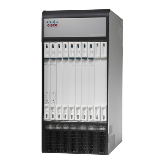
C H A P T E R ASR 5500 Hardware Platform Overview This chapter describes the hardware components that comprise the ASR 5500 chassis. The ASR 5500 is designed to provide subscriber management services for high-capacity 4G wireless networks. Figure 1: The ASR 5500 This chapter includes the following sections: •... -
Page 18: Chassis
The ASR 5500 is a 21RU, 19" rack-mount midplane-based chassis with input/output (I/O) and processing cards in the rear, and fabric cards in the front. Two ASR 5500 chassis fit into 42RU of rack space. However, the typical deployment will be a single chassis per rack with other equipment in the same rack. -
Page 19: Power
Cooling The ASR 5500 uses two types of fan tray units and a total of four fan trays per chassis – two front fan trays and two rear fan trays. Air is drawn from the front and sides of the chassis and exhausted out the top rear and sides. -
Page 20: Slot Numbering
11 through 20. Lower slot numbers begin at the left side. There are no direct relationships between front and rear cards. Figure 3: ASR 5500 Slot Numbering – MIO/UMIO Power Filter Units (PFUs) Two PFUs mount at the top front of the chassis. Each PFU supports four power planes. -
Page 21: Cable Management System
Cable Management System The ASR 5500 cable management system consists of two components. The first is a tray that mounts at the rear of the chassis immediately below the card cage. The second is a cable management bracket that mounts to the front panel of each Management Input/Output card (MIO/UMIO). -
Page 22: Card Types
Card Types Card Types The ASR 5500 supports rear cards and front cards. Rear cards are larger and perform node management, packet processing and I/O functions (traffic sources). Front cards determine the amount of bandwidth for the ASR 5500 Installation Guide... -
Page 23: Asr 5500 Installation Guide
ASR 5500 Hardware Platform Overview Card Types switching fabric (crossbars), and indicate the operating and alarm status of the ASR 5500. See the simplified block diagram below showing the ASR 5500 card architecture. Figure 5: Block Diagram of Card Architecture – MIO/UMIO Figure 6: ASR 5500 Card Types –... -
Page 24: Asr 5500 Installation Guide
ASR 5500 Hardware Platform Overview Card Types [LF] Management I/O (MIO) [LF] Data Processing Card (DPC) [RT] Management I/O Universal (UMIO) [RT] Data Processing Card Universal (UDPC) [LF] Data Processing Card 2 (DPC2) Fabric and Storage Card (FSC) [RT] Data Processing Card Universal 2... -
Page 25: Rear Cards
UDPC/UDPC2. Contact your Cisco account representative for additional information. Management I/O The ASR 5500 chassis supports two MIO /UMIO cards placed in the rear facing slots of the chassis. These cards perform chassis management, as well as local context and non-local context external I/O operations. -
Page 26: Data Processing Card
MIO/UMIO cards are shipped with SFP+ SR or LR transceivers installed. Data Processing Card The ASR 5500 chassis supports multiple DPCs/UDPCs in the rear facing slots of the chassis. The DPC/UDPC has two identical CPU subsystems with each containing: • Two six-core processors for a total of 24 cores per card •... -
Page 27: Front Cards
FSC. However, you must install four FSCs for normal operation. The ASR 5500 uses an array of solid state drives (SSDs) for short-term persistent storage. The RAID 5 configuration has each pair of drives on an FSC-200GB striped into a RAID 0 array; all the arrays are then grouped into a RAID 5 array. -
Page 28: System Status Card (Ssc)
The array appears under /hd-raid and is available to all data processing cards and MIO/UMIOs. System Status Card (SSC) The ASR 5500 chassis supports two SSCs in front facing slots of the chassis. SSCs use dedicated slots (11 and 12) on the front side of the chassis. -
Page 29: Led Indicators Common To All Cards
ASR 5500 Hardware Platform Overview LED Indicators Common to All Cards LED Indicators Common to All Cards Table 1: Base LED Group Label State Meaning Run/Fail Offline Green – Blink Transitioning Green – Solid Online Failure Active Not applicable Green – Blink Transitioning Green –... -
Page 30: Asr 5500 Installation Guide
ASR 5500 Hardware Platform Overview LED Indicators on Specific Cards Label State Meaning Activity No activity Green – Blink Data exchange Drive 1 Activity No activity Green Activity Drive 2 Activity No activity Green Activity System Status System offline Green... -
Page 31: Technical Specifications
Chassis Grounding, page 23 Physical Dimensions The ASR 5500 can be mounted in any standard (EIA-310-D, IEC 60297) 19-inch (482.6 mm) equipment cabinet or telecommunications rack. The table below lists the dimensions for the chassis and each component that can be placed within the chassis. -
Page 32: Environmental Specifications
5 Width on the pallet forks. 6 Without cable management bracket. Environmental Specifications The ASR 5500 is designed for deployment in unattended sites equipped with redundant power systems, redundant data communications connections, environmental controls (air conditioning, fire suppression), security devices and controlled access. -
Page 33: Environmental Standards
2 Within GR-63 limits for unattended operation. 3 Measured during GR-63 R4-97 testing. 4 Measured with DPC2 installed. Environmental Standards The ASR 5500 has been successfully tested for compliance with the environmental standards listed in table below. ASR 5500 Installation Guide... -
Page 34: Chassis Air Flow
Telecommunications Equipment Chassis Air Flow Air flow within the ASR 5500 complies with Telcordia recommendations to ensure vertical convection cooling of the system. As shown in the figure below, the lower fan trays pull ambient air inward from the front and side intake vents located near the bottom of the chassis. -
Page 35: Clearance
Ensure that the equipment rack or cabinet hardware does not hinder air flow at any of the intake or exhaust vents. Allow approximately 0.9 meter (36 inches) at the front and rear of the chassis for air flow and maintenance access. ASR 5500 Installation Guide... -
Page 36: Mounting Requirements
Figure 8: Rear Clearance Zone Mounting Requirements Each ASR 5500 chassis occupies 21 RU (rack units) within any standard (EIA-310-D, IEC 60297) 19-inch (482.6 mm) equipment rack or cabinet using the mounting brackets supplied with the chassis. Extension brackets (not supplied) may be used in conjunction with the chassis mounting brackets to install the chassis... -
Page 37: Power Requirements
This footprint does not include the rear-mounted cable management tray. Important Two ASR 5500 chassis fit in 42 RU (73.5 in.) of space within an equipment rack or cabinet. Rack mounting requires the use of industry-standard equipment racks or cabinets with Important supplier-recommended fasteners. -
Page 38: Example Power Calculations
All power inputs on PFU-A must be connected to live power feeds to assure that all chassis card slots are energized. 3 The type and number of cards installed in the ASR 5500 chassis determine the actual -48VDC power draw. Example Power Calculations, on page The power source must be a UL/CSA listed device with a regulated output no greater than -60VDC. -
Page 39: Central Office Alarm Interface
SSC Alarm Cabling chapter for details. Chassis Grounding The ASR 5500 is suitable for installation as part of the Common Bonding Network (CBN) within a network telecommunications facility. It is not intended for installation in an Isolated Bonding Network (IBN). -
Page 40: Asr 5500 Installation Guide
Technical Specifications Chassis Grounding ASR 5500 Installation Guide... -
Page 41: Installation Procedure Overview
C H A P T E R Installation Procedure Overview This chapter briefly describes the steps and tools that are required to install the ASR 5500 chassis. The copper serial Console port, 1000Base-T management ports, and CO alarm interface of the ASR 5500 Caution are suitable for connection to intra-building or unexposed wiring or cabling only. -
Page 42: Required Tools And Equipment
During installation, maintenance, and/or removal, wear a grounding wrist strap connected to the ASR 5500 chassis to avoid ESD damage to the components. Failure to do so could result in damage to sensitive electronic components and potentially void your warranty. ASR 5500 Installation Guide... -
Page 43: Equipment
MIO/UMIO cards for accessing the Command Line Interface (CLI). • Pallet jack and/or chassis lift to move and position the ASR 5500 chassis. Without such mechanical assistance, moving and positioning the chassis will require multiple craftpersons trained to safely handle heavy rack-mounted units. -
Page 44: Clearance
Clearance Clearance Adequate clearance must be maintained at the front and rear of the ASR 5500 chassis to assure proper air flow and allow maintenance access for the installation, removal and replacement of components. The recommended clearance is 36 inches (92 centimeters) at the front and rear of the chassis. -
Page 45: Standards Compliance
Installation Procedure Overview Standards Compliance Before the you can use the ESD jacks on the ASR 5500 chassis and its mounting brackets, you must first connect the chassis to ground according to the instructions in the Chassis Installation chapter of this document. -
Page 46: Ics Notice
Modifications to this product not authorized by Cisco could void the FCC approval and negate your authority to operate the product. -
Page 47: Chassis Installation
C H A P T E R Chassis Installation This chapter describes how to install the ASR 5500 chassis and its components. The ASR 5500 is suitable for installation in Network Telecommunication Facilities designed for unattended Important equipment operation. This chapter includes the following sections: •... -
Page 48: Weight Considerations
• When lifting any heavy object, remember to bend at the knees and lift with your legs. Bending at the waist and lifting with your back could cause personal injury. The ASR 5500 chassis is shipped with no circuit cards installed. Only the PFUs, fan trays and air filters Important are installed. -
Page 49: Unpack The Chassis
The straps that connect the packaging material are capable of inflicting damage to your skin or eyes if not handled properly. Step 1 Cut the straps that secure the cap and card board sleeve to the pallet. Remove the straps from the pallet and discard. ASR 5500 Installation Guide... -
Page 50: Asr 5500 Installation Guide
Chassis Installation Unpack the Chassis Container sleeve Pallet Strap Step 2 Remove the cardboard cap from the top of the container. ASR 5500 Installation Guide... -
Page 51: Reducing The Weight Of The Chassis Prior To Installation
Removing the Fan Trays To avoid personal injury and/or damage to the fan trays, be sure to support each fan tray's weight from Caution its front and rear as you slide it completely out of the chassis. ASR 5500 Installation Guide... -
Page 52: Remove The Upper Front Fan Tray
At the front of the chassis, remove the cover panel from the top of the chassis. Firmly grasp the side edges of the panel and pull up and away to unsnap the panel. Put the panel safely aside. Cover panel Access panel Front fan tray ASR 5500 Installation Guide... -
Page 53: Remove The Lower Front Fan Tray
Remove the Lower Rear Fan Tray Step 1 Remove the cover panel from the bottom of the chassis. Firmly grasp the side edges of the panel and pull down and away to unsnap the panel. Put the panel safely aside. ASR 5500 Installation Guide... -
Page 54: Asr 5500 Installation Guide
Chassis Installation Removing the Fan Trays Cover panel Access panel Rear fan tray ASR 5500 Installation Guide... -
Page 55: Removing The Pfus
Support the bottom of the fan tray unit with one hand as you pull it away from the chassis. Step 5 Place the fan tray unit safely aside. Removing the PFUs Step 1 Locate the left PFU bay (Power A) on the upper-left front of the chassis. ASR 5500 Installation Guide... -
Page 56: Installing The Chassis
Mounting the Chassis Flush Mount Step 1 Position the chassis in the equipment rack so that the flanges of the mounting brackets at the front of the chassis are flush with the mounting rails of the equipment rack. ASR 5500 Installation Guide... -
Page 57: Asr 5500 Installation Guide
Repeat step 1 and step 2 if you are installing an additional chassis in the equipment rack/cabinet. Step 4 If you took steps to reduce the weight of the chassis prior to installation, refer to Re-Installing Chassis Components, on page 45. Otherwise, proceed to Grounding the Chassis, on page ASR 5500 Installation Guide... -
Page 58: Mid Mount
Step 6 If you took steps to reduce the weight of the chassis prior to installation, refer to Re-Installing Chassis Components, on page 45. Otherwise, proceed to Grounding the Chassis, on page ASR 5500 Installation Guide... -
Page 59: Grounding The Chassis
Ground Cabling The ASR 5500 is suitable for installation as part of the Common Bonding Network (CBN) in a network Important telecommunications facility. It is not intended for installation in an Isolated Bonding Network (IBN). -
Page 60: Asr 5500 Installation Guide
Chassis Installation Ground Cabling Chassis ground point Grounding cable 2-hole lug Flat washer 7/16-inch Kep nut ASR 5500 Installation Guide... -
Page 61: Grounding Procedure
Use a Phillips #2 screwdriver to tighten each of the four screws on the PFU to secure it to the chassis. Step 5 Re-install the second PFU in the right bay (Power B) by repeating step 2 through step 4. ASR 5500 Installation Guide... -
Page 62: Re-Install The Front Fan Trays
With the unit resting on the bottom rail of the opening, slowly slide the fan tray into the chassis along the guides until it is seated firmly in the midplane connectors. Step 3 Reinstall the lower access cover. ASR 5500 Installation Guide... -
Page 63: Upper Rear Fan Tray
Push inwards to snap it in place. Cable Management System The ASR 5500 chassis ships with a cable management tray. This tray can be used in conjunction with cable management brackets that mount on the MIO/UMIO cards to route and secure network cables to interface ports. -
Page 64: Asr 5500 Installation Guide
Chassis Installation Cable Management System Refer to the Cable Management System Installation appendix for additional information. ASR 5500 Installation Guide... -
Page 65: Card Installation
C H A P T E R Card Installation This chapter describes how to install circuit cards and baffles in the ASR 5500 chassis. It includes the following sections: • Card Slot Assignments, page 49 • General Installation Sequence, page 51 •... -
Page 66: Asr 5500 Installation Guide
FSC-3 Required for all systems FSC-1 Required for all systems FSC-5 Available Reserved Reserved Table 8: ASR 5500 Chassis Card Slot Assignments (StarOS 18 and higher) Slot Card Sequence Requirement Rear of Chassis DPC-5 or UDPC-5 DPC2-5 or UDPC2-5 Available... -
Page 67: General Installation Sequence
Reserved General Installation Sequence Circuit cards and baffles are installed in the ASR 5500 chassis as follows: • Front circuit cards and baffles are installed from Right to Left. Start at slot 20 and continue to slot 11. Slots 19 and 20 always require baffles. -
Page 68: Card Interlock Switch
Card Interlock Switch Except for rear baffles, ASR 5500 cards include top and bottom ejector handles that incorporate hooks that fit behind the upper and lower rails of the card cage. Lifting the ejector handles outwards ejects the card from the midplane. -
Page 69: Circuit Cards
Figure 11: Card Ejector Handle Ejector handle Ejector subhandle (interlock) Captive screw (Phillips #2) Circuit Cards The installation procedure described below is identical for all circuit cards in the chassis. Circuit cards include: SSC, FSC, DPC/UDPC, DPC2/UDP2, MIO/UMIO. ASR 5500 Installation Guide... -
Page 70: Prerequisites
5500 chassis to avoid ESD damage to the components. Failure to do so could result in damage to sensitive electronic components and potentially void your warranty. Save several of the shipping cartons and ESD protective bags for use if a card must be returned to Cisco Important for fault analysis. -
Page 71: Baffles
Repeat step 1 through step 7 for every card you are installing at the rear and front of the chassis. Baffles Caution To ensure proper ventilation, baffles must be used in any chassis slot that is not occupied by a circuit card. ASR 5500 Installation Guide... - Page 72 Baffles consist of a blank front panel mounted to a formed metal baffle. The baffle slides into the card slots and provides a directed path for air flow. There are two types of baffles – front and rear. Figure 12: Front and Rear Baffles ASR 5500 Installation Guide...
-
Page 73: Installing A Front Baffle
Save several of the shipping cartons and protective ESD bags in which the circuit cards were packaged. Use the cartons to package a circuit card for shipment back to Cisco for failure analysis and replacement. For additional information, refer to the Returning Failed Components in the Replacing Components chapter, and the RMA Shipping Procedures appendix. - Page 74 Card Installation Save Shipping Cartons ASR 5500 Installation Guide...
-
Page 75: Chapter 6 Mio Port Cabling
The interface ports are selectively enabled based on their functions in the system – management versus non-management. Front Panel Ports MIO/UMIO cards in slot 5 and slot 6 of the ASR 5500 chassis support the following twisted-pair copper management interface ports: • one serial Console port (RJ45) •... -
Page 76: Daughter Card Ports
MIO/UMIO daughter cards support ten 10 Gigabit Ethernet ports each. The 10 GbE ports connect to other network devices via fiber optic cables that terminate on SFP+ transceivers. These ports support service traffic (non-management). Figure 13: MIO/UMIO Ports ASR 5500 Installation Guide... -
Page 77: Port Status Leds
Link/Act. LEDs - 1 GbE MGMT ports For the 10 GbE ports on each daughter card, the top two LEDs indicate Link status; the left/right arrows indicate for which port. The bottom two LEDs indicate Activity. ASR 5500 Installation Guide... -
Page 78: Cable Management System
(CLI). The interface communicates at 9600 to 115200 bps; the default is 115,200 bps. A connection to the Console port is required if you wish to view boot messages whenever the ASR 5500 Important chassis is powered up or rebooted. Only the Console port on the Master MIO or UMIO supports logs and CLI sessions. -
Page 79: Rj45 To Db9 Adapter
Table 10: Console RJ45 Cable to DB9Adapter Pinouts Signal Description Signal type RJ45 Pin DB9 Pin Not connected — Not connected — Receive Data (RX) Input Signal Ground (SGND) Ground Not connected — Transmit Data (TX) Output Not connected — Not connected — ASR 5500 Installation Guide... -
Page 80: Usb To Db9 Adapter
Transmit Data (TX) Output Data Terminal Ready (DTR) Output Unused Signal Ground (SGND) Ground Ground Data Set Ready (DSR) Input Unused Request To Send (RTS) Output Unused Clear To Send (CTS) Input Unused Ring Indicator (RI) Input Unused ASR 5500 Installation Guide... -
Page 81: Connect Console Port To Workstation
You can connect the terminal server to a serial port on a terminal server. The Console port does not support flow control signaling required by some types of terminal servers. Flow Important control must be disabled on the connected equipment. ASR 5500 Installation Guide... -
Page 82: Ethernet Management Stp Ports
• Stop Bits = 1 • Flow Control = None Important For additional information on connecting the Console port to Cisco servers equipped with asynchronous interface modules, refer to the Console Port to Cisco Server Cabling appendix. Ethernet Management STP Ports MIOs/UMIOs support two autosensing RJ45 10/100/1000Base-T (IEEE 802.3ab) Ethernet, shielded twisted-pair... -
Page 83: Rj45 Port Pinouts
The 10 Gigabit Ethernet ports on the daughter cards are only certified to work with SFP+ transceivers Caution tested and approved by Cisco. MIO and UMIO cards ship with SFP+ transceivers installed. The 10 Gigabit Ethernet ports accept the following fiber optic to electrical signal Small Form-Factor Pluggable... -
Page 84: Fiber Optic Bend Radius Guidelines
• 1 inch (2.54cm) under no pull load. • 2 inches (5.08cm) when subject to tensile loading up to the rated limit. For inside plant cable other than two- and four-fiber, the standard specifies: ASR 5500 Installation Guide... -
Page 85: Bend-Insensitive Multimode Fiber
An alternative for maintaining tighter than recommended bend radii is use of Bend-Insensitive Multimode Fiber (BIMMF). BIMMF is more impervious to bend loss than standard 50-micron multimode fiber (MMF) cable. BIMMF cables are only optimized for 850nm wavelengths and not for 1300nm wavelengths. Important ASR 5500 Installation Guide... -
Page 86: Fiber Optical Connections
Attach the other end of the network fiber-optic cable to the network device that you want to connect. Step 5 Repeat Step 1 through Step 4 for the remaining ports on the daughter card. Step 6 Repeat Step 1 through Step 4 for ports on the second DC. ASR 5500 Installation Guide... -
Page 87: Cleaning Fiber Optic Connectors
If you detect any contamination, repeat Steps 1 and 2. Caution Because invisible laser radiation may be emitted from the aperture of the port when no cable is connected, avoid exposure to laser radiation and do not stare into open apertures. ASR 5500 Installation Guide... - Page 88 MIO Port Cabling Cleaning Fiber Optic Connectors ASR 5500 Installation Guide...
-
Page 89: Ssc Alarm Cabling
• Major Alarm – This alarm is triggered when there is a: • Hardware failure that causes the card to be placed in an off-line state • PFU failure or removal from the chassis ASR 5500 Installation Guide... -
Page 90: Alarm Cutoff (Aco)
Alarm Cutoff (ACO) The front panel of the SSC includes an audible system alarm and an Alarm Cutoff (ACO) switch. Press and release this switch to reset the system alarm speaker. Figure 19: SSC CO Alarm Interface ASR 5500 Installation Guide... -
Page 91: Alarm Connector Pinout
— Not connected Major Major, Common — Not connected — Not connected Critical Critical, Common Electrical Characteristics Each of the three dry-contact, Form C relay switches is rated to support a maximum switching current of 1A@30VDC. ASR 5500 Installation Guide... -
Page 92: Co Alarm Wiring Example
With all relays de-energized, the green LEDs are illuminated. If an alarm relay is energized, its NO (normally open) contact closes; the green LED is extinguished and the red LED is illuminated. Figure 20: CO Alarm Interface Schematic ASR 5500 Installation Guide... -
Page 93: Power Cabling
Typically, the DC power feeds are fed from a power distribution frame (PDF) to a power distribution panel (PDP) at the rack. The DC power Battery Return (BR) or positive terminal, must be grounded at the source end (power feed Important or mains power end). ASR 5500 Installation Guide... -
Page 94: Internal Power Planes
The circuit breakers at the power distribution panel must disconnect the supply line of each -48VDC feed. However, it is recommended that the circuit breakers at the power distribution panel simultaneously disconnect both poles (supply and return) for each -48 VDC feed to completely isolate the ASR 5500 from the power source. -
Page 95: Chassis Power Card Slot Allocations
— UDPC2 Front Cards — — — — — — — — — — — — — — — — — — — — — — — — Reserved — — — Reserved — — — ASR 5500 Installation Guide... -
Page 96: Power Feed Connections
The figure below shows a recommended method for connecting -48 VDC power feeds from the power distribution frame (PDF) through a power distribution panel (PDP) to the power filter units (PFUs) on the ASR 5500 chassis. ASR 5500 Installation Guide... -
Page 97: Power Cable Requirements
• Each conductor between the PDF and PDP should be calculated assuming a 0.3 volt drop from the PDF to the panel. • Each cable between the PDP and ASR 5500 PFUs should be calculated a 0.3 volt drop from the panel to the chassis. This is a total voltage drop of 0.6 volts. -
Page 98: Terminating Power Cables
Power Cabling Terminating Power Cables Even if the ASR 5500 chassis will not be completely filled with cards, size the cables for maximum power Important draw according to the above recommendations. This practice facilitates future expansion as more cards are added and the power supply is appropriately incremented. -
Page 99: Connect Power Feeds To The Pfus
Connect Power Feeds to the PFUs Connect Power Feeds to the PFUs To avoid personal injury or possible equipment damage, ensure that the circuit breakers for all ASR 5500 Caution chassis feeds from the power distribution panel are all set to OFF before attempting to attach power cables to the PFU(s). - Page 100 Step 1 Remove the plastic power input cover from the top-rear of the ASR 5500 chassis. Use a Phillips #2 head screw driver to loosen the two captive screws securing the cover to the chassis. Removing this cover exposes the power feed terminals at the rear of the PFUs.
- Page 101 Step 12 Proceed to the System Power-up chapter for information and instructions on applying power to the chassis and verifying that the installation was successful. Figure 24: PFU Rear Power Connections Power input cover Insulating spacer ASR 5500 Installation Guide...
- Page 102 Power Cabling Connect Power Feeds to the PFUs 2-hole, 90 Flat washer Lock washer 7/16-inch hex nut Non-conductive wrap -48VDC Supply cable -48VDC return cable Cable access opening ASR 5500 Installation Guide...
-
Page 103: System Power-Up
The standby MIO/UMIO observes the active card's startup. If the file on the active card is loading normally, the standby MIO/UMIO boots from the active card's image. If the active MIO/UMIO experiences a problem during this phase, the ASR 5500 Installation Guide... -
Page 104: Applying Power To The Chassis
Turn ON all the circuit breakers on both PFUs. Step 7 Proceed to Verifying System Startup, on page Step 8 When the initial checks are completed, reinstall the covers removed in step 1 and step 4. ASR 5500 Installation Guide... -
Page 105: Verifying System Startup
Checking Status LEDs on MIOs The table below identifies the operational and transitional states for LED indicators on an MIO /UMIO card. Table 16: MIO/UMIO/ Operating States and Status LED Indicators Label LED Color LED State Notes Card Transition ASR 5500 Installation Guide... - Page 106 Card Active – Secondary (Normal) Run/Fail Green Card is online and functioning as a Slave. Any port can be active. Active Green All ports are backed up by other MIO/UMIO. Redundant Green Master — Busy — Card Active – Secondary ASR 5500 Installation Guide...
- Page 107 — Port Status Port – Link Green Port is in active mode. Amber Port is in standby mode. — Port is down. Port Activity Green Blink Data is being sent/received. — Data is not being sent/received. ASR 5500 Installation Guide...
-
Page 108: Checking Status Leds On Data Processing Cards
Card Migrate Run/Fail Green Card is online and migrating from or to other DPC/UDPC or DPC2/UDPC2. Active Green Blink Redundant Amber Card Failed Run/Fail Card has failed and is offline. Active — Redundant — Card Offline ASR 5500 Installation Guide... -
Page 109: Checking Status Leds On Fscs
SSD 2 is being accessed. Card Active Run/Fail Green Non-redundant switch fabric Non-redundant storage Active Green Redundant Amber Drive 1 Active Green Blink SSD 1 is being accessed. Drive 2 Active Green Blink SSD 2 is being accessed. Card Failed ASR 5500 Installation Guide... -
Page 110: Checking Status Leds On Ssc
Redundant — Card Active (Normal) Run/Fail Green Card is backed up by other SSC. Active Green Redundant Green Card Active Run/Fail Green Card is not backed up by other SSC. Active Green Redundant Amber Card Failed ASR 5500 Installation Guide... -
Page 111: Show Leds Command
There are no failed components. Offline or Transitioning System Status — SSC is offline. System Service — show leds Command The show leds command displays the current operating state (color) of the status LEDs of all cards in the system. ASR 5500 Installation Guide... - Page 112 System Power-up show leds Command ASR 5500 Installation Guide...
-
Page 113: Initial System Configuration
Additional Configuration Tasks, page 112 Basic Configuration After power is applied to the chassis and the ASR 5500 has successfully booted, the command line interface (CLI) appears on a terminal connected to the Console port of the Master MIO. The initial configuration requires completing the following tasks via the CLI: •... -
Page 114: Context-Level Security Administrator And Hostname
Specifies that the security administrator is allowed to access the system with the File Transfer Protocol (FTP). This option is useful to upload files (configuration or software images). Note: In release 20.0 and higher Trusted StarOS builds, FTP is disabled. ASR 5500 Installation Guide... -
Page 115: Mio/Umio Port Numbering
For lab environments where network booting of the chassis is desirable, Ethernet 1 port on an MIO/UMIO Important can be used to network boot the chassis. Other MIO/UMIO ports cannot be used for network booting. The MIO/UMIO is equipped with two daughter cards (DCs). Each DC supports ten 10 GbE ports. ASR 5500 Installation Guide... -
Page 116: Configure The Ethernet Management Interface
For example, the address of the loopback interface, usually assigned the host name localhost, is 127.0.0.1. It consists of the four binary octets 01111111, 00000000, 00000000, and 00000001, forming the full 32-bit address. IPv4 allows 32 bits for an Internet Protocol address and can, therefore, support 2 (4,294,967,296) addresses. ASR 5500 Installation Guide... -
Page 117: Ipv6 Colon-Separated-Hexadecimal Notation
The number of addresses of a subnet defined by the mask or prefix can be calculated as 2 , in 32-29 which the address size for IPv4 is 32 and for IPv6 is 128. For example, in IPv4, a mask of /29 gives: 2 = 8 addresses. ASR 5500 Installation Guide... -
Page 118: Configuring The Ethernet Management Interface
IPv6 colon-separated-hexadecimal format). interface_name specifies the name of the interface that was configured in Step 2. Refer to the System Administration Guide for additional information. Step 7 Enter exit at the prompt to exit the context configuration mode. The following prompt appears: exit [local]host_name(config-ctx)# [local]host_name(config)# ASR 5500 Installation Guide... - Page 119 Step 11 Enter exit to exit the Ethernet Interface Configuration mode. slot/port exit [local]host_name(config-port- [local]host_name(config)# ASR 5500 Installation Guide...
-
Page 120: Configuring The Management Interface With A Second Ip Address
(LAN) or wide area network (WAN) via the following communication protocols: • Telnet • Secure Shell (SSH • File Transfer Protocol (FTP) (secured or unsecured) • Trivial File Transfer Protocol (TFTP) ASR 5500 Installation Guide... - Page 121 For maximum system security, you should not enable FTP. In release 20.0 and higher Trusted StarOS Important builds, FTP is not supported server ftpd [local]host_name(config-ctx)# Step 7 Enter server tftpd to allow TFTP access. server tftpd [local]host_name(config-ctx)# Step 8 Enter exit to exit the context configuration mode. exit [local]host_name(config-ctx)# [local]host_name(config)# ASR 5500 Installation Guide...
-
Page 122: Configuring Ssh Options
Specify the bit size for SSH keys. host_name ssh key-size { 2048 | 3072 | 4096 | 5120 | 6144 | 7168 | 9216 } [local] (config)# The default bit size for SSH keys is 2048 bits. ASR 5500 Installation Guide... -
Page 123: Generating Ssh Keys
• type specifies the key type; v2-rsa is the only supported type. For releases prior to 20.0, StarOS supports a maximum of 64 configurable authorized SSH keys. For Important release 20.0 and higher, StarOS supports a maximum of 200 configurable authorized SSH keys. ASR 5500 Installation Guide... -
Page 124: Specifying Ssh Encryption Ciphers
• aes256-gcm@openssh.com – AES, 256-bit key size, GCM, OpenSSH • chacha20-poly1305@openssh.com – ChaCha20 symmetric cipher, Poly1305 cryptographic Message Authentication Code [MAC], OpenSSH The default string for algorithm is: blowfish-cbc,3des-cbc,aes128-cbc,aes128-ctr,aes192-ctr,aes256-ctr,aes128-gcm@openssh.com, aes256-gcm@openssh.com,chacha20-poly1305@openssh.com Step 3 Exit the SSH Configuration mode. host_name [local] (config-sshd)# host_name [local] ASR 5500 Installation Guide... -
Page 125: Set System Timing
Wednesday October 10 13:08:27 us-eastern 2012 Configuring Network Time Protocol Support This section describes how to enable the use of the Network Time Protocol (NTP) on the ASR 5500 chassis. Overview of NTP Support Many of the services offered by the ASR 5500 platform require accurate timekeeping derived through NTP. -
Page 126: Basic Ntp Configuration
Use of prefer usually results in a poorer choice than NTP can determine for itself. Important Do not change the maxpoll, minpoll, or version keyword settings unless instructed to do so by Cisco TAC. Basic NTP Configuration Configure the system clock and time zone prior to implementing NTP support. -
Page 127: Using A Load Balancer
Last reported NTP reference to which the server is synchronizing. NTP server stratum level. Communication type: broadcast, multicast, etc. when Number of seconds since the last contact. poll Polling interval between the system and the NTP server. ASR 5500 Installation Guide... -
Page 128: Enable Cli Timestamping
This completes the basic configuration process. Additional Configuration Tasks Establishing the basic configuration allows an operator to access the ASR 5500 for management purposes. Additional configuration settings are required for full operational deployment within a provider network. To complete these tasks, refer to the following documents: •... - Page 129 Initial System Configuration Additional Configuration Tasks • Administration Guide specific to the type of product being deployed. • StarOS Release Notes ASR 5500 Installation Guide...
- Page 130 Initial System Configuration Additional Configuration Tasks ASR 5500 Installation Guide...
-
Page 131: System Monitoring
There is no limit to the frequency that any of the individual commands or procedures can be implemented. Daily - Standard Health Check The standard health check is divided into independent procedures: • Hardware Status • Physical Layer Status • System Status and Performance ASR 5500 Installation Guide... - Page 132 Review session statistics, such as connects, rejects, hand-offs, show session counters historical collected in 15-minute intervals. View duration, statistics, and state for active call sessions. show session duration show session progress show session summary ASR 5500 Installation Guide...
-
Page 133: Periodic Status Checks
Depending upon system usage and performance, you may want to perform these tasks more frequently than recommended. Table 23: Periodic Status Checks To do this: Enter this command: Monthly Check for unused or unneeded files on /flash. dir /flash ASR 5500 Installation Guide... -
Page 134: Counters And Bulkstats
Replacing the Chassis Air Filter section of this guide for detailed instructions. Counters and Bulkstats The ASR 5500 maintains many counters for gathering statistics and troubleshooting. In general you should not regularly clear the counters, just let them increment over time. Counters track events since the chassis booted (unless cleared), unlike show commands that give the current state (for example, the current number of calls). -
Page 135: Summary Of Maintenance Tasks
• Watch SNMP traps for alarms/thresholds and take appropriate action. The traps inform you of serious problems that can occur on the system, including those that do not involve the ASR 5500. • If you have an Element Management System (EMS) server that relies on bulkstats and other data, pay attention to alarms and call load. -
Page 136: Monthly
• If the boot system priority is approaching a low value, reset it to a higher priority. • When you finish troubleshooting with runtime logging, remove the logging commands from the config. • Maintain your SNMP trap server. • Maintain your syslog server. ASR 5500 Installation Guide... -
Page 137: C H A P T E
One possible indication that air filters need to be replaced is if the chassis temperature remains high for extended periods of time. This condition causes the multi-speed fans to run at high speed. Clogged and dirty air filters could hinder air flow through the chassis and result in higher operating temperatures. ASR 5500 Installation Guide... -
Page 138: Temperature And Fan Alarm Commands
Do not attempt to install air filters in the space above the upper fan trays. The top of the chassis is not Caution designed for air filters. Installing air filters above the upper fan trays may cause power shorts. ASR 5500 Installation Guide... -
Page 139: Front Air Filter
The plastic tabs should be hanging down. Step 8 Reinstall the fan tray access cover. Step 9 Reinstall the chassis cover panel by snapping it in place. Step 10 Discard the old air filter. Figure 25: Front Air Filter Location ASR 5500 Installation Guide... - Page 140 Replaceable Components Replacing an Air Filter Cover panel Access Cover Front air filter (ASR55-FLTR-AIR-F=) Pull tab ASR 5500 Installation Guide...
-
Page 141: Rear Air Filter
Verify that the arrows located on the sides of the replacement air filter point upwards (metal grid facing up). These arrows indicate the direction of the airflow into the chassis through the filter. The spring indicates the rear of the filter and goes toward the midplane. ASR 5500 Installation Guide... - Page 142 The plastic tabs should be hanging down. Step 7 Reinstall the fan tray access cover. Step 8 Reinstall the chassis cover panel by snapping it in place. Step 9 Discard the old air filter. Figure 26: Rear Air Filter Location ASR 5500 Installation Guide...
-
Page 143: Fan Tray Units
(5 cm). Wait a few seconds to allow fans to spin down before fully removing the fan tray. ASR 5500 Installation Guide... - Page 144 Replaceable Components Replacing Front Fan Trays Have the replacement fan tray available and ready to be installed before starting the replacement procedure. Important ASR 5500 Installation Guide...
-
Page 145: Replace The Upper Fan Tray
Step 7 Slowly slide the fan tray into the chassis along the guides until the rear connector is firmly seated in the midplane. If the ASR 5500 is powered up, the fans should begin spinning. Step 8 Tighten the screws that secure the fan tray to the chassis. - Page 146 Replaceable Components Replacing Front Fan Trays Cover panel Access Cover Front fan tray ASR 5500 Installation Guide...
-
Page 147: Replace The Lower Fan Tray
Align the replacement fan tray within the lower chassis opening. With the unit resting on the bottom rail of the opening, push inward until it is firmly seated in the rear connectors. If the ASR 5500 is powered up, the fans should begin spinning. -
Page 148: Replace The Upper Fan Tray
Align the replacement fan tray within the upper chassis opening. With the unit resting on the bottom rail of the opening, push inward until the rear connector is firmly seated in the midplane. If the ASR 5500 is powered up, the fans should begin spinning. -
Page 149: Replace The Lower Fan Tray
Align the replacement fan tray within the lower chassis opening. With the unit resting on the bottom rail of the opening, push inward until the rear connector is firmly seated in the midplane. If the ASR 5500 is powered up, the fans should begin spinning. - Page 150 Replaceable Components Replacing Rear Fan Trays Cover panel Access Cover Rear fan tray ASR 5500 Installation Guide...
-
Page 151: Pfu
Loosen the screws and remove the plastic terminal cover. b) Use a 7/16-inch nut driver or socket wrench to remove the nuts, lock washers and flat washers from each of the eight terminals and set them aside for reuse. ASR 5500 Installation Guide... - Page 152 LEDs should be ON. Step 13 Reinstall the plastic terminal cover on the top-rear of the chassis. To avoid the risk of personal injury and/or potential damage to the system, never operate the chassis without Caution the plastic cover. ASR 5500 Installation Guide...
-
Page 153: Circuit Cards
Reinstall the front top cover panel by aligning it over the balled posts and snapping it in place. Step 15 For additional instructions, refer to Returning Failed Components, on page 147. Figure 29: PFU Replacement Cover panel Circuit Cards This section describes how to replace circuit cards in the ASR 5500 chassis. ASR 5500 Installation Guide... -
Page 154: Determining Whether A Card Has Failed
Determining Whether a Card has Failed The ASR 5500 has several ways to indicate an application card failure. The first indicator is that the Status LED on the System Status Card (SSC) turns red to indicate the failure of a chassis component. Another indicator is the Run/Fail LED on an application card is red or turns off if that card has a problem. -
Page 155: Snmp Traps
Airflow: Lower Middle : 0 FPM SNMP Traps The ASR 5500 supports SNMP traps that are triggered when conditions indicate status changes on application cards. To display SNMP trap statistics, run the show snmp trap statistics command. A sample output appears below. -
Page 156: Backing Up The System Configuration
Important An FSC-200GB (equipped with two 200GB SSDs) can be replaced with an FSC-400GB (equipped with a single 400GB SSD) only if the StarOS release supports the non-RAID 0 configuration of the FSC-400GB. ASR 5500 Installation Guide... -
Page 157: Replacing A Failed Card
Replacing a Failed Card This section describes how to remove and replace a failed circuit card. Circuit cards can be replaced while the ASR 5500 is operating. Important The optical SFP+ interfaces on the MIO/UMIO comply with the limits for Class 1 laser devices for IEC825, Important EN60825, and 21CFR1040 specifications. -
Page 158: Remove I/O Connections (Mio/Umio And Ssc)
MIO or UMIO Important If your ASR 5500 chassis is equipped with a cable management system, refer to the special instructions for Detaching Network Cables from the Card Bracket in the Cable Management System Installation appendix. Step 1 Unplug the cable connected to the RJ45 serial Console port. - Page 159 146. Important If your ASR 5500 chassis is equipped with a cable management system, refer to the special instructions for Reconnecting Network Cables to the Card Bracket and Raising the Cable Management Tray in the Cable Management System Installation appendix.
-
Page 160: Swapping The Sdhc Memory Card
Phillips #2 Screw Ejector handle Ejector subhandle Swapping the SDHC Memory Card The SDHC memory card on the MIO/UMIO appears as the /flash drive on the CLI. The /flash drive stores configuration data, including the boot priority settings. ASR 5500 Installation Guide... - Page 161 ESD precautions when handling the SDHC card and MIO/UMIO cards. Step 1 On a failed MIO/UMIO, locate the SDHC card in the bottom rear corner of the circuit card (see figure below). Figure 31: MIO/UMIO SDHC Card Location ASR 5500 Installation Guide...
-
Page 162: Cleaning Fiber Optic Connectors
On the replacement MIO/UMIO, locate the SDHC card holder and remove the SDHC card. That card contains only a basic configuration for testing purposes; insert it into the failed card prior to returning the circuit card to Cisco. Step 4 On the replacement MIO/UMIO, insert the SDHC card removed from the failed MIO/UMIO. -
Page 163: Returning Failed Components
If the failed component is still under Cisco warranty or a hardware maintenance contract, return it for repair or replacement. If the failed component is out of warranty or not covered by a maintenance contract, contact Cisco to determine if it can be sent in for repair at an additional cost. - Page 164 Replaceable Components Returning Failed Components ASR 5500 Installation Guide...
-
Page 165: Appendix A Spare Component Recommendations
This appendix provides a recommended quantity of spare components to be stocked as part of a sparing program for the ASR 5500. This information should only be used as a guideline for designing a sparing program that meets your company's design, deployment, and availability goals. - Page 166 6 Direct replacement for DPC; requires U-PID license per installed UDPC. See Chassis Universal License Requirements for additional information. 7 The DPC2/UDPC2 is not interchangeable with a DPC/UDPC. 8 Direct replacement for DPC2; requires U-PID license per installed UDPC2. See Chassis Universal License Requirements for additional information. ASR 5500 Installation Guide...
-
Page 167: Appendix B Chassis Universal License Requirements
(UMIO) and Data Processing Universal (UDPC/UDPC2) card types. It also explores UMIO and UDPC/UDPC2 behavior in non-universal chassis or in chassis with a mix of non-universal MIOs and DPC/DPC2s, and UMIOs and UDPC/UDPC2s. Contact your Cisco account representative for detailed information regarding ASR 5500 license Important requirements. -
Page 168: Staros License Support Matrices
Chassis Universal License Requirements StarOS License Support Matrices To add one or more UDPC/UDPC2 to an ASR 5500 chassis where the numbered of allowed UDPC/UDPC2s has been reached, you must update the chassis license to increase the number of supported cards. See... -
Page 169: Updating A Chassis License For Universal Cards
Standby MIO become Active. Updating A Chassis License for Universal Cards This section describes how to update the chassis license. Do NOT install the additional UDPC/UDPC2s until the chassis license has been updated as described Important below. ASR 5500 Installation Guide... - Page 170 Updating A Chassis License for Universal Cards You do not have to shut down or reboot the ASR 5500 to update the chassis license or install the additional UDPCs. However, if you install the additional UDPC/UDPC2s and they boot under the old chassis license, they will not come into service.
-
Page 171: Appendix C Cable Management System Installation
CMS Procedure for Replacing ASR 5500 Circuit Cards, page 164 Introduction The ASR 5500 cable management system consists of two components. The first is a tray that mounts at the rear of the chassis immediately below the card cage. The second is a cable management bracket that mounts to the faceplate of each MIO/UMIO card. - Page 172 Use the supplied 3/32 in. Allen hex wrench to tighten the shoulder screw. The screw should be tightened to 6 in-lb (0.68 N-m). Do not overtighten the shoulder screw or the swing arm will Important bind. ASR 5500 Installation Guide...
- Page 173 Installing the Cable Management Tray Step 6 Repeat Step 3 through Step 5 to secure the other swing arm. Figure 32: Installing the Cable Management Tray Cable management tray Swing arm Shoulder screw Nylon washer Latch Hook-and-loop strap ASR 5500 Installation Guide...
- Page 174 Removing Cable Guides, on page 159. You must install the cable management bracket on each MIO/UMIO card before you can route and secure network cables. For additional information, refer to Installing Cable Management Brackets, on page 160. ASR 5500 Installation Guide...
-
Page 175: Removing Cable Guides
Locate and remove the screws and washers. Step 8 Repeat Step 1 through Step 7 for the middle guide of the other group of three guides. Figure 34: Removing Cable Guides Cable management tray Cable guide Phillips #1 screwdriver ASR 5500 Installation Guide... -
Page 176: Installing Cable Management Brackets
The cable management bracket is packaged in the MIO/UMIO shipping box. Ideally, the bracket should be installed on an MIO/UMIO before it is installed in the ASR 5500 chassis. However, you can safely install the bracket on an MIO/UMIO in a powered-up ASR 5500 chassis. - Page 177 Cable Management System Installation MIO/UMIO Cards Figure 35: Installing Cable Management Bracket - MIO/UMIO Card MIO/UMIO faceplate Cable management bracket Nylon sleeve Nylon pin ASR 5500 Installation Guide...
-
Page 178: Securing Cables
Routing and Securing Network Cables Important This procedure assumes that the cable management tray has been installed on the ASR 5500 chassis, and cable management brackets have been installed on the MIO/UMIO cards. The general procedure for using the CMS is to route network cables through either end of the cable management tray upwards toward the cable management brackets on the MIO/UMIOs. - Page 179 If necessary increase the slack in a bundle to avoid damaging the cables. The figure and table below show the recommended sequence for routing cables to the MIO/UMIOs in slots 5 and 6. Figure 36: CMS Cable Routing ASR 5500 Installation Guide...
-
Page 180: Cms Procedure For Replacing Asr 5500 Circuit Cards
CMS Procedure for Replacing ASR 5500 Circuit Cards When the cable management tray is installed, the procedure for removing circuit cards from the ASR 5500 chassis varies from that described in the Circuit Cards section of the Replaceable Components chapter. -
Page 181: Lowering The Cable Management Tray
Management Brackets, on page 160 Step 2 Route the cables and secure them to the bracket as described in Routing and Securing Network Cables, on page 162 Step 3 Proceed to Raising the Cable Management Tray, on page 166 ASR 5500 Installation Guide... -
Page 182: Raising The Cable Management Tray
Verify that the cable tray can be lifted upward and secured without pinching any of the network cables. If necessary increase the slack in a bundle to avoid damaging the cables. Step 3 Flip the latches on the swing arms up and over the posts to secure the tray to the chassis. ASR 5500 Installation Guide... -
Page 183: Appendix D Console Port To Cisco Server Cabling
Configuration, page 169 Introduction Cisco communication servers and routers can be equipped with asynchronous interface modules as shown in the table below. These modules accept one of two types of serial RJ45 "octopus" cables: • CAB-HD8-ASYNC – uses a single high-densityVHDC168M connector at the interface module end, •... -
Page 184: Cabling
Cabling The figure and table below indicate how the MIO/UMIO Console port connects to an interface module via the asynchronous RJ45 adapter cable and a Cisco rollover cable or coupler. Figure 37: SR 5500 Console to Cisco CAB Assembly Cabling... -
Page 185: Configuration
Console Port to Cisco Server Cabling Configuration Configuration The MIO/UMIO facing interface of the Cisco server should be configured via IOS as shown in the following example: line 0/0/0 0/0/14 exec-timeout 0 0 no exec transport input all speed 115200 For detailed information, refer to the Configuration guides supplied with the Cisco device and asynchronous interface module. - Page 186 Console Port to Cisco Server Cabling Configuration ASR 5500 Installation Guide...
-
Page 187: Rma Shipping Procedures
The following general guidelines apply when packaging components: • It is best to use the original Cisco box and packaging in which your equipment was sent and received. You can use a shipping carton saved when the system and its components were installed. You can also use the packaging for a replacement component to repackage the original component. -
Page 188: Re-Packaging Your Rma
If using the original Cisco box and packaging, properly place the item within the packaging material. If using a non-Cisco shipping carton and packing material, be sure the item is properly surrounded with bubble wrap or packaging foam to ensure restriction in movement during transport. -
Page 189: Cisco Return Locations
Cisco Return Locations Cisco Return Locations For a list of authorized Cisco return centers, go to the Authorized Return Locations link on www.cisco.com. Packaging ASR 5500 Cards This section provides detailed instructions for packaging ASR 5500 front and rear cards using Cisco shipping cartons. -
Page 190: Rear Cards
• Data Processing Card v2 (DPC2) or Data Processing Universal v2 (UDPC2) Rear cards use the larger ESD bags and shipping cartons. There are very slight differences in the cutouts Important at the rear of the MIO/UMIO, DPC/DPC2 or UDPC/UDPC2 foam. ASR 5500 Installation Guide... - Page 191 Step 4 Close the carton and seal it with shipping tape. See Sealing the Shipment, on page 172. Step 5 Place the shipping label on the outside of the carton. See Labeling the Shipment, on page 172. ASR 5500 Installation Guide...
- Page 192 RMA Shipping Procedures Rear Cards ASR 5500 Installation Guide...