Keithley DMM7510 Calibration Manual
7 1/2 digit graphical sampling multimeter
Hide thumbs
Also See for DMM7510:
- Reference manual (1036 pages) ,
- Calibration manual (107 pages) ,
- User manual (96 pages)

Related Manuals for Keithley DMM7510


Summary of Contents for Keithley DMM7510
- Page 1 Model DMM7510 7½ Digit Graphical Sampling Multimeter Calibration Manual DMM7510-905-01 Rev. A / March 2015 *PDMM751090501A* DMM7510-905-01A A Great er Me a s ure of C on f i de nc e...
- Page 2 , and TSP-Net are trademarks of Keithley Instruments, Inc. All Keithley Instruments product names are trademarks or registered trademarks of Keithley Instruments. Other brand names are trademarks or registered trademarks of their respective holders. The Lua 5.0 software and associated documentation files are copyright © 1994-2008, Tecgraf, PUC-Rio.
-
Page 4: Safety Precautions
Keithley Instruments products are designed for use with electrical signals that are measurement, control, and data I/O connections, with low transient overvoltages, and must not be directly connected to mains voltage or to voltage sources with high transient overvoltages. - Page 5 (note that selected parts should be purchased only through Keithley Instruments to maintain accuracy and functionality of the product). If you are unsure about the applicability of a replacement component, call a Keithley Instruments office for information.
-
Page 6: Table Of Contents
Table of Contents Introduction ....................... 1-1 Welcome ..........................1-1 Introduction to this manual ....................1-1 Extended warranty ....................... 1-2 Contact information ......................1-2 Performance verification ..................2-1 Introduction .......................... 2-1 Factory service ........................2-2 Verification test requirements ....................2-2 Environmental conditions ......................2-2 Warmup period .......................... - Page 7 Table of Contents Model DMM7510 7½ Digit Graphical Sampling Multimeter Calibration Manual Environmental conditions ..................... 3-1 Temperature and relative humidity .................... 3-1 Line power..........................3-2 Warmup period ........................3-2 Calibration considerations ....................3-2 Calibration cycle ........................3-3 Recommended test equipment ....................3-3 Instrument setup ........................
-
Page 8: Introduction
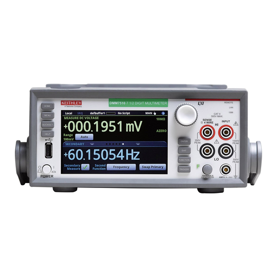
Contact information ..............1-2 Welcome Thank you for choosing a Keithley Instruments product. The Model DMM7510 is a 7½ digit graphical sampling multimeter that expands standard DMM functions with high-speed digitizing and large graphical color touchscreen display. This DMM offers a broad range of measurement capabilities, including 17 measurement functions. -
Page 9: Extended Warranty
If you have any questions after you review the information in this documentation, please contact your local Keithley Instruments office, sales partner, or distributor. You can also call Keithley Instruments corporate headquarters (toll-free inside the U.S. and Canada only) at 1-800-935-5595, or from outside the U.S. -
Page 10: Performance Verification
Rear-panel verification ............2-63 Introduction Use the procedures in this section to verify that Model DMM7510 accuracy is within the limits stated in the instrument’s one-year accuracy specifications. Specifications and characteristics are subject to change without notice; please refer to the Keithley website (http://www.keithley.com) for the most... -
Page 11: Factory Service
Also, allow the test equipment to warm up for the minimum time specified by the manufacturer. Line power The Model DMM7510 requires a line voltage of 100 V to 240 V and a line frequency of 50 Hz or 60 Hz. Verification tests should be performed within this range. -
Page 12: Recommended Test Equipment
Test equipment uncertainty adds to the uncertainty of each measurement. Generally, test equipment uncertainty should be at least four times more accurate than corresponding Model DMM7510 specifications. The following table lists the uncertainties of the recommended test equipment. -
Page 13: Auto Calibration
Automatic calibration removes measurement errors that are caused by the performance drift on the components used in the DMM as a result of temperature and time. Auto calibration improves short- term accuracy of the Model DMM7510. However, you must still perform regular full calibration with metrology equipment to maintain overall accuracy. -
Page 14: Scheduling Auto Calibration
You can set up your instrument to run auto calibration automatically. You can also set up the instrument to prompt you to run auto calibration at regular intervals. To determine the best schedule for your application, see the Model DMM7510 specifications for detail on the accuracy with and without auto calibration. -
Page 15: Reviewing Calibration Information
Section 2: Performance verification Model DMM7510 7½ Digit Graphical Sampling Multimeter Calibration Manual From the front panel: 1. Press the MENU key. 2. Under System, select Calibration. 3. Select Scheduling Action. To have the instrument: Prompt you to run auto calibration: Select Notify. -
Page 16: Monitoring Internal Temperature
Model DMM7510 7½ Digit Graphical Sampling Multimeter Calibration Manual Section 2: Performance verification Monitoring internal temperature You can monitor the temperature difference between the actual internal temperature and the temperature when auto calibration ran through the panel or by using remote commands. With remote commands, you can also check the present internal temperature and the internal temperature when auto calibration was last run. -
Page 17: Verification Limits
Example reading limit calculation Assume you are testing the 10 VDC range using a 10 V input value. Using the Model DMM7510 one-year accuracy specification for 10 VDC of ± (14 ppm of reading + 1.2 ppm of range), the calculated limits are: Reading limits = 10 V ±... -
Page 18: Performing The Verification Test Procedures
(on page 2-66) • AC current 10 A verification (on page 2-67) If the Model DMM7510 is not within specifications and is not under warranty, see the calibration procedures in Calibration (on page 3-1) for information about calibrating the unit. -
Page 19: Front-Panel Verification
Be sure the test equipment is set up for the proper function and range. • Do not connect test equipment to the Model DMM7510 through a scanner, multiplexer, or other switching equipment. Ensure Auto Calibration has been performed with 30 days and that the Temperature Difference is less than ±5 °C. - Page 20 Verify the DC voltage 100 mV range (on page 2-12). 14. Select each range on the Model DMM7510, allow for proper settling, and verify the 1 V to 1000 V ranges according to the following tables. DMM7510-905-01 Rev. A / April 2015...
- Page 21 Section 2: Performance verification Model DMM7510 7½ Digit Graphical Sampling Multimeter Calibration Manual Verify the DC voltage 100 mV range Description Verification point Lower limit Upper limit Perform rel offset Full scale (+) 1.0000000E-01 9.9997300E-02 1.0000270E-01 Half scale (+) 5.0000000E-02 4.9998200E-02...
-
Page 22: Ac Voltage Verification
Model DMM7510 front-panel terminals. • Verify that the displayed readings fall within specified limits Use the values in the following tables to verify the performance of the Model DMM7510. Actual values depend on the published specifications (see Example reading limit calculation (on page 2-8)). - Page 23 Section 2: Performance verification Model DMM7510 7½ Digit Graphical Sampling Multimeter Calibration Manual 2. On the Model DMM7510, press the FUNCTION key and select AC voltage. 3. Press the HOME key. 4. Select Range and select 100 mV. 5. Press the MENU key.
- Page 24 To verify AC voltage accuracy for the 700 V range: 1. Put calibrator in Standby. 2. Connect the Model DMM7510 HI and LO INPUT connectors to the calibrator as shown in the following figure. 3. For 700 V at 50 kHz and 100 kHz outputs, connect the calibrator to the Fluke 5725A amplifier.
-
Page 25: Digitize Voltage Verification
Apply accurate voltages from the calibrator to the Model DMM7510 front-panel terminals • Verify that the displayed readings fall within specified limits Use the values in the following tables to verify the performance of the Model DMM7510. Actual values depend on the published specifications (see Example reading limit calculation (on page 2-8)). - Page 26 Connect the shield to the output LO terminal of the calibrator. To verify digitize voltage accuracy: 1. Connect the Model DMM7510 HI and LO INPUT connectors to the calibrator as shown in the following figure.
- Page 27 Section 2: Performance verification Model DMM7510 7½ Digit Graphical Sampling Multimeter Calibration Manual Verify the digitize voltage 100 mV range Description Input Lower limit Upper limit Perform rel offset Full scale (+) 9.99680E-02 1.00032E-01 Half scale (+) 0.05 4.99790E-02 5.00210E-02 Half scale (-) -0.05...
-
Page 28: Analog Trigger Voltage Verification
Apply accurate voltages from the calibrator to the Model DMM7510 front-panel terminals • Verify that the displayed readings fall within specified limits Use the values in the following tables to verify the performance of the Model DMM7510. Actual values depend on the published specifications (see Example reading limit calculation (on page 2-8)). - Page 29 Model DMM7510 7½ Digit Graphical Sampling Multimeter Calibration Manual To verify DC voltage accuracy: 1. Connect the Model DMM7510 HI and LO INPUT connectors to the calibrator as shown in the following figure. 2. Enable the calibrator output to 100 Hz sine wave with a peak level of 100 % of the Model DMM7510 measure range.
- Page 30 1. Enable the calibrator output to 100 Hz sine wave with a peak level of 100 % of the Model DMM7510 measure range. For example, if the Model DMM7510 is set to the 10 V range, set calibrator amplitude to 7.07 V 2.
- Page 31 1. Enable the calibrator output to 100 Hz sine wave with a peak level of 100 % of the Model DMM7510 digitize range. For example, if the Model DMM7510 is set to the 10 V range, set calibrator amplitude to 7.07 V 2.
- Page 32 Model DMM7510 7½ Digit Graphical Sampling Multimeter Calibration Manual Section 2: Performance verification localnode.prompts = 1 localnode.showerrors = 1 -- ********************************************* -- **** Digitize DCV AC Coupling **** -- **** Slow AC Filter **** -- ********************************************* dmm.digitize.func = dmm.FUNC_DIGITIZE_VOLTAGE dmm.digitize.coupling.type = dmm.COUPLING_AC -- dmm.COUPLING_DC...
- Page 33 Section 2: Performance verification Model DMM7510 7½ Digit Graphical Sampling Multimeter Calibration Manual Verify the analog trigger voltage 100 mV range Description Verification point Lower limit Upper limit Measure or Digitize DC-coupled 0.05 0.0490 0.0510 50 % scale rising Measure or Digitize DC-coupled -0.05...
-
Page 34: Analog Trigger Current Verification
1. Connect the Model DMM7510 to the calibrator as shown in the following figures. 2. Set the calibrator output to 100 Hz sine wave with a peak level of 100 % of the Model DMM7510 measure range. For example, if the Model DMM7510 is set to the 10 µA range, set the calibrator across the 190 kΩ... - Page 35 Section 2: Performance verification Model DMM7510 7½ Digit Graphical Sampling Multimeter Calibration Manual 10 µA and 100 µA verification connections Verify the analog trigger current 10 µA range Description Verification point Lower limit Upper limit Measure or Digitize 5.0000E-06 4.90E-06 5.10E-06...
- Page 36 To verify the analog trigger current 1 mA to 3 A ranges: 1. Set the calibrator output to 100 Hz sine wave with a peak level of 100 % of the Model DMM7510 measure range. For example, if the Model DMM7510 is set to the 1 mA range, set the calibrator .
- Page 37 Verify the analog trigger DC current 10 A range To verify analog trigger current accuracy: 1. Connect the Model DMM7510 to the calibrator as shown in the following figure. 2. Set the frequency the calibrator output frequency to 100 Hz and 7.07 A 3.
- Page 38 2. Set the calibrator and Model DMM7510 as shown in 10 A verification connections (on page 2-29). Use the following values to verify the performance of the Model DMM7510. Verify the analog trigger current 10 A range Description Verification point...
- Page 39 Section 2: Performance verification Model DMM7510 7½ Digit Graphical Sampling Multimeter Calibration Manual Example code for verifying analog trigger current performance The following example code sets the functions and other settings for the verification of both the DC current and digitize current. It also sets up the trigger model, retrieves the data, and displays the first reading on the front panel of the instrument.
- Page 40 Model DMM7510 7½ Digit Graphical Sampling Multimeter Calibration Manual Section 2: Performance verification -- ********************************************* -- **** Display 1st reading from buffer **** -- ********************************************* display.clear() display.changescreen(display.SCREEN_USER_SWIPE) display.settext(display.TEXT1, "Analogtrigger") num7 = buf.readings[1] str7 = string.format('%3.4e', num7) display.settext(display.TEXT2, str7) print(num7) -- *********************************************...
-
Page 41: Frequency Verification
2. Set the function generator output impedance to High, amplitude of 5 V , waveform to square wave. 3. Enable the output. 4. On the Model DMM7510, press the FUNCTION key, select the Measure Functions tab, and select Frequency. 5. Select the MENU key. 6. Select Measure Settings. -
Page 42: Simulated Thermocouple Type J Temperature Verification
4.999598E+05 5.000402E+05 Simulated thermocouple type J temperature verification 1. Connect the Model DMM7510 HI and LO INPUT terminals to the calibrator HI and LO terminals as shown in the following figure. Figure 2: DC voltage 100 mV and thermocouple connections DMM7510-905-01 Rev. -
Page 43: Simulated Rtd Temperature Verification
Verify the simulated thermocouple Type J temperature Table calibrator source values based on NIST Monograph 175, reference data 60, version 2.0. Use the following values to verify the performance of the Model DMM7510. Actual values depend on published specifications (see Example reading limit calculation (on page 2-8)). - Page 44 Model DMM7510 7½ Digit Graphical Sampling Multimeter Calibration Manual Section 2: Performance verification RTD equations The temperature vs. resistance readings listed in the RTD reference tables are calculated using the Callendar-Van Dusen equation. There are two equations, which are based on different temperature ranges.
- Page 45 Verify the simulated RTD temperature To verify RTD accuracy, use the following setup: 1. For 4-wire accuracy, connect the Model DMM7510 INPUT and SENSE terminals to the calibrator as shown in the following figure. 2. For 3-wire accuracy, connect the Model DMM7510 INPUT and SENSE terminals to the calibrator as shown in the following figure.
-
Page 46: Dry Circuit Resistance Verification
Model DMM7510 7½ Digit Graphical Sampling Multimeter Calibration Manual Section 2: Performance verification 3. On the Model DMM7510, press the FUNCTION key and select Temperature. 4. Press the MENU key. Under Measure, select Settings. 5. Select Transducer. 6. Set the Type to either 4-wire RTD or 3-Wire RTD. - Page 47 9. On the calibrator, source 1 Ω. 10. On the reference DMM, record 1 Ω reading. 11. Use the reading as the target for the Model DMM7510 1 Ω verification. 12. Repeat these steps for 10 Ω characterization. Figure 3: Characterize the calibrator 2-38 DMM7510-905-01 Rev.
- Page 48 Section 2: Performance verification Verify dry circuit accuracy To verify dry circuit resistance accuracy: 1. Connect the Model DMM7510 INPUT and SENSE terminals to the calibrator as shown in the following figure. 2. Set the calibrator for 4-wire resistance with external sense on.
-
Page 49: Resistance Verification
Section 2: Performance verification Model DMM7510 7½ Digit Graphical Sampling Multimeter Calibration Manual Range Nominal calibrator Actual calibrator Lower limit Upper limit (Ω) (Ω) value value (Ω) (Ω) -8.00E-03 8.00E-03 100.0000 9.9996340E01 9.997934E+01 1.000133E+02 1000 -8.00E-02 8.00E-02 1000.000 9.9998410E+02 9.997241E+02 1.000244E+03... - Page 50 DMM7510 1 GΩ verification. Verifying 4-wire resistance accuracy To verify 4-wire resistance accuracy: 1. Connect the Model DMM7510 INPUT and SENSE terminals to the calibrator as shown in the following figure. 2. Set the calibrator for 4-wire resistance with external sense on.
- Page 51 Verify that the readings are within calculated limits. Calculated limits Use the following values to verify the performance of the Model DMM7510. Actual values depend on published specifications (see Calculating resistance reading limits (on page 2-8)).
- Page 52 0.00E+00 -3.00E-01 3.00E-01 4-wire resistance verification with Offset Compensation Off Use the following values to verify the performance of the Model DMM7510. Actual values depend on published specifications (see Calculating resistance reading limits (on page 2-8)). For 10 MΩ verification, the Sense HI cable is optional. Measurement is with Input HI and LO and Sense LO only.
- Page 53 1.002068E+08 Verify resistance 909 MΩ on the 1 GΩ range 1. Connect the Model DMM7510 INPUT to the discrete shielded 909 MΩ reference resistor. Figure 6: 1 GΩ verification connections 2. On the Model DMM7510, press the FUNCTION key and select 2W Res.
-
Page 54: Dc Current Verification
Sense the voltage across the shunt with a reference DMM. • Verify that the readings displayed on the Model DMM7510 fall within the calculated reference DMM voltage and precision shunt limits. Configuring DC current for the 10 µA and 100 µA ranges: 1. - Page 55 Section 2: Performance verification Model DMM7510 7½ Digit Graphical Sampling Multimeter Calibration Manual 4. Connect the calibrator, shunt, Model DMM7510, and reference DMM as shown in the following figure. 5. Set up the Model DMM7510 to the DC current function and range.
- Page 56 Model DMM7510 7½ Digit Graphical Sampling Multimeter Calibration Manual Section 2: Performance verification Verify DC current 10 µA and 100 µA range Characterized shunt (Ω): 1.9607843E+05 Range Nominal Calibrator Shunt Calculated input Lower limit Upper limit input setpoint measure- ment Ref DMM 0.00E+00...
- Page 57 To verify DC current accuracy: 1. Set up the Model DMM7510 for DC current and the range being tested. Make sure relative offset is disabled. 2. Connect the calibrator, Model DMM7510, and reference DMM as shown in the following figure.
- Page 58 Zero verify the Model DMM7510 1. On the calibrator, select the OPR/STBY key. Ensure that the front panel displays STANDBY. 2. Verify the Model DMM7510 Zero reading for each range. Rel the system 1. On the calibrator, select the OPR/STBY key. Ensure that the front panel displays OPERATE.
- Page 59 Verify that the displayed readings fall within specified limits To verify DC current accuracy: 1. Set up the Model DMM7510 for DC current and the range being tested. Make sure relative offset is disabled. 2. Connect the Model DMM7510 and calibrator as shown in the following figure.
-
Page 60: Digitize Current Verification
DMM7510 front terminals. • Sense the voltage across the shunt with a reference DMM. • Verify that the displayed readings of the Model DMM7510 fall within the calculated reference DMM voltage and precision shunt limits. DMM7510-905-01 Rev. A / April 2015 2-51... - Page 61 Model DMM7510 7½ Digit Graphical Sampling Multimeter Calibration Manual Configure Digitize DC current for the 10 µA and 100 µA ranges: 1. Set up the Model DMM7510 for digitize DC current and the range being tested. Make sure relative offset is disabled.
- Page 62 Model DMM7510 7½ Digit Graphical Sampling Multimeter Calibration Manual Section 2: Performance verification 4. Set up the Model DMM7510 to the Digitize DC current function. 5. Press the HOME key. 6. Set the Range to 10 µA. 7. Press the MENU key.
- Page 63 1. Connect the Model DMM7510 and calibrator as shown in the following figure. Figure 11: 100 mA to 3 A range verification 2. On the Model DMM7510, press the FUNCTION key, select the Digitize Functions tab, and select Digitize Current.
- Page 64 Model DMM7510 7½ Digit Graphical Sampling Multimeter Calibration Manual Section 2: Performance verification Verify digitize current 1 mA range Description Calibrator setpoint Lower limit Upper limit UUT Zero STANDBY -7.50E-08 7.50E-08 Full scale (+) 0.001 9.99765E-04 1.00024E-03 Half scale (+) 0.0005...
-
Page 65: Ac Current Verification
DMM7510 front-panel terminals • Verify that the displayed readings fall within specified limits Use the values in the following tables to verify the performance of the Model DMM7510. Actual values depend on the published specifications (see Example reading limit calculation (on page 2-8)). - Page 66 Model DMM7510 7½ Digit Graphical Sampling Multimeter Calibration Manual Section 2: Performance verification Verify AC current 1 mA range Description Verification point Lower limit Upper limit @ 40 Hz 0.001 9.989000E-04 1.001100E-03 @ 1 kHz 0.001 9.989000E-04 1.001100E-03 @ 5 kHz 0.001...
-
Page 67: Capacitance Verification
To rel the cable and 1 µF thru 100 µF decade box: 1. Connect the Model DMM7510, shielded banana cable, banana to dual BNC cable, and 1 µF thru 100 µF decade capacitor box as shown in the following diagram. - Page 68 Model DMM7510 7½ Digit Graphical Sampling Multimeter Calibration Manual Section 2: Performance verification 2. Set the decade capacitor box to 0 F. 3. On the Model DMM7510, press the FUNCTION key, select the Measure Functions tab, and select Capacitance. 4. Press the MENU key.
- Page 69 Section 2: Performance verification Model DMM7510 7½ Digit Graphical Sampling Multimeter Calibration Manual Figure 12: Capacitance verification connections 10. Verify capacitance following the verification points and accuracies from the table below. 2-60 DMM7510-905-01 Rev. A / April 2015...
- Page 70 Model DMM7510 7½ Digit Graphical Sampling Multimeter Calibration Manual Section 2: Performance verification Verify the capacitance Description Verification point Lower limit (F) Upper limit (F) 1 nF range cable REL 3.00E-10 10 % 1 nF range 1.0000E-10 9.7000E-11 1.0300E-10 70 % 1 nF range 7.0000E-10...
-
Page 71: Verifying Zeros Using A 4-Wire Short
Verifying zeros using a 4-wire short Four-wire short verifications are not included in the Customer Calibration Data Report. Check the zeros of various test points with 4-wire connections to the Model DMM7510 front or rear terminals. Verify that the displayed readings fall within specified limits. -
Page 72: Rear-Panel Verification
2. Press the FUNCTION key and select DC Current. 3. Press the HOME key. 4. Set the range to 10A. 5. Connect Model DMM7510, reference DMM, calibrator, and amplifier as shown in the following figure. DMM7510-905-01 Rev. A / April 2015... - Page 73 Section 2: Performance verification Model DMM7510 7½ Digit Graphical Sampling Multimeter Calibration Manual Figure 14: 10 A range connections 2-64 DMM7510-905-01 Rev. A / April 2015...
- Page 74 Model DMM7510 7½ Digit Graphical Sampling Multimeter Calibration Manual Section 2: Performance verification Rel the Model DMM7510: 1. On the calibrator, select the OPR/STBY key. Ensure that the front panel displays STANDBY. 2. Verify the Model DMM7510 Zero reading. Rel the system: 1.
-
Page 75: Digitize Current 10 A Range Verification
Digitize current 10 A range verification To verify the 10 A range: 1. Connect Model DMM7510, calibrator, and amplifier as shown in the following figure. Ensure that the gauge of the cabling is sufficient to handle 10 A. 2. Set the TERMINALS switch to REAR. Ensure that the orange R is displayed. -
Page 76: Ac Current 10 A Verification
AC current 10 A verification Verify that the displayed readings fall within specified limits. Use the values in the following tables to verify the performance of the Model DMM7510. Actual values depend on the published specifications (see Example reading limit calculation (on page 2-8)). - Page 77 Section 2: Performance verification Model DMM7510 7½ Digit Graphical Sampling Multimeter Calibration Manual Ensure that the gauge of the cabling is sufficient to handle 10 A. 9. Enable the calibrator amplifier and select the BOOST key. 10. On the calibrator, set the amplifier range lock ON.
-
Page 78: Calibration
Calibration considerations ............3-2 Instrument setup ..............3-3 Remote calibration adjustment procedure ........ 3-6 Introduction Use the procedures in this section to calibrate the Model DMM7510. ® You must calibrate using the Test Script Processor (TSP ) commands provided in this manual. -
Page 79: Line Power
Model DMM7510 7½ Digit Graphical Sampling Multimeter Calibration Manual Line power The Model DMM7510 requires a line voltage of 100 V to 240 V and a line frequency of 50 Hz or 60 Hz. The instrument must be calibrated within this range. -
Page 80: Calibration Cycle
Test equipment uncertainty adds to the uncertainty of each measurement. Generally, test equipment uncertainty should be at least four times more accurate than corresponding Model DMM7510 specifications. The following table lists the uncertainties of the recommended test equipment. -
Page 81: Select The Correct Terminals
Model DMM7510 7½ Digit Graphical Sampling Multimeter Calibration Manual Select the correct terminals On the Model DMM7510, you must adjust calibration from both the front and rear terminals. You can verify calibration on either the front or rear terminals. To set the instrument to the rear panel terminals, press the FRONT/REAR TERMINALS switch on the front panel of the instrument until R is lit next to the switch. -
Page 82: Set Up Remote Connections
USB device. 2. Make sure the primary address of the Model DMM7510 is the same as the address specified in the program that you will be using to send commands (the GPIB default address is 16; the LAN default port number is 23). -
Page 83: Remote Calibration Adjustment Procedure
To adjust the Model DMM7510 using the rear terminals: 1. Set the TERMINALS switch to REAR. Ensure that the orange R is displayed. 2. Install the Keithley Model 8610 or 8620 shorting plug on the rear terminals of the Model DMM7510, as shown in the figure below. - Page 84 Remove the four-wire short from the inputs. Cables cannot be attached to the Model DMM7510 during this step. At the beginning of this step, the HI and LO terminals are measured for applied voltage detection. If detected, the step will terminate, generating a warning messages.
- Page 85 Rear DC adjustment step 3: DCI 10 A full-scale adjustment 1. Connect the calibrator and Model DMM7510 as shown in the following figure. Figure 17: Rear DC step 3 and rear AC step 1 calibrator and Model DMM7510 connections Rel the system: 1.
- Page 86 Model DMM7510 7½ Digit Graphical Sampling Multimeter Calibration Manual Section 3: Calibration Rear AC adjustment step 2: ACI 10 A Full-scale adjustment 1. Connect the calibrator, amplifier, and Model 7510 as shown in the following figure. Ensure that the gauge of the cabling is sufficient to handle 10 A.
-
Page 87: Front Terminal Adjustments
Section 3: Calibration Model DMM7510 7½ Digit Graphical Sampling Multimeter Calibration Manual Front terminal adjustments Calibration adjustment step descriptions • DC adjustment (cal.adjust.dc()) DC Step 0: Internal amplifier offset adjustment DC Step 1: 4-wire zero for DCI 1 A to 3 A, DCV, Digitize DCV, 2W Ω, and 4W Ω... - Page 88 To adjust the Model DMM7510 using the front terminals: 1. Set the TERMINALS switch to FRONT. Ensure that the green F is displayed. 2. Install the Keithley Model 8610 or 8620 shorting plug on the front terminals of the Model DMM7510, as shown in the figure below.
- Page 89 DC voltage adjustment steps 3 and 4: +10 V and -10 V To prepare to run DC adjustment steps 3, 4, and 5: 1. Connect a cable between the calibrator and the Model DMM7510, as shown in the figure below. 2. Allow the instrument and cable to settle for 5 minutes.
- Page 90 AC voltage adjustment steps 1 to 10 To set up the equipment for AC adjustment steps 1 to 10: 1. Connect a cable between the calibrator and the Model DMM7510 as shown in the figure below. DMM7510-905-01 Rev. A / April 2015...
- Page 91 Section 3: Calibration Model DMM7510 7½ Digit Graphical Sampling Multimeter Calibration Manual 2. Allow the instrument and cables to settle for 30 seconds. 3. On the calibrator, source 10 mV 1.0 kHz. 4. Enable the OPR key. cal.ac.adjust steps 1 to 16 require the identified source values. If an alternate value is used, incorrect accuracies will occur and possibly out of tolerance warning messages.
- Page 92 Model DMM7510 7½ Digit Graphical Sampling Multimeter Calibration Manual Section 3: Calibration AC voltage adjustment step 8: 100 V at 1.0 kHz The following calibration steps are intended for qualified service personnel only. Do not attempt these procedures unless you are qualified to do so. The following procedures require hazardous voltages, which could cause personal injury or death if contacted.
- Page 93 Model DMM7510 7½ Digit Graphical Sampling Multimeter Calibration Manual AC current adjustment steps 11 to 16 1. Connect the Model DMM7510 to the calibrator as shown in the following figure. AC current adjustment step 11: 100 µA at 1 kHz 1.
- Page 94 Model DMM7510 7½ Digit Graphical Sampling Multimeter Calibration Manual Section 3: Calibration AC current adjustment step 15: 1 A at 1 kHz 1. On the calibrator, source 1 A at 1 kHz. 2. Enable the OPR key. 3. Allow the calibrator and cable to properly settle.
- Page 95 AC coupling adjustment step 17 To set up the equipment for AC adjustment step 17: 1. Connect a cable between the calibrator and the Model DMM7510 as shown in the figure below. 2. On the calibrator, source 1.0 V 10 Hz.
-
Page 96: Set Time And Calibration Adjustment Dates
Section 3: Calibration AC frequency adjustment step 18 1. Connect the Keysight Technologies 33250A function generator to the Model DMM7510 INPUT HI and LO terminals, as shown in the following figure. 2. Set the function generator output impedance to High, amplitude of 5 V , waveform to square wave. -
Page 97: Save Calibration And Set The Adjustment Dates
Section 3: Calibration Model DMM7510 7½ Digit Graphical Sampling Multimeter Calibration Manual Save calibration and set the adjustment dates Calibration is temporary unless you send the cal.save() command. Also, calibration data is not saved if calibration is locked, if invalid data exists, or if all steps were not completed. - Page 98 Model DMM7510 7½ Digit Graphical Sampling Multimeter Calibration Manual Section 3: Calibration --Rear DC adjustment step 1: 4-wire zero display.clear() display.changescreen(display.SCREEN_USER_SWIPE) eventlog.clear() -- Clear the error event log and Home screen error triangle. display.settext(display.TEXT1, "Calibrate Enabled") display.settext(display.TEXT2, "Rear, Step #1, 4-Wire short") cal.adjust.rear.dc(1)
- Page 99 Section 3: Calibration Model DMM7510 7½ Digit Graphical Sampling Multimeter Calibration Manual --Rear DC adjustment step 3: DCI 10 A full-scale adjustment display.clear() display.changescreen(display.SCREEN_USER_SWIPE) eventlog.clear() -- Clear the error event log and Home screen error triangle. display.settext(display.TEXT1, "Calibrate Enabled") display.settext(display.TEXT2, "Rear, Step #3, 2A, DCA 10A range") cal.adjust.rear.dc(3, 2.0)
- Page 100 Model DMM7510 7½ Digit Graphical Sampling Multimeter Calibration Manual Section 3: Calibration --Rear AC adjustment step 2: ACI 10 A Full-scale adjustment display.clear() display.changescreen(display.SCREEN_USER_SWIPE) eventlog.clear() -- Clear the error event log and Home screen error triangle. display.settext(display.TEXT1, "Calibrate Enabled") display.settext(display.TEXT2, "Rear, Step#2, 7A, ACI 10A FS") cal.adjust.rear.ac(2, 7.0)
- Page 101 Section 3: Calibration Model DMM7510 7½ Digit Graphical Sampling Multimeter Calibration Manual --DC voltage adjustment step 1: Input 4-wire short circuit display.clear() display.changescreen(display.SCREEN_USER_SWIPE) eventlog.clear() -- Clear the error event log and Home screen error triangle. display.settext(display.TEXT1, "Calibrate Enabled") display.settext(display.TEXT2, "Ft, Step #1, 4W short") cal.adjust.dc(1)
- Page 102 Model DMM7510 7½ Digit Graphical Sampling Multimeter Calibration Manual Section 3: Calibration --DC voltage adjustment step 3: +10 V display.clear() display.changescreen(display.SCREEN_USER_SWIPE) eventlog.clear() -- Clear the error event log and Home screen error triangle. display.settext(display.TEXT1, "Calibrate Enabled") display.settext(display.TEXT2, "Ft, Step #3, 10V HI /LO Input") cal.adjust.dc(3, 10.0)
- Page 103 Section 3: Calibration Model DMM7510 7½ Digit Graphical Sampling Multimeter Calibration Manual --DC voltage adjustment step 5: 10 kohm display.clear() display.changescreen(display.SCREEN_USER_SWIPE) eventlog.clear() -- Clear the error event log and Home screen error triangle. display.settext(display.TEXT1, "Calibrate Enabled") display.settext(display.TEXT2, "Ft, Step #5, 10K-ohm Input") cal.adjust.dc(5, 9.999938e3)
- Page 104 Model DMM7510 7½ Digit Graphical Sampling Multimeter Calibration Manual Section 3: Calibration --AC voltage adjustment step 2: 100 mV at 1 kHz display.clear() display.changescreen(display.SCREEN_USER_SWIPE) eventlog.clear() -- Clear the error event log and Home screen error triangle. display.settext(display.TEXT1, "Calibrate Enabled") display.settext(display.TEXT2, "Ft, AC Step #2, 100mV, 1KHz") cal.adjust.ac(2)
- Page 105 Section 3: Calibration Model DMM7510 7½ Digit Graphical Sampling Multimeter Calibration Manual --AC voltage adjustment step 4: 1 V at 1.0 kHz display.clear() display.changescreen(display.SCREEN_USER_SWIPE) eventlog.clear() -- Clear the error event log and Home screen error triangle. display.settext(display.TEXT1, "Calibrate Enabled") display.settext(display.TEXT2, "Ft, AC Step #4, 1V, 1KHz") cal.adjust.ac(4)
- Page 106 Model DMM7510 7½ Digit Graphical Sampling Multimeter Calibration Manual Section 3: Calibration --AC voltage adjustment step 6: 10 V at 1.0 kHz display.clear() display.changescreen(display.SCREEN_USER_SWIPE) eventlog.clear() -- Clear the error event log and Home screen error triangle. display.settext(display.TEXT1, "Calibrate Enabled") display.settext(display.TEXT2, "Ft, AC Step #6 10V, 1KHz") cal.adjust.ac(6)
- Page 107 Section 3: Calibration Model DMM7510 7½ Digit Graphical Sampling Multimeter Calibration Manual --AC voltage adjustment step 8: 100 V at 1.0 kHz --WARNING: The following calibration steps are intended for qualified service personnel -- only. Do not attempt these procedures unless you are qualified to do so. The...
- Page 108 Model DMM7510 7½ Digit Graphical Sampling Multimeter Calibration Manual Section 3: Calibration --AC voltage adjustment step 9: 100 V at 50 kHz display.clear() display.changescreen(display.SCREEN_USER_SWIPE) eventlog.clear() -- Clear the error event log and Home screen error triangle. display.settext(display.TEXT1, "Calibrate Enabled") display.settext(display.TEXT2, "Ft, AC Step #9 100V, 50KHz") cal.adjust.ac(9)
- Page 109 Section 3: Calibration Model DMM7510 7½ Digit Graphical Sampling Multimeter Calibration Manual --AC current adjustment step 11: 100 uA at 1 kHz display.clear() display.changescreen(display.SCREEN_USER_SWIPE) eventlog.clear() -- Clear the error event log and Home screen error triangle. display.settext(display.TEXT1, "Calibrate Enabled") display.settext(display.TEXT2, "Ft, AC Step #11, 100uA, 1KHz ") cal.adjust.ac(11)
- Page 110 Model DMM7510 7½ Digit Graphical Sampling Multimeter Calibration Manual Section 3: Calibration --AC current adjustment step 13: 10 mA at 1 kHz display.clear() display.changescreen(display.SCREEN_USER_SWIPE) eventlog.clear() -- Clear the error event log and Home screen error triangle. display.settext(display.TEXT1, "Calibrate Enabled") display.settext(display.TEXT2, "Ft, AC Step #13, 10mA, 1KHz") cal.adjust.ac(13)
- Page 111 Section 3: Calibration Model DMM7510 7½ Digit Graphical Sampling Multimeter Calibration Manual --AC current adjustment step 16: 2 A at 1 kHz display.clear() display.changescreen(display.SCREEN_USER_SWIPE) eventlog.clear() -- Clear the error event log and Home screen error triangle. display.settext(display.TEXT1, "Calibrate Enabled") display.settext(display.TEXT2, "Ft, AC Step #16, 2A, 1KHz") cal.adjust.ac(16)
- Page 112 Model DMM7510 7½ Digit Graphical Sampling Multimeter Calibration Manual Section 3: Calibration --AC frequency adjustment step 18 display.clear() display.changescreen(display.SCREEN_USER_SWIPE) eventlog.clear() -- Clear the error event log and Home screen error triangle. display.settext(display.TEXT1, "Calibrate Enabled") display.settext(display.TEXT2, "Ft, AC Step #18, 1V, 1000Hz") cal.adjust.ac(18, 1000)
-
Page 114: Tsp Command Reference
TSP command reference In this section: TSP commands ................ 4-1 TSP commands Introduction This section contains detailed information on the Model DMM7510 remote calibration commands. acal.count This attribute returns the number of times automatic calibration has been run. Type TSP-Link accessible... -
Page 115: Acal.lastrun.internaltemp
Section 4: TSP command reference Model DMM7510 7½ Digit Graphical Sampling Multimeter Calibration Manual acal.lastrun.internaltemp This attribute returns the internal temperature of the instrument when auto calibration was run. Type TSP-Link accessible Affected by Where saved Default value Attribute (R) -
Page 116: Acal.lastrun.tempdiff
Model DMM7510 7½ Digit Graphical Sampling Multimeter Calibration Manual Section 4: TSP command reference acal.lastrun.tempdiff This attribute returns the difference between the internal temperature and the temperature when auto calibration was last run. Type TSP-Link accessible Affected by Where saved... -
Page 117: Acal.lastrun.time
Section 4: TSP command reference Model DMM7510 7½ Digit Graphical Sampling Multimeter Calibration Manual acal.lastrun.time This attribute returns the date and time when auto calibration was last run. Type TSP-Link accessible Affected by Where saved Default value Attribute (R) Not applicable... -
Page 118: Acal.nextrun.time
Model DMM7510 7½ Digit Graphical Sampling Multimeter Calibration Manual Section 4: TSP command reference acal.nextrun.time This attribute returns the date and time when the next auto calibration is scheduled to be run. Type TSP-Link accessible Affected by Where saved Default value... -
Page 119: Acal.revert()
Section 4: TSP command reference Model DMM7510 7½ Digit Graphical Sampling Multimeter Calibration Manual acal.revert() This function returns auto calibration constants to the previous constants. Type TSP-Link accessible Affected by Where saved Default value Function Usage acal.revert() Details This command reverts the present set of auto calibration constants to the previous set of auto calibration constants. -
Page 120: Acal.schedule()
Model DMM7510 7½ Digit Graphical Sampling Multimeter Calibration Manual Section 4: TSP command reference acal.schedule() This function sets how often auto calibration occurs or prompts you to run it. Type TSP-Link accessible Affected by Where saved Default value Function Restore configuration... -
Page 121: Cal.adjust.ac()
Section 4: TSP command reference Model DMM7510 7½ Digit Graphical Sampling Multimeter Calibration Manual Example acal.schedule(acal.ACTION_RUN, acal.INTERVAL_1DAY, 8) Sets auto calibration to run every day at 8 am. Also see Auto calibration (on page 2-4) acal.run() (on page 4-6) cal.adjust.ac() This function starts the specified AC adjustment step. - Page 122 Model DMM7510 7½ Digit Graphical Sampling Multimeter Calibration Manual Section 4: TSP command reference • ACI Adjustment (cal.adjust.ac()) ACI Step 11, 100 µA 1 kHz, ACI 1 mA range zero ACI Step 12, 1 mA 1 kHz, ACI 1 mA range full-scale and 10 mA range zero ...
-
Page 123: Cal.adjust.count
Section 4: TSP command reference Model DMM7510 7½ Digit Graphical Sampling Multimeter Calibration Manual cal.adjust.count This attribute returns the number of times the instrument has been adjusted. Type TSP-Link accessible Affected by Where saved Default value Attribute (R) Not applicable... -
Page 124: Cal.adjust.date
Model DMM7510 7½ Digit Graphical Sampling Multimeter Calibration Manual Section 4: TSP command reference cal.adjust.date This attribute contains the date when the instrument was last adjusted. Type TSP-Link accessible Affected by Where saved Default value Attribute (RW) Not applicable Nonvolatile memory... -
Page 125: Cal.adjust.dc()
Section 4: TSP command reference Model DMM7510 7½ Digit Graphical Sampling Multimeter Calibration Manual cal.adjust.dc() This function starts the specified DC adjustment step. Type TSP-Link accessible Affected by Where saved Default value Function Usage cal.adjust.dc(step) cal.adjust.dc(step, value) step The DC adjustment step to start... -
Page 126: Cal.adjust.internaltemp
Model DMM7510 7½ Digit Graphical Sampling Multimeter Calibration Manual Section 4: TSP command reference cal.adjust.internaltemp This attribute returns the internal temperature of the instrument when calibration was last adjusted. Type TSP-Link accessible Affected by Where saved Default value Attribute (R) -
Page 127: Cal.adjust.rear.dc()
Section 4: TSP command reference Model DMM7510 7½ Digit Graphical Sampling Multimeter Calibration Manual This command generates an error if: • Calibration is locked • The step is out of sequence • The step does not complete successfully • The value that is passed is invalid for the step, out of range, or not needed Also see cal.adjust.rear.dc() -
Page 128: Cal.adjust.tempdiff
Model DMM7510 7½ Digit Graphical Sampling Multimeter Calibration Manual Section 4: TSP command reference This command generates an error if: • Calibration is locked • The step is out of sequence • The step does not complete successfully • The value that is passed is invalid for the step, out of range, or not needed Also see cal.adjust.rear.ac() -
Page 129: Cal.lock()
Section 4: TSP command reference Model DMM7510 7½ Digit Graphical Sampling Multimeter Calibration Manual cal.lock() This function prevents access to instrument calibration. Type TSP-Link accessible Affected by Where saved Default value Function Usage cal.lock() Details Calibration data is locked during normal operation. To perform calibration, you must unlock calibration. -
Page 130: Cal.password
Model DMM7510 7½ Digit Graphical Sampling Multimeter Calibration Manual Section 4: TSP command reference cal.password This attribute sets the password that you send when you unlock calibration. Type TSP-Link accessible Affected by Where saved Default value Attribute (W) Not applicable... -
Page 131: Cal.save()
Section 4: TSP command reference Model DMM7510 7½ Digit Graphical Sampling Multimeter Calibration Manual cal.save() This function saves the calibration constants. Type TSP-Link accessible Affected by Where saved Default value Function Usage cal.save() Details This command stores the internally calculated calibration constants that were derived during the comprehensive calibration procedure. -
Page 132: Cal.unlock()
Model DMM7510 7½ Digit Graphical Sampling Multimeter Calibration Manual Section 4: TSP command reference cal.unlock() This attribute unlocks calibration operations. Type TSP-Link accessible Affected by Where saved Default value Function Usage cal.unlock(password) password A string containing the password to unlock calibration Details Calibration data is locked during normal operation. -
Page 133: Cal.verify.date
Section 4: TSP command reference Model DMM7510 7½ Digit Graphical Sampling Multimeter Calibration Manual cal.verify.date This attribute contains the date of the last calibration verification. Type TSP-Link accessible Affected by Where saved Default value Attribute (RW) Not applicable Nonvolatile memory... - Page 134 Model DMM7510 7½ Digit Graphical Sampling Multimeter Calibration Manual Section 4: TSP command reference Example 1 cal.verify.date = (os.time{year=2014, month=9, day=5}) print(cal.verify.date) Set the verify calibration date to September 5, 2014. Verify the date. Example output: Sep 5 2014 12:00:00.000 Example 2 cal.verify.date = os.time()
-
Page 136: Calibration Constants
Appendix A Calibration constants In this appendix: Calibration constants ..............A-1 Calibration constants The list below provides typical calibration constants. To print the data from your instrument, contact Keithley Instruments (http://www.keithley.com) applications. Constant_Name Data 1.3107200E+05 dac100mv; 1.3107200E+05 dac1v; 1.3107200E+05 dac10v;... - Page 137 Appendix A: Calibration constants Model DMM7510 7½ Digit Graphical Sampling Multimeter Calibration Manual Constant_Name Data 7.9767507E-01 c100vfs_pkpk; 7.9712293E-01 c100vfs_fast_pkpk; 5.6181411E-02 c700vz; 3.9381000E-01 c700vfs; 1.1144911E+00 c700vfs_pkpk; 1.1135194E+00 c700vfs_fast_pkpk; -3.7857483E-05 c700vn; 4.0990970E-02 c100uafs_pkpk_DC_cb; 7.9383196E-01 c100uafs_pkpk_AC_cb; 7.9339428E-01 c100uafs_fast_pkpk_AC_cb; 4.0947148E-01 c1mafs_pkpk_DC_cb; 7.9549755E-01 c1mafs_pkpk_AC_cb; 7.9499190E-01 c1mafs_fast_pkpk_AC_cb;...
- Page 138 Model DMM7510 7½ Digit Graphical Sampling Multimeter Calibration Manual Appendix A: Calibration constants Constant_Name Data -4.7943891E-04 c100mvz_acal_x40_gain_cb; 8.3854500E+06 c100vz_acal_sar -4.6145535E-05 c1vz_acal_x4_gain_cb; -7.3364148E-08 c10vz; -2.8697002E-07 c10vz_rear; -1.9961670E-07 c100vz; -2.4218445E-07 c100vz_rear; 1.4493268E+00 c10vfs; 1.5600000E+01 c10vfs_p64; -1.4493159E+00 cm10vfs; 1.4400000E-01 c100vfs; 2.7211849E-04 c1000vfs_pkpk_open_cb; -2.9622170E-07 c1000vfs_dc_open_cb;...
- Page 139 Appendix A: Calibration constants Model DMM7510 7½ Digit Graphical Sampling Multimeter Calibration Manual Constant_Name Data 1.6343420E-05 c100ohm2z; 1.6780784E-05 c100ohm2z_rear; 1.5054417E-06 c10kohm2z; 1.3435532E-06 c10kohm2z_rear; 5.4868686E-08 c100kohm2z; -1.6390474E-07 c100kohm2z_rear; -1.3063027E-07 c10Mohm2z; 9.9998346E-01 c10Mohm2open; 1.6332221E-05 c1kohm3_rtd_hi_z; 1.6781639E-05 c1kohm3_rtd_hi_z_rear; 4.1420705E-07 c1kohm3_rtd_hi_Ioff_z; 2.6925354E-07 c1kohm3_rtd_hi_Ioff_z_rear; 5.6431727E-06 c1kohm3_rtd_slo_z;...
- Page 140 Model DMM7510 7½ Digit Graphical Sampling Multimeter Calibration Manual Appendix A: Calibration constants Constant_Name Data 2.9007269E-07 c10kohm4dryz; 7.7646739E-07 c10kohm4dryz_rear; 2.8347362E-07 c10kohm4_Ioff_dryz; 7.5476862E-07 c10kohm4_Ioff_dryz_rear; -9.6325724E-08 c100kohm4z; 3.7314337E-07 c100kohm4z_rear; -1.3985889E-07 c100kohm4_Ioff_z; 3.7075537E-07 c100kohm4_Ioff_z_rear; -9.8016815E-08 c10Mohm4slz; -1.4152391E-01 c10ohm4_acal_amp_10ma_10ma_fs; 1.4272544E+00 c100ohm4_acal_fs; 1.4292973E-02 c100ohm4_acal_Ioff_fs; 1.4310195E-01 c10kohm4fs;...
- Page 141 Appendix A: Calibration constants Model DMM7510 7½ Digit Graphical Sampling Multimeter Calibration Manual Constant_Name Data -1.6889695E-02 c1uafs; -7.1473604E-02 c5uafs; -1.4289992E-01 c10uafs; -1.4323787E-01 c100uafs; 1.4879293E+07 c100uafs_acal_sar; 1.4882901E+07 c100uafs_lo_amp_acal_sar; -1.4254074E-01 c1mafs; -1.4123197E-02 c10mafs; 1.4468060E-03 c100mafs; 1.4273318E-04 c1afs; 1.4592606E-03 c10afs_rear; 7.0000000E+00 usr_10afs_rear 8.3887800E+06 c3az_sar;...
- Page 142 All other trademarks and trade names are the property of their respective companies. Keithley Instruments Corporate Headquarters • 28775 Aurora Road • Cleveland, Ohio 44139 • 440-248-0400 • Fax: 440-248-6168 • 1-800-935-5595 • www.keithley.com A G r eater Mea sur e of Confi denc e...