Table of Contents
Advertisement
Quick Links
.
D-ILA
PROJECTOR
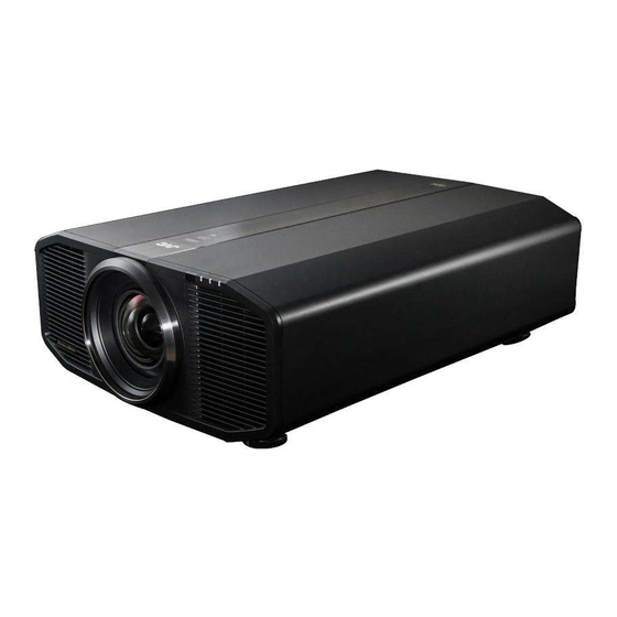
DLA-RS4500
.
http://manual3.jvckenwood.com/projector/mobile/global/
The Mobile User Guide can be viewed on mobile internet devices including
smartphones and tablets.
.
For Customer use :
Enter below the serial No. which is
located on the side of the cabinet.
Retain this information for future
reference.
Model No.
DLA-RS4500 K
Serial No.
.
Not suitable for household room illumination.
MODE 1
MODE 2
MODE 3
SETTING MEMORY
ANAMO.
HDR
PICTURE
COLOR
GAMMA
MODE
PROFILE
SETTINGS
C.M.D.
Mobile User Guide
Pour utilisation par le client :
Entrerci-dessous le N°de série qui
est situé sous le boîtier. Garder
cetteinformation comme référence
pour le futur.
N° de modèle
DLA-RS4500 K
N° de série
INSTRUCTIONS
Instrucción para el cliente :
Introduzca a continuación el nº de
serie que aparece en la parte
inferior lateral de la caja. Conserve
esta información como referencia
para uso ulterior.
Modelo Nº
DLA-RS4500 K
Nº de serie
B5A-2008-09
Advertisement
Chapters
Table of Contents

Related Manuals for JVC DLA-RS4500


Summary of Contents for JVC DLA-RS4500
- Page 1 Conserve reference. pour le futur. esta información como referencia para uso ulterior. Model No. DLA-RS4500 K N° de modèle DLA-RS4500 K Modelo Nº DLA-RS4500 K Serial No. N° de série Nº de serie Not suitable for household room illumination.
-
Page 2: Safety Precautions
FCC INFORMATION (U.S.A. only) WARNING: TO PREVENT FIRE OR SHOCK HAZARDS, DO CAUTION: NOT EXPOSE THIS APPLIANCE TO RAIN OR Changes or modification not approved by JVC could MOISTURE. void the user’s authority to operate the equipment. NOTE: WARNING: This equipment has been tested and found to comply THIS APPARATUS MUST BE EARTHED. -
Page 3: Important Safeguards
IMPORTANT SAFEGUARDS 150 mm (6 in) and above Electrical energy can perform many useful functions. This unit has been engineered and manufactured to assure your personal safety. But IMPROPER USE 300 mm 300 mm CAN RESULT IN POTENTIAL ELECTRICAL (12 in) and (12 in) and SHOCK OR FIRE HAZARD. - Page 4 If installation is performed by an authorized JVC service center. unqualified person, it may cause personal injury or When fixing the unit to the ceiling, Please note that we do electrical shock.
- Page 5 THIS APPARATUS MUST BE EARTHED. Fuse Dear Customer, This apparatus is in conformance with the valid European directives and standards regarding electromagnetic compatibility and electrical safety. European representative of JVC KENWOOD Corporation is: JVCKENWOOD Deutschland GmbH Konrad-Adenauer-Allee 1-11 61118 Bad Vilbel Germany...
- Page 6 ENGLISH Information for Users on Disposal of Old Equipment and Batteries [European Union only] These symbols indicate that equipment with these symbols should not be disposed of as general household waste. If you want to dispose of the product or battery, please consider the collection systems or facilities for appropriate recycling.
- Page 7 For the customers In the U.S.A. and Canada CAUTION Use of controls or adjustments or performance of procedures other than those LASER RADIATION RAYONNEMENT LASER specified herein may result in hazardous radiation exposure. AVOID DIRECT EYE EVITER L’EXPOSITION EXPOSURE DIRECTE DES YEUX CLASS 32 LASER PRODUCT PRODUIT LASER DE CLASSE 3R This Projector is classified as a CLASS 3R LASER PRODUCT.
- Page 8 For the customers In other countries CLASS 1 LASER PRODUCT LASER CAUTION LABEL WARNING Do not look into the lens while in use. CAUTION Use of controls or adjustments or performance of procedures other than those specified herein may result in hazardous radiation exposure.
-
Page 9: Table Of Contents
Contents Getting Started Fine-tuning the Image Quality ....... 36 Adjusting the Output Value of the Projected Image Safety Precautions ..........2 (Gamma) ............36 Accessories/Optional Accessories ......10 Fine-tuning to the Preferred Gamma Setting ..38 Check the Accessories ........10 Reducing the After-image of Fast-moving Images Optional Accessories ......... -
Page 10: Accessories/Optional Accessories
Accessories/Optional Accessories Check the Accessories Lens Cover ................1 piece Remote control ............... 1 piece AAA-size batteries (for operational check) ......2 pieces BADGE ................... 1 piece Power cord (for USA) (about. 2 m) (about. 78.7 in) ....1 piece Quick User Guide, safety precautions, warranty card, and other printed material are also included. -
Page 11: Controls And Features
Controls and Features Main Unit - Front A Lens C Indicator This is a projection lens. Do not look through the lens Refer to “Indicator Display on the Main Unit”P. 76. while an image is projected. D Exhaust vent B Remote Sensor (front) Warm air is discharged to cool down the internal Please aim the remote control at this area when using temperature. -
Page 12: Main Unit - Rear
Main Unit - Rear F Input terminals I Power input terminal In addition to the video input terminal, there are also Connect the supplied power cord to this terminal. other connection terminals for devices such as J Air Inlets controllers and optional equipment. Please see “Main Unit - Input Terminals”P. -
Page 13: Main Unit - Input Terminals
Main Unit - Input Terminals Enlarged View of Rear Face A [3D SYNCHRO] terminal E [HDMI 1] input terminal By connecting a 3D SYNCHRO EMITTER (sold F [HDMI 2] input terminal separately) to this terminal, you can view 3D movies. For connecting to devices that support HDMI output. -
Page 14: Remote Control
Remote Control A B [STAND BY] P [COLOR PROFILE] Displays the color profile selection Turns off the power. (P. 25) menu. (P. 32) B C [ON] Pressing the button each time Turns on the power. (P. 24) switches the configurable color profile in sequence. -
Page 15: Loading Batteries Into The Remote Control
Loading Batteries into the Remote Control If the remote control has to be brought closer to the Loading the batteries unit to operate, it means that the batteries are wearing out. Replace the batteries with new ones (AAA). Insert the batteries according to the t s marks. Be sure to insert the s end first. -
Page 16: Menu
Menu Select the icon at the top of the menu to display its corresponding setting item as shown below. A Picture Adjust B Input Signal C Installation D Display Setup E Function F Information... -
Page 17: Installing The Projector
Installing the Projector Precautions during Installation Please read the following carefully before installing this Maintain clearance from the wall, etc. unit. As the unit discharges a large amount of heat, install it with adequate clearance from the surroundings as shown When carrying this unit below. -
Page 18: Precautions During Mounting
Precautions during Mounting Securing with screws Securing (mounting) the projector 4 Locations Remove the four feet at the bottom, and fasten using the screws (M5 screws, 15 to 25 mm). * Using screws other than those designated may cause the unit to break down. When this unit is to be mounted to a fixed position for use, install it horizontally. - Page 19 Take the necessary actions to prevent the main unit from falling off such as during an earthquake. Regardless of the warranty period, JVC is not liable for any product damage caused by mounting the unit with non-JVC ceiling fittings or to an environment that is not suited for ceiling mount.
-
Page 20: Adjusting The Position
Adjusting the Position Adjusting the elevation angle of the projector Adjusting the position of the image The height and inclination of the unit (0 to 5 mm (0 to 0.2 By using the lens shift feature of this unit, you can shift in)) can be adjusted by turning the feet. -
Page 21: Connecting The Projector
Connecting the Projector Do not turn on the power until connection is complete. The connection procedures differ according to the device used. For details, please refer to the instruction manual of the device to be connected. This projector is used for projecting images. To output the audio of connected devices, please connect a separate audio output device, such as an amplifier or speaker. -
Page 22: Connecting To The Lan Terminal
Connecting via HDMI-DVI conversion cable Desktop PC, etc. This Unit To [HDMI 1] or [HDMI 2] input terminal DVI Output Terminal HDMI-DVI Conversion Cable (Sold Separately) If noise occurs, move the desktop PC away from this unit. If the video is not displayed, try to reduce the length of the cable or lower the resolution of the video transmitting equipment. -
Page 23: Connecting To The Trigger Terminal
Connecting to the TRIGGER Terminal Screen This Unit To [TRIGGER] Terminal Trigger Input Terminal (Ø3.5) Trigger Cable (Sold Separately) Do not use it to supply power to other devices. Connecting to the audio terminal of another device may cause the device to malfunction or break down. Using beyond the rated value will cause the unit to malfunction. -
Page 24: Viewing Videos
Viewing Videos MEMO Make sure to remove the lens cover. Connect the power cord, and ensure that the “STANDBY/ON” indicator lights up in red. During standby in the “ECO Mode”, the “STANDBY/ON” indicator does not light up even when the power cord is correctly connected. In this case, cancel the standby mode by pressing any button on the remote control unit, or use the A button on the projector unit when you are turning on the power. -
Page 25: Turn Off The Power
Turn off the power Remote control: press the B [STAND BY] button Projector unit: press the A button While the “Are you sure you want to turn off?” message is displayed, press the button again. The light of the LD block goes off, and the “STANDBY/ON” indicator switches from a green light to a red blinking light. -
Page 26: Adjusting The Projector Screen
Adjusting the Projector Screen Adjusting the Lens According to the Projection Position Press the [LENS CONTROL] button, and use the [JKH I] keys to adjust Focus, Zoom (screen size), and Shift (screen position) MODE 1 MODE 2 MODE 3 SETTING MEMORY Focus ANAMO. -
Page 27: Setting Screen Correction
Setting Screen Correction Set Screen Adjust MEMO By selecting the optimal correction mode according to the characteristics of the screen in You can utilize the optional optical sensor and use, corrections can be performed to reproduce dedicated projector calibration software to make finer natural images with balanced colors. -
Page 28: Adjusting The Screen Size (Aspect)
Adjusting the Screen Size (Aspect) The screen size of the projected image can be adjusted optimally according to the original screen size (aspect) that has been input. Press the [MENU] button to display the menu Select “Input Signal” " “Aspect” in the menu, then select the setting and press [OK] Input Level Auto Color Space... -
Page 29: Viewing 3D Movies
Viewing 3D Movies By using the 3D GLASSES (PK-AG1, PK-AG2, or PK-AG3) and 3D SYNCHRO EMITTER (PK-EM1 or PK-EM2), both sold separately, you can enjoy 3D video images. For 3D GLASSES and 3D SYNCHRO EMITTER that are compatible with this unit, please refer to “Optional Accessories”P. -
Page 30: Viewing 3D Movies
Viewing 3D Movies Connect this unit to a 3D-compatible Format Description HDMI device, and turn on the power Auto Automatically determines and to play back the 3D video image sets the format upon receiving 3D For details on how to play back 3D video images, signal. -
Page 31: Selecting An Image Quality According To The Video Type
Selecting an Image Quality According to the Video Type Setting the Picture Mode You can adjust the image quality according to the type of video image you are viewing. Press the [PICTURE MODE] button, and use the [JK] keys to select and set the desired “Picture Mode” You can also perform the setting by pressing the [MENU] button to display the menu followed by selecting “Picture Adjust”... -
Page 32: Setting The Color Profile
Color space that is suitable for CG animation works. Ideal for animated works with bright colors. Cinema Original JVC cinema-specific color gamut that achieves a balance between increased brightness and color vividness. Color space suitable for HDR content. Film 1 Color space that is close to the characteristics of Eastman Kodak Company movie films. - Page 33 List of selectable “Color Profile” according to “Picture Mode” Picture Mode Color Profile Natural BT.709 BT.2020 Anime. Cinema BT.709 BT.2020 Cinema BT.2020 BT.709 Film Film 1 Film 2 User 1 to User 6 BT.709 BT.2020 Anime. Cinema Custom1 to Custom6...
-
Page 34: Adjusting To The Preferred Color (Color Management)
Adjusting to the Preferred Color (Color Management) Based on the setting of the selected “Color Profile”, you can adjust each of the following colors according to your preference: Red, Yellow, Green, Cyan, Blue, and Magenta. Press the [ADVANCED MENU] button to display the “Color Profile” menu Set “Color Management”... -
Page 35: Adjusting Movies For Increased Detail And Sharpness (Multiple Pixel Control)
Adjusting Movies for Increased Detail and Sharpness (Multiple Pixel Control) The new image-processing algorithm developed by JVC Make adjustments according to your helps to create a natural impression that is sharper at preference based on the setting of the areas in focus, and softer at areas that are not in focus, enabling you to enjoy highly detail 4K images with a selected “Picture Mode”... -
Page 36: Fine-Tuning The Image Quality
Fine-tuning the Image Quality Adjusting the Output Value of the Projected Image (Gamma) You can adjust the output value of the projected image with respect to the video signal input. Example of gamma adjustment The overall image appear brighter with respect to the original image, making the dark areas more visible. Input Value The photos are for illustrative purposes only. - Page 37 “Gamma” Gamma Description When “Color Profile” is Film 1 Image is close to the characteristics of Eastman Kodak Company set to “Film 1” movie films. Film 2 Places more emphasis on the gradation compared to the “Film 1” setting. When “Color Profile” is Film 1 Places more emphasis on the contrast compared to the “Film 2”...
-
Page 38: Fine-Tuning To The Preferred Gamma Setting
Fine-tuning to the Preferred Gamma Setting You can perform fine adjustments based on the selected gamma adjustment setting. Press the [GAMMA SETTINGS] button to display the gamma menu You can also perform setting from “Picture Adjust”"“Gamma” in the menu. Adjust to the preferred setting Select the color to be adjusted from “Color Selection”... -
Page 39: Gamma Adjustment
When “Correction Value” is set to “Import” By selecting “Import” for “Correction Value”, the gamma data created externally can be selected as the base setting value for adjustment. The factory setting for “Import” is “2.2”. You can use the calibration software to customize the gamma data adjustment, and import the created gamma data. Please check with your authorized dealer for details. -
Page 40: Reducing The After-Image Of Fast-Moving Images (Blur Reduction)
Reducing the After-image of Fast-moving Images (Blur Reduction) Low Latency For changing the low latency setting. You are recommended to set to “On” for content requiring split-second timing with the operation screen of PC signals or games. Press the [MENU] button to display the menu and select “Picture Adjust”"“Blur Reduction”"“Low Latency”... - Page 41 Motion Enhance Optimal image quality with reduced image blurring is made possible by enhancing the responsiveness of the liquid crystal device. If the image outline is unnatural, set this item to “Off”. Press the [MENU] button to display the menu and select “Picture Adjust”"“Blur Reduction”"“Motion Enhance”...
-
Page 42: Adjustments And Settings In The Menu
Adjustments and Settings in the Menu Pressing the [MENU] button displays the menu. Press the [JKH I] keys to select an item, followed by pressing the [OK] button to confirm the selection. List of Menu Items Picture Adjust Picture Mode ..............................P. 31 9 Dynamic CTRL ............................ - Page 43 Installation Installation Mode ............................. P. 50 Lens Control ..............................P. 26 9 Focus ................................. P. 26 9 Zoom ................................P. 26 9 Shift ................................P. 26 9 Image Pattern ............................. P. 51 9 Lock ................................P. 51 9 Lens Center ..............................P. 51 Pixel Adjust ..............................
-
Page 44: Picture Adjust
Picture Adjust Picture Mode You can adjust the image quality according to the type of video image you are viewing. Æ “Setting the Picture Mode” (P. 31) You can configure the following setting items by pressing the [MENU] button to display the menu, followed by selecting “Picture Adjust”... -
Page 45: Color Profile
Color Profile By setting the “Color Profile” (color space information) according to the “Picture Mode”, you can fine-tune the image quality according to the movie you are viewing. Æ “Setting the Color Profile” (P. 32) Color Management Each of the colors is adjustable according to the user’s preference. Æ... - Page 46 List of selectable “Color Temp.” according to “Picture Mode” Picture Mode Color Temp. Film Xenon 1 Xenon 2 Custom 1 to Custom 2 Cinema 5500K 6500K 7500K 9300K Xenon 1 Xenon 2 High Bright Custom 1 to Custom 2 Natural 5500K 6500K User 1 to User 6...
-
Page 47: Gamma
Correction Value For setting the base color temperature for the adjustment of “Gain Red” / “Gain Green” / “Gain Blue” / “Offset Red” / “Offset Green” / “Offset Blue” when one of the “Custom 1” to “Custom 3” setting is selected in “Color Temp.”. Gain Red / Gain Green / Gain Blue Adjusts each color in the bright parts of the video image. -
Page 48: Mpc Level
MPC Level You can enjoy natural, expressive 4K images with a stronger sense of depth. Æ “Adjusting Movies for Increased Detail and Sharpness (Multiple Pixel Control)” (P. 35) Graphic Mode For selecting whether the content you are viewing is of high sharpness such as graphics. It is recommended to set to “4K”... -
Page 49: Input Signal
Input Signal Input Level For setting the dynamic range (gradation) of the video input. If the image is not displayed properly even after selecting “Auto”, select an appropriate setting. If the dynamic range is not appropriate, the bright areas become overexposed, and the dark areas become underexposed. -
Page 50: Installation
Installation Installation Mode Collectively manages the setting values of “Lens Control”, “Pixel Adjust”, “Mask”, “Anamorphic” and “Screen Adjust”. Mode Select For selecting the group to save and retrieve the setting values. Setting values: Mode 1 to Mode 10 * The name of the setting value can be changed using “Name Edit”. Name Edit For editing the name of Installation Mode. -
Page 51: Lens Control
Lens Control Focus / Zoom / Shift For adjusting the lens according to the projection position Æ “Adjusting the Lens According to the Projection Position” (P. 26) Image Pattern For setting whether to display the lens adjustment pattern. Setting Description Displays the lens adjustment pattern. -
Page 52: Pixel Adjust
Pixel Adjust For correcting the phase shifting between each RGB color by adjusting the pixel. Adjust For setting the adjustment feature to On or Off. Adjust Area Setting Description Whole Adjusts the entire image. Zone Enables fine adjustment of each area by dividing the screen evenly into 10 vertical and horizontal zones. - Page 53 Whole Adjust (Pixel) Operation Procedure For making general adjustments to slight color fringing in the horizontal/vertical directions of the video image. A Set “Adjust Area” to “Whole” B Select “Adjust Color” and “Adjust Pattern Color” C Select “Adjust (Pixel)”, and press the [OK] button The Adjustment mode is activated, and the selected adjustment pattern and Adjustment (Pixel) window are displayed.
- Page 54 Whole Adjust (Fine) Operation Procedure For making general adjustments on the misalignment of the entire screen using “Adjust (Pixel)”, followed by making fine adjustments. A Set “Adjust Area” to “Whole” B Select “Adjust Color” and “Adjust Pattern Color” C Select Adjust (Fine), and press the [OK] button The Adjustment mode is activated, and the selected adjustment pattern and Fine window are displayed.
- Page 55 Zone Adjust Operation Procedure For fine-tuning misalignments on a part of the screen after adjusting the overall screen misalignment using “Adjust (Pixel)” and “Adjust (Fine)”. The screen can be divided vertically and horizontally into 10 sections for partial adjustments to be made. A Set “Adjust Area”...
-
Page 56: Mask
Mask For hiding the peripheral area of the image with a mask (black strip). Setting Description Not masked. Hides the ranges specified in “Top”, “Bottom”, “Left” and “Right” by masking (with black strips). Mask: black strip around the periphery “Top” / “Bottom” / “Left” / “Right” For specifying the ranges to hide by masking (with black strips). -
Page 57: Display Setup
Pincushion Corrects the geometric distortion that occurs when projecting on a curved screen. Setting range: 0 to 16 * This function cannot be used if “Keystone” is set. High Altitude Mode For setting the high altitude mode to “On” or “Off”. Set to “On”... -
Page 58: Function
Function Trigger For setting whether to supply a 12 V output to devices such as an external screen equipped with a trigger function. Setting Description No output. Power Outputs control signals (12 V) from the trigger terminal when the power is turned Anamo Outputs control signals when the “Anamorphic”... -
Page 59: Network
Network For specifying the settings for external control from a PC or smartphone. Setting Description DHCP Client Obtains the IP address automatically from the DHCP server inside the connected network. For configuring the network settings manually. IP Address For configuring the IP address. Subnet Mask For configuring the subnet mask. -
Page 60: Information
Factory Reset For restoring the settings of this unit to factory default. However, the following settings will not reset. Gamma data saved in “Gamma” " “Correction Value” " “Import”. Color profile data saved in “Color Profile” " “Custom1 to Custom6”. Software Update For performing software update. -
Page 61: Maintaining The Cabinet And Remote Control
Maintaining the Cabinet and Remote Control Gently wipe off dirt on the cabinet with a soft cloth. If it is extremely dirty, wet a cloth in water, wring dry and use it to wipe off the dirt, followed by wiping again with a dry cloth. -
Page 62: Troubleshooting
Troubleshooting Before sending the unit to your authorized dealer for repair, please check the following points. The following symptoms are not malfunctions. You do not need to worry about the following symptoms if there is no abnormality on the screen. A part of the top or front surface of the unit is hot. - Page 63 Video image does not appear Check Action Refer to Is the correct external input selected? Select the correct external input terminal. P. 24 Is the power of the AV device or PC Turn on the power of the AV device or PC and play the P.
- Page 64 Video image looks unnatural Colors are unnatural Check Action Refer to Is the color space of the input signal The color may turn out unnatural when the input signal is P. 49 correctly set? different from that in the projector setting. Set the “Color Space”...
- Page 65 Striped patterns appear on the screen Check Action Refer to Does the fabric of the screen have a Interference fringes may sometimes occur between the — regular pattern? fabric pattern and the pixels. Please consult the authorized dealer. Video images are missing Check Action Refer to...
-
Page 66: When The Following Messages Appear
When the Following Messages Appear... Message Description Action No device is connected to the input Input the video signals. terminal. No Input The input terminal is connected but there is no signal. A video signal that cannot be used with Input video signals that can be used. -
Page 67: External Control
External Control It is possible to control this unit by connecting it to a PC using an RS-232C cross cable (D-sub 9-pin). The projector can be controlled by connecting it to a PC through the computer network with a LAN cable for control commands to be sent to the projector. -
Page 68: Command Format
Command Format The command between this unit and the computer consists of “Header”, “Unit ID”, “Command”, “Data” and “End”. Header (1 byte), Unit ID (2 bytes), Command (2 bytes), Data (n bytes), End (1 byte) Header This binary code indicates the start of communication. Binary Code Type Description... -
Page 69: Remote Control Code
Remote Control Code Binary code is sent during communication. The following applies to the case when the remote control code is “A”. In the case of “B”, add “36” to the beginning of the code. Remote Control Button Name Binary Code Remote Control Button Name Binary Code STAND BY... -
Page 70: Communications Example
Communications Example This section shows the communication examples of RS-232C. Operating command Type Command Description Connection check PC " This unit: 21 89 01 00 00 0A Connection check This unit " PC: 06 89 01 00 00 0A Power (On) PC "... -
Page 71: Specifications
Specifications Product Name D-ILA Projector Model Name DLA-RS4500 Display Panel/Size D-ILA device *1, 2 0.69” 4K D-ILA (4096 x 2160 pixels) x 3 Projection Lens 2.0 x power zoom lens (1.4:1 to 2.8:1), motorized zoom and focus Light Source BLU-Escent (Laser Diode) Screen Size Approx. - Page 72 This unit has obtained the “THX 4K DISPLAY Certification” determined by THX Ltd. In addition to 2K content, you can also enjoy faithful reproduction of images in a quality as intended by the filmmaker during playback of 4K content. The THX 4K DISPLAY certification is “an indication of high definition and high resolution”, which is granted to products that have cleared more than 400 image quality tests.
-
Page 73: Screen Size And Projection Distance
Screen Size and Projection Distance Projection Distance (m) Screen Size 17:9 Screen 16:9 Screen 2.35:1 Screen 4:3 Screen Diagonal (Model) Wide-end Tele-end Wide-end Tele-end Wide-end Tele-end Wide-end Tele-end 1.66 3.43 1.75 3.61 1.86 3.82 2.16 4.44 1.96 4.02 2.06 4.23 2.18 4.47 2.54... - Page 74 Projection Distance (ft) Screen Size 17:9 Screen 16:9 Screen 2.35:1 Screen 4:3 Screen Diagonal (Model) Wide-end Tele-end Wide-end Tele-end Wide-end Tele-end Wide-end Tele-end 5.46 11.26 5.75 11.85 6.09 12.52 7.10 14.56 6.42 13.18 6.76 13.87 7.15 14.65 8.33 17.03 7.37 15.10 7.76 15.88...
- Page 75 Types of Possible Input Signals Video Digital Video Signal 480p 576p 720p 50/60 Hz 1080i 50/60 Hz 1080p 24/25/30/50/60 Hz 2K (2048×1080) 24/25/30/50/60 Hz 4K (3840x2160) 24/25/30/50*/60* Hz 4K (4096x2160) 24/25/30/50*/60* Hz 3D Signal Frame Packing 720p 50/60 Hz 1080p 24 Hz Side-by-side 720p 50/60 Hz 1080p 50/60/24 Hz...
- Page 76 Indicator Display on the Main Unit Meaning of the lighting figures The indicator lights up. The indicator appears blinking. Operation mode display Displays using the different colors and solid/blinking light of the indicator on the projector unit. “STANDBY/ON” lights up (red) “STANDBY/ON”...
- Page 77 Warning display You can tell the details of a warning from the (repeated) displays of the “WARNING” and “LIGHT” indicators. The “STANDBY/ON” indicator will light up or appear blinking according to the operation mode of the projector unit. (Please refer to ““Operation mode display”P. 76”.) The Warning mode is activated once the message is displayed.
- Page 78 Dimensions (Unit: mm (in)) Top Surface Bottom Surface 337 (13.3) 41 (1.6) 37 (1.5) 500 (19.7) Rear Surface Front 157 (6.2) 175 (6.9) (5.2) (8.1) (5.2)
-
Page 79: Index
Index Input Signal ............ 60, 75 A Accessories ............10 Input terminals ............. 13 Adjusting Distortion of the Projection Screen ..26 Installation Method ..........17 Adjustment and Setting by the Menu ....42 Installing the 3D Syncro Emitter ......29 Adjustment of the Image Quality ...... - Page 80 U User Name Edit ........... 44 Symbol 3D Crosstalk Cancel ..........30 3D Format ............30 V Viewing 3D Movies ..........29 3D Glasses ............ 10, 29 Viewing Videos ............ 24 3D Setting ............49 3D Synchro Emitter ........10, 29 W When the following messages appear...
- Page 84 © 2016 JVCKENWOOD Corporation 1116KSY-SW-IT...