Advertisement
Table of Contents
E528 Smart Digital Thermostat Product Guide
Table of Contents
Rev 8.0 12/16/2016
Table of Contents .............................................. Page 1
Overview and General Concept ......................... Page 2
Application ......................................................... Page 2
Wireless Communication ................................... Page 4
Installation Requirements .................................. Page 4
Mounting ............................................................ Page 5
Input/Output ....................................................... Page 6
E528.4G New Installation .................................. Page 8
Wiring ................................................................ Page 10
Load Specifications ........................................... Page 13
FCC Information ................................................ Page 13
Technical Specifications .................................... Page 14
Document Revision History ............................... Page 15
E528 Product Guide
1
Advertisement
Table of Contents

Related Manuals for Honeywell e528


Summary of Contents for Honeywell e528
-
Page 1: Table Of Contents
E528 Product Guide E528 Smart Digital Thermostat Product Guide Table of Contents Table of Contents ..........Page 1 Overview and General Concept ......Page 2 Application ............Page 2 Wireless Communication ........Page 4 Installation Requirements ........Page 4 Mounting ............Page 5 Input/Output ............ -
Page 2: Overview And General Concept
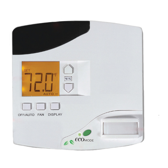
(RF) transceiver and Passive Infrared (PIR) motion detector. The e528 interfaces with all common HVAC unit voltage configurations (24 volt to 277 volt). The e528 can be installed in a wired or wireless INNCOM guestroom control system, which makes installation feasible and affordable in either new construction or retrofit installations. - Page 3 TCT (an Ethernet gateway device). RF networking is possible with radio equipped models. The e528 features a guest-friendly graphic interface with intuitive controls (Figure 2). A user guide for the e528, written primarily for installers and facility management personnel, is available (see References below). Figure 2. E528 Graphic Interface...
-
Page 4: Wireless Communication
11-26 11-26 Installation Requirements Location: The e528 must be located on a partitioning interior wall, approximately 1.5 m (5 ft) above the floor, in a site of average temperature. It is important to ensure that the thermostat is located away... -
Page 5: Mounting
E528 Product Guide Mounting The e528 is usually mounted on a standard double-gang (4 x 4) junction box. If mounted on a single-gang box, the left side (display side) of the e528 overlaps the wall area to the left of the junction box. A low-voltage mounting plate, mud ring, or low-voltage caddy may be used for mounting 24 volt applications. -
Page 6: Input/Output
* “3G,” and “4G” are internal INNCOM product designations used for convenience to differentiate individual hardware configurations. No difference in device capability or effectiveness is implied. Due to end-of-life for certain 3G components, the e528.4G is now the standard INNCOM install, but 3G installations are still supported. - Page 7 RS485 Networks: (refer to Figure 5) E528.3G cannot act as the media gateway for in-room traffic towards the RS485 network. The most common way to connect the e528.3G is to connect a PC-485.S5 (P/N: 01-9905) on the S5bus. E528.4G to 2G RS485 Networked Application: with or without door switch...
-
Page 8: E528.4G New Installation
Stand alone application with/without door switch input Using the harness (P/N 62-1467), make the appropriate wire • connections, then plug the harness into the low voltage comm/device connection of the e528.4G RS485 Networked Application with/without door switch input (See Figure 7) •... - Page 9 E528 Product Guide The e528.4G can be used to retrofit an application where a legacy e528 was used. Follow the procedure below: 4G to 2G Standalone application: with/without door switch input (no backhaul network) • Using the adapter (P/N 203-013) connect the harness from...
-
Page 10: Wiring
The steps below provide an overview of the wiring process. Refer to the as- built wiring diagrams provided for exact details. 1. If applicable, use wire nuts to connect the 6-pin low-voltage harness wires to the applicable low-voltage communication (if e528 is part of a wired Rev 8.0 12/16/2016... - Page 11 3. Plug the pre-wired 10-pin connector into the female receptacle at the back of the e528. 4. Hook the tabs at the top rear of the e528 housing into the matching depressions at the top of the mounting plate and rotate the bottom of the housing toward the wall until it snaps into place on the mounting plate.
- Page 12 MUST door/window switch, PASS OVER the external PIR wiring physical separator to the low voltage side To E528 low voltage comm header To the E528 10-pin Molex Socket Figure 11. Electrical Box Connections 24VAC Rev 8.0 12/16/2016...
-
Page 13: Load Specifications
E528 Product Guide Load Specifications The following load specification table (Table 6) describes the submitted load characteristics for testing and UL certification of UL 873. The device complies with the requirements of CAN/CSA C22.2 No. 24-93. Table 6. Load Specifications... -
Page 14: Technical Specifications
Technical Specifications Table 7. Technical Specifications Power Requirements 24 VAC at 50/60 Hz, 24 VDC nominal, 2.4 VA (e528-3xx/7xx and e528-4xx) 100 to 277 VAC at 50/60 Hz, 2.4 VA (e528-8xx) Relay Contact Rating See Table 4. -
Page 15: Document Revision History
The material in this document is for information purposes only. The content and the product it describes are subject to change without notice. Honeywell makes no representations or warranties with respect to this document. In no event shall Honeywell be liable for technical or editorial omissions or mistakes in this document, nor shall it be liable for any damages, direct or incidental, arising out of or related to the use of this document.