Table of Contents
Advertisement
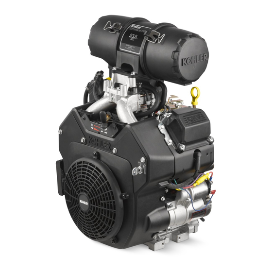
CH682, CH732, CH742, CH752
Service Manual
IMPORTANT:
Read all safety precautions and instructions carefully before operating equipment. Refer to operating
instruction of equipment that this engine powers.
Ensure engine is stopped and level before performing any maintenance or service.
2
Safety
3
Maintenance
5
Specifi cations
13
Tools and Aids
16
Troubleshooting
20
Air Cleaner/Intake
21
Fuel System
27
Governor System
29
Lubrication System
31
Electrical System
38
Starter System
42
Disassembly/Inspection and Service
56
Reassembly
24 690 34 Rev. D
KohlerEngines.com
1
Advertisement
Table of Contents
Troubleshooting

Related Manuals for Kohler command pro CH742


Summary of Contents for Kohler command pro CH742
- Page 1 CH682, CH732, CH742, CH752 Service Manual IMPORTANT: Read all safety precautions and instructions carefully before operating equipment. Refer to operating instruction of equipment that this engine powers. Ensure engine is stopped and level before performing any maintenance or service. Safety Maintenance Specifi...
-
Page 2: Safety Precautions
Safety SAFETY PRECAUTIONS WARNING: A hazard that could result in death, serious injury, or substantial property damage. CAUTION: A hazard that could result in minor personal injury or property damage. NOTE: is used to notify people of important installation, operation, or maintenance information. CAUTION WARNING WARNING... -
Page 3: Maintenance Instructions
Have a Kohler authorized dealer perform this service. REPAIRS/SERVICE PARTS Kohler genuine service parts can be purchased from Kohler authorized dealers. To fi nd a local Kohler authorized dealer visit KohlerEngines.com or call 1-800-544-2444 (U.S. and Canada). 24 690 34 Rev. D... -
Page 4: Oil Recommendations
Maintenance OIL RECOMMENDATIONS STORAGE We recommend use of Kohler oils for best performance. If engine will be out of service for 2 months or more Other high-quality detergent oils (including synthetic) follow procedure below. of API (American Petroleum Institute) service class SJ 1. -
Page 5: Specifications
Specifi cations Engine Dimensions Dimensions in millimeters. 526.84 [20.742] PRIMARY AIR FILTER Inch equivalents shown in [ ]. ELEMENT REMOVAL 414.52 [16.320] SAFETY AIR FILTER ELEMENT REMOVAL 450.90 VALVE FUEL PUMP [17.752] COVER 298.74 334.78 [11.761] 135.00 92.98 [13.180] [5.315] 272.52 130.00 [5.118] [3.661]... -
Page 6: Engine Identification Numbers
Lubricate threads with engine oil prior to assembly. Any and all horsepower (hp) references by Kohler are Certifi ed Power Ratings and per SAE J1940 & J1995 hp standards. Details on Certifi ed Power Ratings can be found at KohlerEngines.com. - Page 7 Specifi cations TORQUE SPECIFICATIONS CH682 CH732 CH742 CH752 Crankcase Breather Cover Fastener 11.3 N·m (100 in. lb.) into new holes 7.3 N·m (65 in. lb.) into used holes Oil Drain Plug 13.6 N·m (10 ft. lb.) Cylinder Head Fastener (torque in 2 increments) fi...
-
Page 8: Clearance Specifications
Specifi cations TORQUE SPECIFICATIONS CH682 CH732 CH742 CH752 Oil Sentry ™ Pressure Switch 4.5 N·m (40 in. lb.) Solenoid (Starter) Mounting Hardware 4.0-6.0 N·m (35-53 in. lb.) Nut, Positive (+) Brush Lead 8.0-11.0 N·m (71-97 in. lb.) Speed Control Bracket Fastener 10.7 N·m (95 in. - Page 9 Specifi cations CLEARANCE SPECIFICATIONS CH682 CH732 CH742 CH752 Crankshaft End Play (free) 0.070/0.590 mm (0.0028/0.0230 in.) End Play (w/thrust bearing components) 0.070/1.190 mm (0.0028/0.0468 in.) Bore (in crankcase) 40.965/41.003 mm (1.6128/1.6143 in.) Max. Wear Limit 41.016 mm (1.6148 in.) Crankshaft to Sleeve Bearing (crankcase) Running Clearance-New 0.03/0.09 mm (0.0012/0.0035 in.) Bore (in closure plate)
- Page 10 Specifi cations CLEARANCE SPECIFICATIONS CH682 CH732 CH742 CH752 Governor Governor Cross Shaft-to-Crankcase Running Clearancet 0.025/0.126 mm (0.0009/0.0049 in.) Cross Shaft O.D. 7.949/8.000 mm (0.3129/0.3149 in.) Max. Wear Limit 7.936 mm (0.3124 in.) Governor Gear Shaft-to-Governor Gear 0.015/0.140 mm (0.0006/0.0055 in.) Running Clearance Gear Shaft O.D.
- Page 11 Specifi cations CLEARANCE SPECIFICATIONS CH682 CH732 CH742 CH752 Valves and Valve Lifters Hydraulic Valve Lifter to Crankcase Running Clearance 0.0241/0.0501 mm (0.0009/0.0020 in.) Intake Valve Stem-to-Valve Guide Running Clearance 0.038/0.076 mm (0.0015/0.0030 in.) Exhaust Valve Stem-to-Valve Guide Running Clearance 0.050/0.088 mm (0.0020/0.0035 in.) Intake Valve Guide I.D.
-
Page 12: General Torque Values
Specifi cations GENERAL TORQUE VALUES English Fastener Torque Recommendations for Standard Applications Bolts, Screws, Nuts and Fasteners Assembled Into Cast Iron or Steel Grade 2 or 5 Fasteners Into Aluminum Size Grade 2 Grade 5 Grade 8 Tightening Torque: N·m (in. lb.) ± 20% 8-32 2.3 (20) 2.8 (25) -
Page 13: Tools And Aids
Shrader Valve Adapter Hose DTI-037 Wire Probe Set (2 pieces regular wire with clip; 1 piece fused wire) DTI-031 Hose Removal Tool, Dual Size/End (also sold as individual Kohler tool) DTI-033 Flywheel Puller SE Tools KLR-82408 For properly removing fl ywheel from engine. - Page 14 For reaming worn valve guides to accept replacement oversize valves. Can be used in low-speed drill press or with handle below for hand reaming. Reamer Handle Design Technology Inc. For hand reaming using Kohler 25 455 12-S reamer. DTI-K830 AIDS Description Source/Part No.
- Page 15 Tools and Aids FLYWHEEL HOLDING TOOL ROCKER ARM/CRANKSHAFT TOOL A fl ywheel holding tool can be made out of an old junk A spanner wrench to lift rocker arms or turn crankshaft fl ywheel ring gear and used in place of a strap wrench. may be made out of an old junk connecting rod.
-
Page 16: Troubleshooting Guide
Troubleshooting TROUBLESHOOTING GUIDE When troubles occur, be sure to check simple causes which, at fi rst, may seem too obvious to be considered. For example, a starting problem could be caused by an empty fuel tank. Some general common causes of engine troubles are listed below and vary by engine specifi cation. Use these to locate causing factors. - Page 17 Troubleshooting EXTERNAL ENGINE INSPECTION Engine Loses Power NOTE: It is good practice to drain oil at a location away ● Dirty air cleaner element. from workbench. Be sure to allow ample time for ● Engine overheated. complete drainage. ● Excessive engine load. ●...
-
Page 18: Crankcase Vacuum Test
Troubleshooting CRANKCASE VACUUM TEST WARNING WARNING Carbon Monoxide can cause severe nausea, Rotating Parts can cause severe injury. fainting or death. Stay away while engine is in operation. Avoid inhaling exhaust fumes. Engine exhaust gases contain poisonous carbon Keep hands, feet, hair, and clothing away from all monoxide. -
Page 19: Compression Test
Troubleshooting COMPRESSION TEST For Command Twins: A compression test is best performed on a warm engine. Clean any dirt or debris away from base of spark plug(s) before removing them. Be sure choke is off, and throttle is wide open during test. Compression should be at least 160 psi and should not vary more than 15% between cylinders. -
Page 20: Air Cleaner/Intake
Air Cleaner/Intake AIR CLEANER 1. Unhook retaining clips and remove end cap(s). These systems are CARB/EPA certifi ed and components 2. Check and clean inlet screen (if equipped). should not be altered or modifi ed in any way. 3. Pull air cleaner element out of housing and replace. Air Cleaner Components Check condition of inner element;... -
Page 21: Fuel Pump
2. Remove screws and take off pump. Low permeation fuel line must be installed on carbureted 3. Connect pulse line to new fuel pump and make sure Kohler Co. engines to maintain EPA and CARB opposite end is properly connected to fi tting on regulatory compliance. - Page 22 Fuel System CARBURETOR Gasoline is extremely fl ammable and its vapors can WARNING explode if ignited. Store gasoline only in approved Explosive Fuel can cause fi res and severe containers, in well ventilated, unoccupied buildings, away burns. from sparks or fl ames. Spilled fuel could ignite if it comes in contact with hot parts or sparks from ignition.
-
Page 23: Troubleshooting Checklist
Fuel System Engines in this series are equipped with a two-barrel side-draft carburetor with fi xed main jets on a matching intake manifold. Carburetor features a self-relieving choke, serviceable slow jets, main jets, accelerator pump, and a fuel shutdown solenoid. 4. - Page 24 Fuel System Fuel Shut-Off Solenoid Carburetor Adjustments Carburetors are equipped with a fuel shut-off solenoid. NOTE: Carburetor adjustments should be made only Solenoid is attached to fuel bowl. Solenoid has a spring- after engine has warmed up. loaded pin that retracts when 12 volts is applied to lead, Carburetor is designed to deliver correct fuel-to-air allowing fuel flow to main jet.
- Page 25 Fuel System 1. Perform removal procedures for appropriate air Carburetor Servicing cleaner and carburetor outlined in Disassembly. 2. Clean exterior surfaces of dirt or foreign material WARNING before disassembling carburetor. Disconnect accelerator pump vacuum hose from bottom of bowl. Remove screws and carefully separate fuel bowl Accidental Starts can cause severe injury or from carburetor.
- Page 26 Engines may require a high altitude carburetor kit to ensure correct engine operation at altitudes above 1219 meters (4000 ft.). To obtain high altitude kit information or to fi nd a Kohler authorized dealer visit KohlerEngines.com or call1-800-544-2444 (U.S. and Canada).
-
Page 27: Governor System
Governor System GOVERNOR Engine is equipped with a centrifugal fl yweight mechanical governor. It is designed to hold engine speed constant under changing load conditions. Governor gear/fl yweight mechanism is mounted inside crankcase on closure plate, and is driven off gear on camshaft. Governor Components H Inside Engine Throttle Lever... - Page 28 Governor System Sensitivity Adjustment Governor sensitivity is adjusted by repositioning governor spring in holes of governor lever. If speed surging occurs with a change in engine load, governor is set too sensitive. If a big drop in speed occurs when normal load is applied, governor should be set for greater sensitivity and adjust as follows: 1.
-
Page 29: Lubrication System
Lubrication System This engine uses a full pressure lubrication system which CHANGE OIL AND FILTER delivers oil under pressure to crankshaft, camshaft, Change oil while engine is warm. connecting rod bearing surfaces, and hydraulic valve 1. Clean area around oil fi ll cap/dipstick, drain plug/oil lifters. -
Page 30: Installation
Lubrication System OIL SENTRY (if equipped) ™ This switch is designed to prevent engine from starting in a low oil or no oil condition. Oil Sentry may not shut ™ down a running engine before damage occurs. In some applications this switch may activate a warning signal. Read your equipment manuals for more information. -
Page 31: Electrical System
Electrical System SPARK PLUGS Inspection Inspect each spark plug as it is removed from cylinder CAUTION head. Deposits on tip are an indication of general Electrical Shock can cause injury. condition of piston rings, valves, and carburetor. Do not touch wires while engine is running. Normal and fouled plugs are shown in following photos: Normal Spark Plug Component and Details... - Page 32 Electrical System Carbon Fouled ELECTRONIC IGNITION SYSTEMS Ignition System Components Soft, sooty, black deposits indicate incomplete combustion caused by a restricted air cleaner, over rich Kill Switch/ carburetion, weak ignition, or poor compression. Off Position of Air Gap Key Switch Overheated Flywheel Magnet...
- Page 33 Electrical System Wiring Diagram-15/20/25 Amp Regulated Battery Charging System 24 690 34 Rev. D KohlerEngines.com...
- Page 34 Electrical System Ignition Systems These systems use a capacitive discharge (CD) coil. With CDI fi xed timing, ignition timing and spark remains constant regardless of engine speed. Timing of spark is controlled by location of fl ywheel magnet group as referenced to engine TDC.
-
Page 35: Battery Charging System
Electrical System Test for Spark NOTE: If 2 testers are available, testing can be performed simultaneously for both cylinders. However, if only 1 tester is available, 2 individual tests must be performed. Side not being tested must have spark plug lead connected or grounded. - Page 36 Electrical System To test 20/25 amp rectifi er-regulators: 1. 20 amp: Connect single lead adapter in between B+ (center) terminal of rectifi er-regulator being tested and squared single end of tandem adapter lead. 25 amp: Connect squared single end of tandem lead adapter to B+ (center/red) lead of rectifi er-regulator being tested.
- Page 37 Electrical System 15/20/25 Amp Battery Charging Systems NOTE: Always zero ohmmeter on each scale before testing to ensure accurate readings. Voltage tests should be made with engine running at 3600 RPM with no load. Battery must be good and fully charged. When problems occur in keeping battery charged or battery charges at high rate, charging system or battery might be causing problems.
-
Page 38: Starter System
Starter System NOTE: Do not crank engine continuously for more than 10 seconds. Allow a 60 second cool down period between starting attempts. Failure to follow these guidelines can burn out starter motor. NOTE: If engine develops suffi cient speed to disengage starter but does not keep running (a false start), engine rotation must be allowed to come to a complete stop before attempting to restart engine. - Page 39 Starter System SOLENOID SHIFT ELECTRIC STARTERS Starter Disassembly Solenoid Shift Starter Components NOTE: Do not reuse old retainer. NOTE: Do not soak armature or use solvent when cleaning. Wipe clean using a soft cloth, or use compressed air. 1. Remove hex nut and disconnect positive (+) brush lead/bracket from solenoid terminal.
-
Page 40: Brush Replacement
4 brushes and springs are serviced as a set. Use a new assembly, with supplied protective tube, against Kohler brush and spring kit if replacement is necessary. end of commutator/armature. Mounting screw 1. Perform steps 1-5 in Starter Disassembly. -
Page 41: Solenoid Tests
Starter System b. Position brushes back in their slots so they are fl ush with I.D. of brush holder assembly. Insert brush installation tool (with extension), or use tube described above from a prior brush installation, through brush holder assembly, so holes in metal mounting clips are up/out. c. -
Page 42: Disassembly/Inspection And Service
Disassembly/Inspection and Service WARNING Before working on engine or equipment, disable engine as Accidental Starts can cause severe injury or follows: 1) Disconnect spark plug lead(s). 2) Disconnect death. negative (–) battery cable from battery. Disconnect and ground spark plug lead(s) before servicing. - Page 43 Disassembly/Inspection and Service Filter Electric Starter Lifting Bracket Fixed Guard Blower Housing Wire Clip Oil Filter Nipple Valve Cover Fuel Oil Cooler Pulse Fuel Pump Air Cleaner Pump Clean all parts thoroughly as engine is disassembled. Remove Fuel Pump Only clean parts can be accurately inspected and gauged for wear or damage.
- Page 44 Disassembly/Inspection and Service 2. If required use nuts locked together and remove Remove Throttle and Choke Controls carburetor mounting studs on starter side of intake manifold and one stud on oil fi lter side. Control Bracket Components Pivot carburetor to clear breather cover fi tting and pressure switch (if equipped).
- Page 45 Disassembly/Inspection and Service Remove Intake Manifold Remove Valve Covers 1. Remove screws securing intake manifold to cylinder 1. Remove screws securing each valve cover. Note heads. Note which screws hold wiring clamps. position of any attached brackets or lifting straps. 2.
-
Page 46: Exhaust Valve
Disassembly/Inspection and Service 3. Once valve spring is compressed, remove following Disassemble Cylinder Heads items. NOTE: These engines use valve stem seals on intake ● Valve spring keepers. valves. Use a new seal whenever valve is ● Valve spring retainers. removed or if seal is deteriorated in any way. - Page 47 Check base surface of hydraulic lifters for wear or Replace valves found to be in bad condition. damage. If lifters need to be replaced, apply a liberal coating of Kohler lubricant to base of each new lifter Valve Guides before it is installed.
- Page 48 Inspect ring gear for cracks or damage. Kohler does not 3. If there is a plastic debris screen attached to fan, provide ring gear as a serviceable part. Replace fl ywheel remove screws securing screen.
- Page 49 Disassembly/Inspection and Service Crankcase Components Gerotor Gears Oil Seal Closure Plate (Style A) Dipstick Tube (Style A) Oil Pick-Up Tube Oil Pump Assembly Governor Gear Shaft Governor Gear (Style A) (Style A) Camshaft Piston Pin Piston Ring Set Piston Pin Retainer Connecting Rod End Piston Connecting Rod...
- Page 50 Disassembly/Inspection and Service Governor Gear Assembly Oil Pump Assembly (Style A) Oil Pump (Style A) Torque Sequence Governor Shaft Component and Details Oil pump is mounted inside closure plate. If service is required, refer to Disassembly, Inspection, and Reassembly. Disassembly Gear Shaft 1.
- Page 51 Disassembly/Inspection and Service Remove Oil Pump (Style B) Remove Connecting Rods with Pistons and Rings Oil pump is mounted inside closure plate. If service NOTE: If a carbon ridge is present at top of either is required, refer to Disassembly, Inspection, and cylinder bore, use a ridge reamer tool to remove Reassembly.
- Page 52 Disassembly/Inspection and Service NOTE: Rings must be installed correctly. Ring 3. Remove old rings and clean up grooves. Never installation instructions are usually included with reuse old rings. new ring sets. Follow instructions carefully. Use 4. Before installing new rings on piston, place top two a piston ring expander to install rings.
-
Page 53: Connecting Rods
Disassembly/Inspection and Service Carefully pull crankshaft from crankcase. Note thrust Connecting Rods washers and shims if used. Offset, stepped-cap connecting rods are used in all Inspect gear teeth of crankshaft. If teeth are badly worn, these engines. chipped, or some are missing, replacement of crankshaft Inspection and Service will be necessary. - Page 54 Disassembly/Inspection and Service Remove Governor Cross Shaft Crankcase 1. Remove hitch pin and plain washer, or retainer and Inspection and Service nylon washer from governor cross shaft. Check all gasket surfaces to make sure they are free of gasket fragments. Gasket surfaces must also be free of 2.
- Page 55 Measuring Piston-to-Bore Clearance Piston Detail 23°-33° Crosshatch NOTE: Kohler pistons are custom-machined to exacting tolerances. When oversizing a cylinder, it should be machined exactly 0.25 mm (0.010 in.) or 0.50 mm (0.020 in.) over new diameter (refer to Specifi...
- Page 56 Reassembly Crankcase Components Gerotor Gears (Style Oil Seal Closure Plate (Style A) Dipstick Tube Oil Pick-Up Tube Oil Pump Assembly Governor Gear Shaft Governor Gear (Style A) (Style A) Camshaft Piston Pin Piston Ring Set Piston Pin Retainer Connecting Rod End Piston Connecting Rod Crankshaft...
-
Page 57: Install Crankshaft
Reassembly 4. Make sure FLY stamping on piston is facing towards Install Governor Cross Shaft fl ywheel side of engine. Use a hammer with a rubber 1. Lubricate governor cross shaft bearing surfaces in grip and gently tap piston into cylinder as shown. Be crankcase with engine oil. - Page 58 Reassembly Thrust Bearing, Washer and Shim Install Closure Plate Oil Seal Oil Seal Depth Thrust Shim Thrust Washer Seal Depth Oil Seal Needle Thrust 8.0 mm (0.314 in.) Bearing Race Bearing Closure Plate 1. Check to make sure there are no nicks or burrs in crankshaft bore of closure plate.
- Page 59 Reassembly RTV sealant is used as a gasket between closure plate Install Closure Plate Assembly and crankcase. Always use fresh sealant. Using outdated sealant can result in leakage. Sealant Pattern and Torque Sequence 1. Be sure sealing surfaces have been cleaned and prepared.
-
Page 60: Install Flywheel
Reassembly Install Flywheel Install Plastic Debris Screen CAUTION CAUTION Damaging Crankshaft and Flywheel can Failure to utilize or reassemble debris screen cause personal injury. as designed could result in debris screen failure and serious personal injury. If engine has a plastic debris screen, place plastic Using improper procedures can lead to broken fragments. - Page 61 Reassembly Cylinder Head Components Valve Stud Gasket Spark Plug Valve Stem Seal Hydraulic Lifter Retainer Valve Spring Valve Spring Retainer Push Rod Valve Keeper Rocker Arm Rocker Arm Pivot Valve Cover O-ring Valve Cover Assemble Cylinder Heads Install Hydraulic Lifters Prior to installation, lubricate all components with engine NOTE: Hydraulic lifters should always be installed in oil, paying particular attention to lip of valve stem seal,...
- Page 62 Reassembly 4. Install cylinder head. Match numbers on cylinder Install Cylinder Heads heads and crankcase. Make sure head is fl at on Cylinder Head Torque Sequence gasket and dowel pins. 5. Lightly lubricate exposed (upper) threads of studs with engine oil. Install a new fl at washer and nut onto each mounting stud.
-
Page 63: Install Ignition Modules
Reassembly Install Ignition Modules Install Intake Manifold 1. Rotate fl ywheel to position magnet away from Torque Sequence ignition module bosses. 2. CDI modules are installed with spark plug lead wire from module always away from cylinder. On cylinder 1, single kill tab should be towards you. On cylinder 2, single kill tab should be away from you (in). - Page 64 Reassembly External Engine Components Intake Manifold Intake Manifold Carburetor Gasket Carburetor Gasket Air Cleaner Gasket Outer Baffl e Breather Tube Oil Sentry ™ Breather Cover Breather Gasket Inner Baffl e Breather Reed Filter Electric Starter Lifting Bracket Fixed Guard Blower Housing Wire Clip Oil Filter Nipple...
- Page 65 Reassembly 4. If rectifi er-regulator was not removed, attach ground Install Breather Cover and Inner Baffl es wire or metal grounding bracket for rectifi er- Breather Cover Torque Sequence regulator, using silver colored screw and washer, to lower blower housing hole. 5.
-
Page 66: Install Carburetor
Reassembly 3. connect leads to solenoid. Control Bracket Components Install Fuel Pump WARNING Explosive Fuel can cause fi res and severe burns. Do not fi ll fuel tank while engine is hot or running. Gasoline is extremely fl ammable and its vapors can explode if ignited. - Page 67 Reassembly Governor Lever Hole Position Install Oil Sentry (if equipped) ™ 1. Apply pipe sealant with Tefl on (Loctite 592™ ® ® ® or equivalent) to threads of Oil Sentry switch and ™ install it into breather cover. Torque to 4.5 N·m (40 in.
- Page 68 Reassembly Install Air Cleaner Assembly Install Oil Filter and Fill Crankcase with Oil Torque Sequence NOTE: Make sure both oil drain plugs are installed and torqued to specifi cations to prevent oil leakage. 1. Install oil drain plug(s). Torque plug(s) to 13.6 N·m 3, 7 1, 5 (10 ft.
- Page 69 24 690 34 Rev. D KohlerEngines.com...
- Page 70 KohlerEngines.com 24 690 34 Rev. D...
- Page 71 24 690 34 Rev. D KohlerEngines.com...
- Page 72 1P24 690 34 85612 22193 © 2015 by Kohler Co. All rights reserved. KohlerEngines.com 24 690 34 Rev. D...