Kenwood KAC-M1804 Service Manual
Hide thumbs
Also See for KAC-M1804:
- Instruction manual (17 pages) ,
- Instruction manual (2 pages) ,
- Instruction manual (2 pages)
Advertisement
Table of Contents
SERVICE MANUAL
3 S ERVICE MANUAL
2015
WA122<Rev.002>
DC cord
(E30-8358-05)
COPYRIGHT © 2015 JVC KENWOOD Corporation
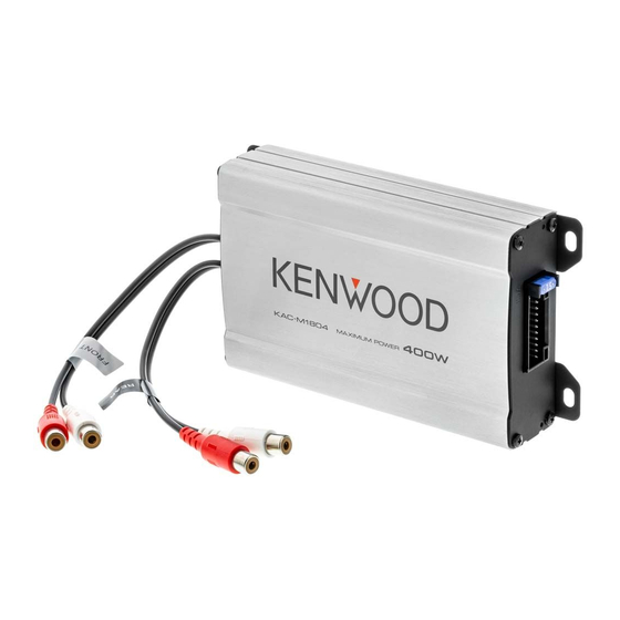
POWER AMPLIFIER
KAC-M1804
Screw set
Cord with pinplug
(N99-1840-05)
(E3A-00xx-00) x2
COPYRIGHT © 2015 JVC KENWOOD Corporation
KAC-M1804 (North America) : K0
KAC-M1804 (Europe)
Wire band
(J61-0629-05) x2
This product uses Lead Free solder.
This product complies with the RoHS directive for the European market.
: E1
Wire band
(J61-0620-05) x2
PbF
No.WA122<Rev.002>
2015/3
Advertisement
Table of Contents

Related Manuals for Kenwood KAC-M1804


Summary of Contents for Kenwood KAC-M1804
- Page 1 SERVICE MANUAL POWER AMPLIFIER WA122<Rev.002> 2015 3 S ERVICE MANUAL KAC-M1804 KAC-M1804 (North America) : K0 KAC-M1804 (Europe) : E1 DC cord Screw set Cord with pinplug Wire band Wire band (J61-0629-05) x2 (J61-0620-05) x2 (E30-8358-05) (N99-1840-05) (E3A-00xx-00) x2 This product uses Lead Free solder.
-
Page 2: Installation
SPECIFICATION Audio section Max power output 400 W 4 Ω Speaker impedance Frequency response (+0, -1 dB) 20 Hz - 20 kHz Signal to noise ratio 90 dB Input impedance 10 kΩ General Operating voltage 14.4 V (11 - 16 V allowable) Current consumption 15 A Dimensions (W ×... - Page 3 SECTION 1 PRECAUTION Safety Precautions (1) This design of this product contains special hardware and Critical parts for safety many circuits and components specially for safety purpos- In regard with component parts appearing on the silk-screen es. For continued protection, no changes should be made printed side (parts side) of the PWB diagrams, the parts that are to the original design unless authorized in writing by the printed over with black such as the resistor (...
- Page 4 SECTION 2 SPECIFIC SERVICE INSTRUCTIONS How to repair a fuse pattern 2.1.1 Purpose of fuse pattern In order to prevent serious damage on the circuit, fuse pattern is prepared on the GND line of RCA Terminal. This damage may take due to improper part replacement with a external equipment via RCA line. 2.1.2 Repair Procedure (1) Check the shorted circuit at the meltdown point.
- Page 5 Ref. No. Application / Function Operation / Condition / Compatibility D201 Diode for -26dB ATT circuit and Auto P- Con control D233 Diode for -26dB ATT circuit error prevention Prevents -26dB ATT circuit from turning on when P-CON is Hi D215 Temperature protection circuit diode 5.1V Zener diode for the temperature protection circuit...
- Page 6 SECTION 3 DISASSEMBLY Removing the Audio unit (See Fig.1 to 4) (3) Remove the 4 screw C, and remove the Panel(L). (See Fig.3) (1) Remove the 4 screws A, and remove the Bottom plate. (See Fig.1) PANEL(L) Fig.3 (4) Disconnector the wire from connector CN1. (See Fig.4) (5) Remove the 4 screws D, and remove the Audio unit.
- Page 7 JVC KENWOOD Corporation CE Segment 2967-3, Ishikawa-machi, Hachioji-shi, Tokyo, 192-8525, Japan (No.WA122<Rev.002>) Printed in Japan...
-
Page 8: Schematic Diagrams
SCHEMATIC DIAGRAMS POWER AMPLIFIER KAC-M1804 (No.WA122<Rev.002>)1/6... - Page 9 PRECAUTIONS ON SCHEMATIC DIAGRAMS Due to the improvement in performance, some part numbers shown in the circuit diagrams may not agree with those indicated in the Parts List. The parts numbers, values and rated voltage etc. in the Schematic Diagrams are for reference only.
-
Page 10: Block Diagram
BLOCK DIAGRAM Power Amp SP IN : -26dB RCA IN or RCA IN : 0dB Speaker +23.3dB -3.3dB Speaker Level IN fc:55kHz +9.9dB TotalGain IC10 A_L+ IC12 RCA IN:+29.9dB A_L- Digital AMP SP IN:+3.9dB Driver&FET IC A_L+ Filter [IR4302] Input A_R+ A_L- A_R-... - Page 11 AUDIO UNIT (X09-9220-10) +11.5V +11.5V ISA1602AM1(F) TP110 TP106 Q232 -11.5V -11.5V RCA_IN(Lo) / SP_IN(Hi) DA2J101 RF101L2S SP IN/RCA IN TP59 (-26dB/0dB) 0.01u 0.01u 0.01u 0.01u 4.7k 1/8W 0.01u 0.01u Q233 R313 _0.5% BA4564RFV 150p 4.7k IC10 (1/4) IC12 (1/4) 1000p ALch BA4564RFV (1/4)
- Page 12 AUDIO UNIT X09-9220-10 (J76-0911-02) C244 C207 C103 C104 R165 R166 R205 R103 R104 C167 C168 Q230 Q231 IC11 IC10 C101 C102 Q220 Q219 R313 R314 C271 R309 C273 C165 C166 R310 D201 R101 R102 C275 R260 R163 R164 TP71 TP69 R258 R259 R261...
- Page 13 AUDIO UNIT X09-9220-10 (J76-0911-02) How to repair a fuse pattern. Refer to "2.1 How to repair a fuse pattern". TP12 TP95 TP124 TP96 TP97 TP100 TP98 TP32 TP93 TP64 TP94 TP65 TP31 TP80 TP101 TP15 TP99 TP67 TP59 TP104 TP103 TP60 TP63 TP43...
-
Page 14: Parts List
PARTS LIST POWER AMPLIFIER KAC-M1804 (No.WA122<Rev.002>)1/10... - Page 15 PRECAUTIONS ON SCHEMATIC DIAGRAMS Due to the improvement in performance, some part numbers shown in the circuit diagrams may not agree with those indicated in the Parts List. The parts numbers, values and rated voltage etc. in the Schematic Diagrams are for reference only.
-
Page 16: Exploded View
EXPLODED VIEW Block No.200 Parts with the exploded numbers larger than 700 are not supplied. No.WA122 created date:2015-03-23 (No.WA122<Rev.002>)3/10... - Page 17 MODEL MARK MODEL MARK KAC-M1804 KAC-M1804 Safe Symbol No. Parts No. Parts Name Description Local EXPLODED VIEW <200> E30-8358-05 DC CORD F52-0024-05 FUSE N09-6952-05 TAPTITE SCREW N09-6959-05 TAPTITE SCREW A64-5574-12 PANEL A64-5575-12 PANEL E30-8371-05 CORD W.PINPLUG J61-0620-05 WIRE BAND J61-0629-05...
- Page 18 MODEL MARK MODEL MARK KAC-M1804 KAC-M1804 Safe Symbol No. Parts No. Parts Name Description Local AUDIO UNIT (X09-9220-10) <X09> BA4564RFV ANALOGUE IC NJM4565E-ZB ANALOGUE IC NJM4565E-ZB ANALOGUE IC IR4302MTRPBF MOS IC IR4302MTRPBF MOS IC BA4564RFV ANALOGUE IC BA10358F ANALOGUE IC...
- Page 19 MODEL MARK MODEL MARK KAC-M1804 KAC-M1804 Safe Symbol No. Parts No. Parts Name Description Local D229 DA2J101 DIODE D232 DZ2J068M Z DIODE D233 DA2J101 DIODE CE32CL1C220M E CAPACITOR 22uF 16V M CE32CL1C220M E CAPACITOR 22uF 16V M CE32CL1C220M E CAPACITOR...
- Page 20 MODEL MARK MODEL MARK KAC-M1804 KAC-M1804 Safe Symbol No. Parts No. Parts Name Description Local C118 CK73GBB1H103K C CAPACITOR 0.01uF 50V K C119 CE32CL1C220M E CAPACITOR 22uF 16V M C120 CE32CL1C220M E CAPACITOR 22uF 16V M C121 CC73GCH1H331J C CAPACITOR...
- Page 21 MODEL MARK MODEL MARK KAC-M1804 KAC-M1804 Safe Symbol No. Parts No. Parts Name Description Local C244 CE32CL1C470M E CAPACITOR 47uF 16V M C245 CE32CL0J470M E CAPACITOR 47uF 6.3V M C246 CE32CL0J470M E CAPACITOR 47uF 6.3V M C247 CK73GBB1H103K C CAPACITOR 0.01uF 50V K...
- Page 22 MODEL MARK MODEL MARK KAC-M1804 KAC-M1804 Safe Symbol No. Parts No. Parts Name Description Local R102 RK73GB2A472J MG RESISTOR 4.7kΩ 1/10W J R103 RK73GB2A472J MG RESISTOR 4.7kΩ 1/10W J R104 RK73GB2A472J MG RESISTOR 4.7kΩ 1/10W J R106 RK73GB2A223J MG RESISTOR 22kΩ...
- Page 23 MODEL MARK MODEL MARK KAC-M1804 KAC-M1804 Safe Symbol No. Parts No. Parts Name Description Local R234 RK73PB2H100J MG RESISTOR 10Ω 1/2W J R235 RK73GB2A133J MG RESISTOR 13kΩ 1/10W J R236 RK73GB2A331J MG RESISTOR 330Ω 1/10W J R237 RK73GB2A682J MG RESISTOR 6.8kΩ...