Table of Contents
Advertisement
Quick Links
Advertisement
Table of Contents

Summary of Contents for LOUD Technologies SR1530
- Page 1 SR1530 REPAIR MANUAL SR1530 REPAIR MANUAL...
-
Page 2: Tools Needed
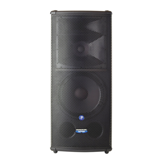
These instructions are intended to help restore any ailing SR1530 Active Loudspeaker back to factory working conditions. They show how to remove and replace the drivers and the amplifi er assembly. Please contact Mackie Technical Support (1-800-898-3211) to receive a Service Request Number and Order Number for parts needed for this restoration. - Page 3 Led PCB replacement: Four screws need to be removed from each side of the grill (eight screws total) using the phillips head screwdriver. Carefully begin to remove the grill. Do not fully remove the grill as the cable is still fi rmly attached to the led PCB assembly.
- Page 4 Place the new led PCB assembly (part #0007334) where the old one was. Follow the same steps as above, but backwards 6 to 1. Power up the SR1530 and the led should light up. Congratulations, you just replaced an led PCB assembly...now go...
-
Page 5: Woofer Replacement
Woofer replacement: Follow steps 1-4 of the led PCB replacement instructions, as the grill will need to be removed in order to access the woofer. Keep the eight screws and fl at washers in a safe place. Carefully begin to remove the woofer. A fl... - Page 6 The picture on the right shows what the SR1530 looks like with the grill and woofer removed . Place the new woofer (part #0008873-01) where the old one was.
- Page 7 High Frequency Driver replacement: Follow steps 1-4 of the led PCB replacement instructions, as the grill will need to be removed in order to access the high frequency driver. Keep the fourteen screws and fl at washers in a safe place. High High Frequency...
- Page 8 High Frequency Driver replacement continued: Pull out Pull out Pull out Pull out The positive (solid green) and negative (green and black) cables are still attached to the mid frequency driver terminals. Do not force cable removal The positive (solid blue) and negative or connection, although needle-nose (blue and black) cables are still pliers may aid in loosening the crimped...
- Page 9 High Frequency Driver replacement continued: This is what it looks like with the grill and Two nuts and four washers may be horn assembly removed. Continued removed from the driver using the 8mm on the right are further instructions and combination wrench.
- Page 10 (part #0010022) where the old one was by following the same steps as above, but backwards 11 to 1. Power up the SR1530 and the new driver should now be pumping out those highs again. Fantastic, you just replaced a high frequency driver!
-
Page 11: Diaphragm Replacement
Follow the same steps as above, but backwards 5 to 1. Power up the SR1530 and the new diaphragm should now be pumping out those highs again. Sweet, you just replaced a... - Page 12 Amplifi er Assembly replacement: Keep the sixteen screws in a safe place. 1 1 2 2 3 3 4 4 5 5 6 6 top down view (close up) The amplifi er assembly is now ready to be separated from the cabinet. Do not completely take the amplifi...
- Page 13 Power up the SR1530 and relish in the fact that you just replaced an amplifi er assembly. Hats off to you for a job well done! Important: The faulty amplifi...
- Page 14 This page left blank intentionally...
