Marantz sr7010 User Manual
Integrated network av receiver
Hide thumbs
Also See for sr7010:
- Owner's manual (377 pages) ,
- Service manual (237 pages) ,
- Quick start manual (13 pages)
Table of Contents
Advertisement
Quick Links
- 1 Front Panel
- 2 Rear Panel (1 of 3)
- 3 Rear Panel (3 of 3)
- 4 Remote Control (1 of 4)
- 5 Specifications - Audio Section
- 6 Specifications - Bluetooth Section, General Section
- 7 Sr7010 - Protection History Display Mode (1 of 3)
- 8 Sr7010 - Protection History Display Mode (2 of 3)
- Download this manual
See also:
Owner's Manual
Model Information
Index
Front Panel
Rear Panel
Remote Control
Warranty
Reset Procedure
Accessories
Protection History
Display Mode
Upgrades/Updates
Product Specifications
I/R Codes
NOTE:
This edition is missing the link to the IR codes................................................................................ 11/21/2016
MODEL:
Model Information
INTEGRATED NETWORK AV RECEIVER
SR7010
MI112116E3-1
Advertisement
Table of Contents

Related Manuals for Marantz sr7010


Summary of Contents for Marantz sr7010
- Page 1 MODEL: SR7010 Model Information Index Model Information Front Panel INTEGRATED NETWORK AV RECEIVER Rear Panel Remote Control Warranty Reset Procedure Accessories Protection History Display Mode Upgrades/Updates Product Specifications I/R Codes NOTE: This edition is missing the link to the IR codes…………………………………………………………………….. 11/21/2016...
-
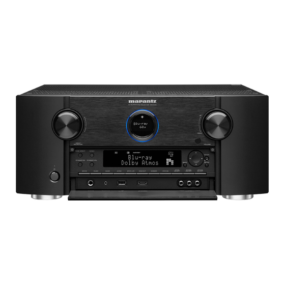
Page 2: Front Panel
Front Panel Power operation button ( INPUT SELECTOR knob This selects the input source. Used to turn the power of the MAIN ZONE Main display (room where this unit is located) on/off This displays various pieces of information. (standby). Remote control sensor ... -
Page 3: With The Door Open (1 Of 3)
With The Door Open (1 of 3) A-DSX DYNAMIC EQ button Sub display This switches the Dynamic EQ settings. This displays various pieces of information. PURE DIRECT button/indicator BACK button This switches the sound mode between Direct, Pure Direct and This returns to the previous screen. -
Page 4: With The Door Open (2 Of 3)
With The Door Open (2 of 3) Speaker A/B switching button (SPKR A/B) MOVIE button This sets the front speakers to use. This switches the sound mode to “Movie”. HDMI OUT button MUSIC button This sets the HDMI monitor output. This switches the sound mode to “Music”. -
Page 5: With The Door Open (3 Of 3)
With The Door Open (3 of 3) ZONE SELECT button SETUP MIC jack These switch the zone (MAIN ZONE, ZONE2, ZONE3) that is operated This is used to connect the supplied Sound calibration through the remote control unit. microphone. ZONE2 ON/OFF button USB port (T) This turns the power of ZONE2 on/off. -
Page 6: Main Display (1 Of 2)
Main Display (1 of 2) Main display The input source name, sound mode, setting values and other information are displayed here. Standard display Tuner display These light up according to the reception conditions when the input source is set to “HD Radio”. A Light illumination When the power to this device is switched on, the surrounding area is lit blue. -
Page 7: Main Display (2 Of 2)
Main Display (2 of 2) Sleep timer indicator ZONE2/ZONE3 power on display This lights when the sleep mode is selected. This lights up when ZONE2 (separate room) power is turned on. This lights up when ZONE3 (separate room) power is turn HOME MAIN DISPLAY (2 of 2) -
Page 8: Sub Display
Sub Display 7 8 9 Input signal indicators MUTE indicator The respective indicator will light corresponding to the input signal. This blinks while the sound is muted. link, Decoder indicators Volume indicator These light when Dolby or DTS signals are input or when the Dolby or DTS ... -
Page 9: Rear Panel (1 Of 3)
Rear Panel (1 of 3) Bluetooth/wireless LAN antenna connectors DC OUT jacks Used to connect the included external antennas for Used to connect devices equipped with the trigger function. Bluetooth/wireless connectivity when connecting to a Digital audio connectors (DIGITAL AUDIO) network via wireless LAN, or when connecting to a handheld Used to connect devices equipped with digital audio connectors. -
Page 10: Rear Panel (2 Of 3)
Rear Panel (2 of 3) FLASHER IN jack HDMI connectors Used when using a control BOX or other such control devices Used to connect devices equipped with HDMI connectors. to control “Connection 1 : TV equipped with an HDMI connector and this unit. -
Page 11: Rear Panel (3 Of 3)
Rear Panel (3 of 3) FM/AM antenna terminals (ANTENNA) PRE OUT connectors Used to connect FM antennas and AM loop antennas. Used to connect a subwoofer with built-in amplifier or an Analog audio connectors (AUDIO) external power amplifier. Used to connect devices equipped with analog audio ... -
Page 12: Remote Control (1 Of 4)
Remote Control (1 of 4) Display 1. LEARN indicator This is lit when setting the learning function for the remote control unit. 2. Information display This displays “AVR” when operating this unit. This displays the input source name when operating an external device. ... -
Page 13: Remote Control (2 Of 4)
Remote Control (2 of 4) Device operation buttons (DEVICE “On/Off” / DEVICE MENU) These turn the power of external devices on/off and call up menus. Preset codes need to be registered in order to use these buttons. Input source select buttons These select the input source. -
Page 14: Remote Control (3 Of 4)
Remote Control (3 of 4) HOME button This takes you to the Home screen (Top screen) when the input source is Online Music. System buttons These perform playback related operations. Tuning up / Tuning down buttons (TUNE +, –) These select either FM broadcast or AM broadcast. SMART SELECT buttons (1 - 4) These call up settings registered to each button, such as input source, volume level and sound mode settings. -
Page 15: Remote Control (4 Of 4)
Remote Control (4 of 4) TV operation buttons (TV X / TV MENU / TV INPUT) These turn the TV power on/off, switch the TV input and call up menus. Preset codes need to be registered in order to use these buttons. Light button This turns on the backlight for approx. -
Page 16: Marantz Usa Limited Warranty (1 Of 2)
Length of Non-Transferable Warranty This warranty on your Marantz product which is distributed and warranted by Marantz America Inc. remains in effect for the following periods from the date of the original consumer purchase from an AUTHORIZED DENON ELECTRONICS (USA), LLC DEALER. - Page 17 How you can get service If your unit needs service, contact Marantz customer service by calling 201-762-6666. We will advise you of the name and location of one or more authorized Marantz service stations from which service can be obtained. Please do not return your unit to the factory without prior authorization.
- Page 18 Reset “A-DSX” button “GAME” button Power/Standby button Reset procedure: With the power off, press and hold the “A-DSX” button, “GAME” button, and “POWER” button simultaneously on the AVR for a few seconds until “INITIALIZED” appears on the AVR’s display Initialized Resetting the micro is a procedure used to "reboot"...
- Page 19 Accessories Sound Remote Control Sound Calibration (RC026SR) Calibration Microphone Microphone Stand (ACM1HB) 30701020600AM $59.99 32401000800AD $31.99 963549101000D $14.99 AM Loop FM Indoor Power Cord) Antenna Antenna 963116100070S $8.99 943116100170D $5.44 943611500750D $10.99 Safety CD ROM External Instructions Antennas For Owner’s Bluetooth/Wire Manual less...
- Page 20 FAQ’s ( 1 of 2) HOME ACCESSORIES FAQ’s 2...
- Page 21 FAQ’s (2 of 2) HOME FAQ’s 1 UPGRADE...
- Page 22 Dolby Atmos and DTS:X surround sound technologies dispense with channel-based coding in favor of object-based coding, giving the sound designer the ability to precisely place sounds anywhere in the 3-dimensional space. The SR7010, features the ability to connect a 5.1 surround sound speaker system and 4 additional overhead speakers (or 4 additional Dolby Atmos elevation speakers) for the ultimate home cinema experience.
- Page 23 Note: This will also check the time it will approximately take to complete the update. To check to see if an update or upgrade is available for your SR7010 and also to download the latest version of firmware, click on the following link: http://www.us.marantz.com/us/support/pages/productupdates.aspx...
-
Page 24: Specifications - Audio Section
Specifications – Audio Section Audio section 125 W + 125 W (8 Ω/ohms, 20 Hz – 20 kHz with 0.05 % T.H.D.) Front 165 W + 165 W (6 Ω/ohms, 1 kHz with 0.7 % T.H.D.) 125 W (8 Ω/ohms, 20 Hz – 20 kHz with 0.05 % T.H.D.) Center 165 W (6 Ω/ohms, 1 kHz with 0.7 % T.H.D.) Rated output... -
Page 25: Specifications - Video Section, Tuner Section, Wireless Lan Section
Specifications - Video section, Tuner Section, Wireless LAN Section Video section Input/output level and impedance 1 Vp-p, 75 Ω/ohms Standard video connectors Frequency response 5 Hz -10MHz, 0, - 3dB Y signal 1 Vp-p, 75 Ω/ohms Input/output level and impedance PB/CB signal 0.7 Vp-p, 75 Ω/ohms Color component video connector... -
Page 26: Specifications - Bluetooth Section, General Section
Specifications – Bluetooth Section, General Section Bluetooth section Communications system Bluetooth Version 2.1 + EDR (Enhanced Data Rate) Transmission power Maximum 2.5 mW (Class 2) Maximum communication range Approx. 32.8 ft/10 m in line of sight*2 Frequency band 2.4 GHz Modulation scheme FHSS (Frequency-Hopping Spread Spectrum) A2DP (Advanced Audio Distribution Profile) 1.2... -
Page 27: Specifications - Dimensions, Weight
Specifications – Dimensions, Weight Dimensions section (Unit : inch/mm) Weight: 30 lbs 7 oz (13.8 kg) HOME SPECIFICATIONS - SPECIFICATIONS - VIDEO – SPECIFICATIONS Protection History Display AUDIO TUNER – WIRELESS LAN BLUETOOTH - GENERAL Mode (Front Panel Buttons) -
Page 28: Sr7010 - Protection History Display Mode (1 Of 3)
SR7010 - Protection History Display Mode (1 of 3) Model Information Index Protection History Mode records and displays an event in which the THERMAL, CURRENT, ASO or DC protection was activated. POWER STATUS ZONE SELECT BACK ENTER Procedure to enter the “Protection History Display Mode”. -
Page 29: Sr7010 - Protection History Display Mode (2 Of 3)
SR7010 - Protection History Display Mode (2 of 3) Model Information Index 1. If no protections have occurred, “No Protect” is displayed 2. if last protection was ASO, “ASO” is displayed. Cause: A short circuit occurred between the speaker terminals, or speakers with an impedance outside the rating were connected. If the power is turned on during this abnormality, protection is activated after around 6 seconds and the power is turned off. -
Page 30: Sr7010 - Protection History Display Mode (3 Of 3)
SR7010 - Protection History Display Mode (3 of 3) Model Information Index Clearing the Protection History If the unit is in “Protection History Display Mode”, just press and hold the “ENTER” button for 3 seconds. Note: If you do not mind erasing your settings from this unit, you can also “Initialized/Micro Reset the unit to clear the Protection History from the unit’s... - Page 31 The End NOTE: This edition is missing the link to the IR Codes……………………………………………………………………...11/21/2016 HOME...