Table of Contents
Advertisement
Advertisement
Table of Contents

Summary of Contents for C-COM Satellite iNetVu 7710
- Page 1 ® 7710 Controller User Manual (Includes 7720) The iNetVu ® brand and logo are registered trademarks of C-COM Satellite Systems, Inc. © Copyright 2009 C-COM Satellite Systems, Inc. 1-877-iNetVu6 www.c-comsat.com March 10, 2015 Revision 4.00 Released with SW Version 7.7.3...
- Page 2 C-COM Satellite Systems Inc. This page is intentionally left blank. iNetVu™ 7710 Controller User Manual...
- Page 3 Reproduction, adaptation, or translation without prior written permission is prohibited, except as followed under the copyright laws. Both the iNetVu ® and C-COM names and logos are registered trademarks of C-COM Satellite Systems Inc. ® Intel Pentium is a registered trademark of Intel Corporation. Microsoft, Windows, Windows NT and MapPoint are registered trademarks of Microsoft Corporation.
- Page 4 C-COM Satellite Systems Inc. FCC and INDUSTRY CANADA INFORMATION TO THE USER: The FCC and Industry Canada have imposed the following conditions when operating, installing and deploying iNetVu ® Mobile Earth Stations and is mandatory for all installations made within the Continental United States and Canada as well as Hawaii, Alaska, Puerto Rico, the U.S.
- Page 5 C-COM Satellite Systems Inc. 7. Further, the installer and end user may be directly liable for any damages resulting from any change undertaken by either of them. Including but not limited to, any modification of any part of the hardware, software, specific operational frequencies, the authorized satellite, or the size or other characteristics of the earth station supplied to them by C- COM or C-COM’s authorized representatives.
-
Page 6: Table Of Contents
C-COM Satellite Systems Inc. Table of Contents Contents Introduction ........................9 Specifications ........................10 Minimum Recommended PC Requirements ..............10 Physical ..........................11 Typical Connection Configuration ..................12 5.1. Typical Network Interface Connection .................13 5.2. Typical USB Communication Interface ................14 5.3. Typical Connection – PC Free ..................15 Installation ........................16... - Page 7 C-COM Satellite Systems Inc. 7.10.9. PW ........................52 7.10.10. SG ........................52 7.10.11. IP ........................53 7.10.12. SR ........................53 7.11. TEST ..........................54 7.11.1. E&A&P ......................55 7.11.2. DPLY ........................56 7.11.3. DPLY_C ......................57 7.11.4. A_ACP ......................58 7.11.5. M_ACP ......................58 7.11.6. S_ACP ......................58 7.12. INFO ...........................58 7.12.1.
- Page 8 Proprietary Notice: This document contains information that is proprietary and confidential to C-COM Satellite Systems, Inc., and is intended for internal and or C-COM Satellite Systems Inc. authorized partners use only. No part of this document may be copied or reproduced in any way, without prior written permission of C-COM Satellite Systems, Inc.
-
Page 9: Introduction
C-COM Satellite Systems Inc. 1. Introduction ® The iNetVu 7710 Controller is a one-box, one-touch solution for satellite auto-acquisition. Designed to interface with a number of Satellite Modems, iNetVu ® VSATs, and DVB-S/DVB- S2ACM Receivers, the iNetVu ® 7710 Controller connects to iNetVu ®... -
Page 10: Specifications
C-COM Satellite Systems Inc. 2. Specifications Dimensions: Width: 17.1” x Depth: 11.0” Height: 1.75” Weight: 9.9 lbs. (4.5 kg) Operating Temperature: -20°C to +50°C Power Consumption (Idle): 24 VDC @ 1A DC Input: 24 VDC @ 15A (Max.) Universal AC Input: 100 –... -
Page 11: Physical
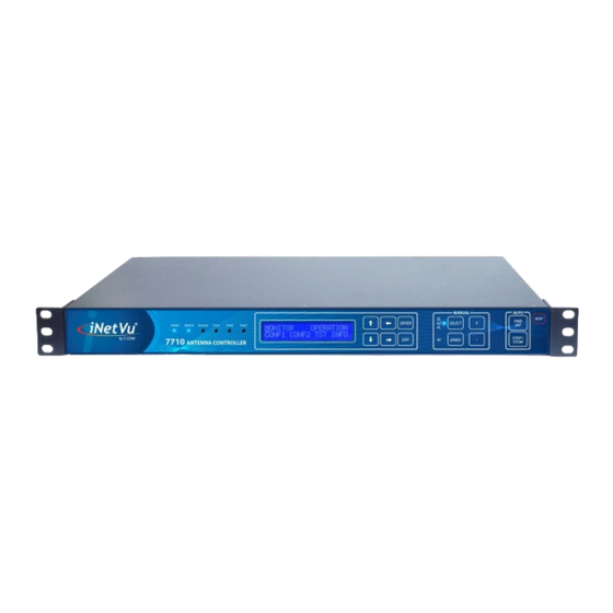
C-COM Satellite Systems Inc. 4. Physical Front View Automatic Front Panel Control LEDs Buttons Manual Control LCD Screen Buttons Reset Keypad Navigator Button GROUND 24 VDC COOLING POWER INPUT RX OUT PROTECT Power Input FANS 100-240 VAC Network Additional Receive... -
Page 12: Typical Connection Configuration
C-COM Satellite Systems Inc. 5. Typical Connection Configuration The typical connection configuration for each service will be the same regardless of the Satellite Modem / VSAT. However, the configuration parameters for Satellite Modem / VSAT Communication will differ depending on service. See iNetVu ®... -
Page 13: Typical Network Interface Connection
C-COM Satellite Systems Inc. 5.1. Typical Network Interface Connection GPS/Glonass Antenna iNetVu™ Fly-75V Platform COMBINED MOTOR *GROUND & DATA CONTROL PROTECTION CABLE External grounding connection 24 VDC Power Input (If external power source used and or required) 100 - 240VAC Combined Motor &... -
Page 14: Typical Usb Communication Interface
C-COM Satellite Systems Inc. 5.2. Typical USB Communication Interface GPS/Glonass iNetVu™ Fly-75V Antenna Platform *Ground protection COMBINED MOTOR & DATA CONTROL External CABLE grounding connection Network 24 VDC Power Cable Input (If external power source used and or 100 - 240VAC... -
Page 15: Typical Connection - Pc Free
C-COM Satellite Systems Inc. 5.3. Typical Connection – PC Free GPS/Glonass iNetVu™ 1201 Mobile Antenna Platform *Ground protection External grounding connection COMBINED MOTOR & DATA CONTROL CABLE RX IN RX OUT Network Cable 24 VDC Power Input (If external power source... -
Page 16: Installation
C-COM Satellite Systems Inc. 6. Installation ® ® The iNetVu 7710 Controllers are shipped pre-configured and calibrated with the iNetVu Mobile Platform (equipped with the 7720 Remote Drive Module) and service which you plan to use. Only configuration of the Satellite Modem / VSAT Communication parameters and the satellite you wish to find is required. - Page 17 C-COM Satellite Systems Inc. 2. Install the FTDI USB Driver and continue through the Installation Wizard. Click “Extract” Click “Next” Click “Finish” 3. Install the iNetVu ® 7710 Software by accepting defaults and close when complete. iNetVu™ 7710 Controller User Manual...
- Page 18 C-COM Satellite Systems Inc. 4. Connect the Controller using the provided USB cable. Windows Vista and 7+ users, the drivers should install automatically without any further user action. 5. You have successfully installed the 7710 iNetVu ® Drivers and Software. Exit the setup wizard.
-
Page 19: Setup
C-COM Satellite Systems Inc. 6.3. Setup 1. Connect all the cables and components as depicted in the previous section illustrating the setup schematics. Select connection that is best suited for your application. 2. Power on the iNetVu ® 7710 Controller. -
Page 20: Inetvu ® 7710 Front Panel Operation
C-COM Satellite Systems Inc. 7. iNetVu ® 7710 Front Panel Operation 7.1. LED DEFINITIONS Fig. 7: iNetVu 7710 Series Controller Front Panel LED Panel ® POWER - Solid light indicates power is ON. REMOTE - 7720 remote controller status. REMOTE LED will flash (Blue) every 1000ms if CANBUS and MODEM communication successful. -
Page 21: Manual And Automatic Controls Button Operation
C-COM Satellite Systems Inc. 7.2. Manual and Automatic Controls Button Operation Fig. 8: iNetVu ® 7710 Series Controller Front Panel Buttons How to Find Satellite Press “FIND SAT” Button. ® iNetVu Mobile Platform will automatically attempt to locate, lock, peak and enable the system onto the configured satellite beam or last satellite beam that locked on system. -
Page 22: Lcd Screen And Navigator Keypad Operation
C-COM Satellite Systems Inc. Note: powering on/off the 7710 Controller will also power off the 7720 Remote Drive Module which is located at the platform base. How to Reset the Controller Press “RESET” Button Power-cycles the iNetVu ® Controller DOES NOT reset default values 7.3. -
Page 23: Front Panel Menu Navigation Tree
C-COM Satellite Systems Inc. 7.4. Front Panel Menu Navigation Tree The following is a tree consisting of a list of the menu options available with the LCD interface. ® iNetVu 7710 Controller LCD Menu BEAM MONITOR OPERATION CONF TEST INFO ... -
Page 24: Supported Platforms
C-COM Satellite Systems Inc. MONITOR This menu branch allows the user to monitor the status of the iNetVu Fly-Away/Mobile Platform Axial Movement of EL, AZ, & PL, Target and Reference Satellites, displays information concerning the iNetVu 7710 Controller IP and the Satellite Modem / VSAT and Beacon status. - Page 25 C-COM Satellite Systems Inc. LCD Method 1. Advance to the CONF menu using the ‘←’ and ‘→’ arrows on the keypad. 2. Advance to “MT” using the ‘←’ and ‘→’ arrows and press the “Enter” key on the keypad. Select, Platform Type, Platform Version and enter Serial Number where the platform description appears (i.e.
-
Page 26: Monitor
(Modem and Beacon Receiver) Displays Modem status as well as the Beacon Receiver frequency and signal (if a beacon receiver is used) Displays IP of iNetVu 7710 Ethernet Port, and the VSAT modem. (Gateway) Displays Subnet, and Gateway IP. iNetVu™ 7710 Controller User Manual... -
Page 27: Main
C-COM Satellite Systems Inc. 7.7.1. MAIN This branch menu displays the real-time Elevation, Azimuth, Polarization Angles, their respective limits (Up, Down, Stow), the RF Receive Signal, Signal Strength, and the System Status. E-90.0 U D S A -45.7 S VV II P-34.6 S... - Page 28 C-COM Satellite Systems Inc. 5 – System Status (status meanings explained in the software section of this report) Azimuth Calibration ACP Testing Compass Calibration Dish Testing Idle Manual Movement Polarization Calibration Peaking (PA/PE) Positioning Searching Stowed 6 – Receive RF/DVB Signal Receive RF Signal as measured from the LNB.
- Page 29 C-COM Satellite Systems Inc. 7.7.2. Displays real-time current drawn and speed settings for the elevation motor, as well as real-time elevation angle and limits, offset, window size, and Elevation adjustment gap. E0.0 D U S I/S: 0-5 U D W: 5...
- Page 30 C-COM Satellite Systems Inc. 4 - Elevation Offset The number of degrees at which the iNetVu Mobile Software will offset the reading from the ® Inclinometer in order to produce an accurate (+/- 2°) Elevation Angle (e.g. O: 31 implies elevation offset of 31).
- Page 31 C-COM Satellite Systems Inc. 7.7.4. Displays real-time current drawn and speed settings for the polarization motor, as well as real- time polarization angle and limits, offset, and PL zero. P0.0 S I/S:0.0-2 L R O:0.0 Fig. 18: “PL” (Polarization) Display 1 –...
- Page 32 C-COM Satellite Systems Inc. 1 – GPS Status GPS Status is Valid, second V is for Velocity Status GPS Status has failed GPS Coordinates have been overridden 2 – GPS Coordinates Current Latitude Coordinate rounded to one decimal place in degree format.
- Page 33 C-COM Satellite Systems Inc. 2 – CP (Compass) Status Valid – The compass reading is functioning properly Override – the compass has been overridden, and direction entered manually considered Full Search – searches a full 360º search window. 3 – Compass Heading Displays Compass Heading after Compass has been read.
- Page 34 C-COM Satellite Systems Inc. 4 - Transponder Number (There are usually six (6) transponders for each satellite stored into the controller memory) 0 – 2 are horizontal Receive, and 3-5 are vertical receive) the user may overwrite the transponder data with his/her own (see configuration section).
- Page 35 C-COM Satellite Systems Inc. 3 - Transponder Number (for reference satellite) (There are usually six (6) transponders for each satellite stored into the controller memory) 0 – 2 are horizontal Receive, and 3-5 are vertical receive. The user may overwrite the transponder data.
-
Page 36: Hughes Modem Status (Only)
C-COM Satellite Systems Inc. 7.7.10. Hughes Modem Status (Only) SQ : 15 TC :24 RC :6 A :D BR :1448.05 0/0dB Fig. 24: Hughes Modem and Beacon Receiver 1 – Modem Communication Status, controller communication with the modem, INIT will appear if still initializing or no communication NA will appear if no modem selected. - Page 37 C-COM Satellite Systems Inc. 7.7.11. ® This menu displays the IP address of the user configured iNetVu 7710 Controller and Modem. (Ensure the IP address of the modem configured is the actual IP address of the modem, and that the 7710 Controller is operating on the same network as the modem) C_IP : 70.232.247.50...
-
Page 38: Operation
C-COM Satellite Systems Inc. 7.8. OPERATION LCD Menu options for available searchable satellite beams, enable transmitter, stow, controller restore to default settings and compass calibration routines and functions. Pressing on any option in the operation menu will trigger that command to be performed. - Page 39 C-COM Satellite Systems Inc. 2 – Stow Moves the system to a position where the AZ is zeroed triggering the AZ limit switch and then moving on the EL axis in the up or down direction depending on the configured system. The EL UP or EL ST Limit switches are turned on when movement on EL axis completes.
-
Page 40: Beam
C-COM Satellite Systems Inc. 7 – Restore Compass Factory Calibration (CPR) Restores the compass to factory calibration. Ensure the compass is levelled/flat when restoring to factory calibration for optimum results. 8 – Stop Stops the current operation. 7.9. BEAM The LCD Configuration Interface is password protected. -
Page 41: Sat
C-COM Satellite Systems Inc. 7.9.1. 009.0E - 0 INC:D REF:D BM01_072W Fig. 29: Beam and orbital Configuration 1 – Target Satellite Beam ID 2 – Target longitude and Hemisphere 3 – Transponder number Horizontal Receive (0-2), Vertical Receive (3-5) 4 – Reference Satellite D –... -
Page 42: Dvb
C-COM Satellite Systems Inc. 7.9.2. 1468.7 50000 VH+00.0 AUTO D 10.75 Fig. 30: DVB Configuration Display 1 – Transponder Frequency (MHz) 2 – Transponder Symbol Rate (Ksps) 3 – Transponder polarity (TX & RX) TX here is vertical and RX is horizontal polarity (VH) 4 –... -
Page 43: Sr_Cp
C-COM Satellite Systems Inc. The default value should be set to 10.75, the user is not required to change this value unless necessary, otherwise select the carrier from the table or enter one if not listed. 9 - LNB Power (Target Satellite) - Page 44 C-COM Satellite Systems Inc. 3 – Compass Heading Compass Heading after Compass has been read. Approximate Headings: North 354 East 87 South 176 West 4 - AZ Search Window The Search Window is the area of the sky which the iNetVu ®...
-
Page 45: Conf
C-COM Satellite Systems Inc. 7.10. CONF ® This Menu will allow the user to select and set the configuration of the iNetVu System as well as the Reference satellite option. The target and the reference satellite(s) can be selected and set from the pre-configured list. -
Page 46: Sat
C-COM Satellite Systems Inc. 7.10.1. This menu allows for the configuration of the target satellite(s) and the reference satellite. MSS:D BM01_072.0W Fig. 34: Target Satellites display 1 – Multiple Satellite Search This feature when enabled will allow the search to be carried out on three listed target satellites. The search will automatically switch to the next listed target if the previous target search fails. - Page 47 C-COM Satellite Systems Inc. C – Read Modem Frequency, Symbol Rate etc… from the controller configuration. B – Read Modem Frequency, Symbol Rate etc… from the Configuration Table. M – Read Modem Frequency, Symbol Rate etc… from the modem. 2 – Configured Satellite Modem Receive Frequency in MHz with no decimals (HNS Only).
- Page 48 C-COM Satellite Systems Inc. 7.10.4. The AZ menu allows configuration of compass offset. CP_O: +00 1 – Compass Offset A fixed offset could be used to adjust the compass heading. This value would be added to the calculated compass heading to compensate for any consistent inaccuracy of the compass reading.
- Page 49 C-COM Satellite Systems Inc. 1 – GPS Status Configuration Use Coordinates from GPS Antenna Override GPS and use the coordinates entered (2) and (3). Enables the GPS coordinates to be manually overridden. This should only be enabled in the event that the GPS Antenna is malfunctioning and the user has a reliable, alternate source for coordinates.
- Page 50 C-COM Satellite Systems Inc. 2 – Platform Version Number The user must select the platform version type to ensure the correct configuration parameters and settings are referenced when operating the system. The platform version when selected will differentiate hardware and software configuration on New Generation platforms which may affect the operation.
- Page 51 C-COM Satellite Systems Inc. c) NMEA This option allows the user to communicate and output GPS readings/values from the 7710 Controller via COM Port (RS232) connection. The default baud rate is 9600. d) DBUG-19200 (internal use only) 2 – Unattended Operation This option is used for remote operations where system is left unattended as the name indicates, mainly for unmanned sites.
- Page 52 C-COM Satellite Systems Inc. 5 – Motion Protection iNetVu Platform will automatically stow if the antenna detects extreme motion, such as severe ® shaking caused by poor weather conditions. If the shaking/shift is in small increments the system will not stow assuming signal is not lost. If the small motion/movement count (12 small movements in 30 seconds) logged in a specific time window exceeds the set threshold the system will re-peak if signal exists or stow if signal lost.
- Page 53 C-COM Satellite Systems Inc. 7.10.11. This menu will allow the user to configure the controller IP address, as well as the Modem IP address. C_IP : 192.168.0.3 M_IP: 192.168.0.1 Fig. 41: IP Configuration 1 – iNetVu ® 7710 Controller’s IP Address 2 –...
-
Page 54: Test
C-COM Satellite Systems Inc. Orbital Slot of Satellite Receive Polarization DVB Type L-Band or Ku-Band Rx Frequency (kHz) Symbol Rate (ksps) FEC Code Rate NA – Sub-ID Choose Typical for normal operation or select one of the custom created files when using multiple beacon satellite search. -
Page 55: E&A&P
C-COM Satellite Systems Inc. E&A&P Will allow for Demo Testing on all axes (elevation, azimuth, and polarization) for a user specified angle range. DPLY Deploys the antenna to a user specified azimuth, elevation, and polarization position. DPLY_C Will read the compass heading at a user specified elevation, azimuth, and polarization target point. -
Page 56: Dply
C-COM Satellite Systems Inc. 4 – Axis Selection and looping option The first two characters refer to the axis selection (i.e. DD: D). Disable Test for all axes Perform test on the Elevation axis only Perform test on the Azimuth axis only Perform test on the Polarization axis only Perform tests on all the axes. -
Page 57: Dply_C
C-COM Satellite Systems Inc. 4 – Deploy Automatically moves antenna to the manually entered Elevation, Azimuth and Polarization angles. 7.11.3. DPLY_C E: +20 P+60 A +180 CP_T Fig. 46: Deploy Compass Reading Angles 1 – Elevation Movement User-defined target elevation angle offset for compass reading 2 –... -
Page 58: A_Acp
C-COM Satellite Systems Inc. 7.11.4. A_ACP Initiates an automatic cross-pol test. 7.11.5. M_ACP Initiates a Manual cross-pol test. 7.11.6. S_ACP Stops the cross-pol testing instantly. 7.12. INFO ® Displays information regarding the iNetVu 7710 Controller’s firmware, software versions and MAC address information, the Mobile Platform type currently configured, and also any Error Codes detected. -
Page 59: Cc1
C-COM Satellite Systems Inc. 7.12.1. This branch menu displays the Central Controller ID (serial number), Hardware Version, Firmware, and Boot loader Version ID: 17005 SQT: 31 FBV: 7.7.1.0—7.3.3.0 Fig. 48: “CC1” (Controller Info) Display 1 – Controller ID Number The iNetVu ®... -
Page 60: Dvb_D
C-COM Satellite Systems Inc. 2 – iNetVu ® 7720 Remote Drive Module Firmware and Boot loader version. The firmware version is to the left of the dash (i.e. 7.7.1.0 - 7.3.2.0), and the boot loader version is to the right of the dash (i.e. 7.7.1.0 - 7.3.2.0). -
Page 61: Sys
C-COM Satellite Systems Inc. 7.12.5. This menu displays platform type, hardware version, serial number and data recording file size. A0986A--01.X SN13435 R:16024 Fig. 52: “SYS” (Platform) information Display 1 – Indicates platform type and platform hardware version number. 2 – Data recording information(C-COM internal use). -
Page 62: Inetvu ® 7710 Software
C-COM Satellite Systems Inc. 8. iNetVu ® 7710 Software ® ® The iNetVu Mobile Software plays an integral role in connecting the operator/user and iNetVu Mobile System. It has the ability to communicate with the Satellite Modem, automatically find and lock onto a satellite (Beam) and stow the antenna when completed. The user has the option to search for satellite using the following methods, DVB search;... -
Page 63: Navigating Menus
C-COM Satellite Systems Inc. The Wizard will check Firmware and Software versions if “Yes” is selected to validate the versions are the same and prompt the user to update the Firmware if they are different. Both the 7710 Controller and the 7720 Remote Drive Module will be validated. - Page 64 C-COM Satellite Systems Inc. Fig. 55: Controls Menu Signal Strength A real-time Signal Quality Factor (SQF). A value obtained from the Satellite Modem when locked onto a signal. Using a red/yellow/green color-coated system, it denotes the strength of the received signal from the current satellite.
- Page 65 C-COM Satellite Systems Inc. The Isolation Value will correspond to the transmit quality of an HNS system. Otherwise, this field is not applicable. Fig. 57: Isolation Value Display Date/Time Current date and time as received from the GPS/Glonass Antenna. Should the GPS/Glonass experience any problems, the alternate source is your PC internal date and time.
- Page 66 C-COM Satellite Systems Inc. Stow Antenna Re-centers the antenna and lowers it into the stowed position. Note: The “stow” command for the Fly-away platforms moves the Platform to a home position. Stop Operation ® Halts all motor movements and disrupts all communication between iNetVu Mobile/Fly-Away System components.
- Page 67 C-COM Satellite Systems Inc. When the Elevation STOW Limit Indicator is ON for the Fly-75V or Fly-98G/H Fly-Away or Drive-Away systems, it is indicated by the “UP/LP” in the EL Limit Switch field. ® Elevation Angle will be “+92 ±1.0” degrees, to denote that the iNetVu Fly-away Platform is now stowed or at the home position.
- Page 68 C-COM Satellite Systems Inc. Enable/Disable Transmitter Automatically Enables or Disables the Transmission process. Background will turn grey when transmitter is disabled and green when the transmitter is enabled. Enable/Disable ACP Enables or Disables the ACP (Automatic Cross-Pol Testing), and Manual Cross-Pol Testing.
- Page 69 C-COM Satellite Systems Inc. Duration Length of time of Manual Movement using increments of 50ms i.e. duration time of movement - 1 x 50ms = 50ms Speed Motor Speed of Manual Movement 1 = Slowest, 9 = Highest Fig. 64:...
- Page 70 C-COM Satellite Systems Inc. Remote Temp (Deg) Monitors and displays Remote Controller’s temperature Target Satellite parameters Target Antenna Elevation Angle Target theoretical Elevation Angle Target Antenna Azimuth Angle (0 to ± 180) Target theoretical Azimuth Angle (0 to 360) Target Antenna Polarization Angle (0 to ± 90) Target theoretical Polarization Angle Fig.
- Page 71 C-COM Satellite Systems Inc. Target Polarization (Target PL) The Target Polarization Angle is a calculated value based on the Antenna’s GPS information and Satellite Longitude. Polarization is disabled and displays “DDD” for none motorized Polarization Axis Compass Heading Orientation of the Mobile and Fly-Away Platforms.
- Page 72 C-COM Satellite Systems Inc. Message Panel Displays real-time status updates, system messages, and error codes. Fig. 67: Message Panel Status Panel The Status Panel describes system operations that are either imminent, taking place, or the current status of that component. The Status Panel is located at the bottom of the Controls menus, and has a set of six message blocks, respectively.
- Page 73 C-COM Satellite Systems Inc. System Status Displays current system environment System Idle No operations are currently being performed. ACP Testing ACP Testing is being performed. Skew Adjusting Polarization adjustment to adjust the polarization axis for any vehicle inclination. The Azimuth Axis will rotate 90º...
- Page 74 C-COM Satellite Systems Inc. GPS Failed GPS signal is not being received from the GPS Antenna. GPS Override GPS coordinates have been manually overridden from the Maintenance menu. Controller Status Displays communication status between the PC and the iNetVu ®...
-
Page 75: Maintenance
C-COM Satellite Systems Inc. 8.2.2. Maintenance The Maintenance menu allows users to configure the communication between the controller and platform type, as well as various system parameters for optimal performance. Separate tabs have been added to set apart the 3 axis as well as GPS and Compass for easier configuration. - Page 76 C-COM Satellite Systems Inc. 8.2.2.1 Platform Parameters Fig. 70: Maintenance Platform Parameters Type The user is capable of configuring the platform type in use via the controller front panel or the software application. The firmware/software application will a different name schema under platform type in the drop down than the one provided in the marketing datasheets.
- Page 77 C-COM Satellite Systems Inc. Platform Serial Number The user will be required to enter the last five-digits of the platform serial number located next to the connector plate on the iNetVu ® Mobile Platform. Fig. 71: Platform Identification Platform Hardware Version This field identifies hardware changes in the New Generation platform types.
- Page 78 C-COM Satellite Systems Inc. Polarization Offset (PL) By default this polarization-offset value is set to 0°. If there happens to be a requirement for a polarization offset, the user may manually enter this value in this area. This area is also updated automatically if the skew adjustment procedure recognizes an incline which will adjust the target polarization angle.
- Page 79 C-COM Satellite Systems Inc. Single Satellite Search Multiple Satellite Search 8.2.2.5 GPS Fig. 72: Maintenance – GPS Parameters GPS Override Checkbox Enables the GPS coordinates to be manually overridden. This should only be enabled in the event that the GPS Antenna is malfunctioning and the user has a reliable, alternate source for coordinates. If this box is checked, the GPS coordinates should be manually entered in the ‘GPS Lat’, and the ‘GPS Lon’...
- Page 80 C-COM Satellite Systems Inc. 8.2.2.6 Operation Mode Unattended Operation This option is used for remote operations where system is left unattended as the name indicates, mainly for unmanned sites. This feature must not be used when the iNetVu system is being moved around or in transport mode.
- Page 81 C-COM Satellite Systems Inc. location change plus a variation of 2 degrees or more on Elevation. Overriding GPS will omit this feature and antenna stowing due to movement will not occur. 8.2.2.7 Compass (Maintenance) These buttons provide the operator the ability to validate the compass functionality and as well the correct values at the four locations.
- Page 82 C-COM Satellite Systems Inc. Check CP (Only Applicable on 1201 & 1801) Tests the compass’ heading and accuracy by rotating the antenna at 90 intervals and comparing the compass readings with the actual antenna’s movement to the 4 positions (0, 90, 180, 270) The mount and or Mobile Platform Vehicle must be pointed North (Vehicle front windshield).
- Page 83 C-COM Satellite Systems Inc. Restore Compass (Applicable on All) Restores the compass to its factory calibrated state. 8.2.2.8 Maintenance Menu Buttons The following buttons are available in the maintenance menu for multiple purposes including, ease of use, troubleshooting, accessing of data files and more.
-
Page 84: Maintenance Test (Demo Window)
C-COM Satellite Systems Inc. 8.2.3. Maintenance Test (Demo Window) ® Used for system tests, trouble-shooting, and for demonstrating the iNetVu Mobile System. This feature is accessible from the Maintenance Window Test button. Start Angles Initial values for the test/demo sequence. - Page 85 C-COM Satellite Systems Inc. Test EL/AZ/PL Moves and rotates to the values set in the Start Angle and End/Demo Angle fields. Test Compass Positions Antenna to the set Elevation angle and updates compass heading by moving to the set End Angle values entered by the user on all three axis. Only end angles are required when testing or validating compass.
-
Page 86: Configuration
C-COM Satellite Systems Inc. 8.2.4. Configuration The Configuration menu allows users to configure the communication medium between the Satellite Modem, Controller (ACU) and iNetVu ® Mobile Software, as well as various System parameters for optimal performance. Users have the ability to configure and save 64 Satellites (1-65) with their orbital slot. - Page 87 C-COM Satellite Systems Inc. 8.2.4.1 Beam Configuration Fig. 74: Configuration – Beam Parameters Beam ID. 64 different satellite Beam ID are configurable on same or different satellites allowing users to configure and save for easy access. Currently only 16 Beam ID are configurable.
- Page 88 C-COM Satellite Systems Inc. LNB Power (V) In cases where the LNB requires more power than the modem can provide, or if the user would like to power the LNB from the controller, or if the user would like to find satellite without the use of a modem,...
- Page 89 C-COM Satellite Systems Inc. TR No. (Transponder Number) There are Six (6) Transponder values in the 7710 Controller for each satellite. Transponder (0-2) are horizontal receive Transponder (3-5) are vertical receive. The user may override the default values saved in the controller with his/her transponder information...
- Page 90 C-COM Satellite Systems Inc. 8.2.4.3 Modem Parameters Configurable parameters will differ depending on the type of modem service selected under the type field. Refer to iNetVu Modem Quick Starts for detailed configuration and setup pertaining to your modem type and service.
- Page 91 C-COM Satellite Systems Inc. Modem Delay The user may increase the delay time when polling for modem signal by adjusting this number. Increasing this number, will increase the time to find and lock on to satellite as it slows down controller activity and allows slower modems to catch up.
- Page 92 C-COM Satellite Systems Inc. HNS_Ku Modem Options: The Hughes modems will have additional configurable fields such as frequency, symbol rate, polarization, etc… that are required on the modem side in order to find satellite. These settings must match the controller side configuration in order for the modem to successfully lock and stay connected on satellite after TX is enabled.
- Page 93 C-COM Satellite Systems Inc. Hemisphere Hemisphere the modem is operating in, For instance, North American operating modems would be set to “W”, representing western hemisphere. LNB 22 KHz Tone The option on the modem side must match the status option on the DVB Transponder side. The 22 KHz tone can be disabled or enabled for supporting modems that allow for acquisition with LNBs that switch frequency ranges by adjusting the 22 KHz tone.
- Page 94 C-COM Satellite Systems Inc. HNS_KA Modem options Hughes Ka service modem will automatically propagate and fill in all the fields except the IP and longitude when BEAM_T mode is selected. Parameters are generally the same as the HNS_KU service type.
- Page 95 C-COM Satellite Systems Inc. DVB Type Required on Hughes Ku (HX Modem) the DVB-S type of the modem to be set to allow the modem to stay online after the TX enable command has been sent from the controller. If the DVB-S type on the modem is not set to the same as the controller (default used is DVB-S1) the communication will be lost after modem goes online.
- Page 96 C-COM Satellite Systems Inc. finding the transponder data for a specific satellite, or if no transponder data exists. The controller will then peak on the modem signal when the satellite is found. RF search should be used as a last resort after DVB and or DVB with reference satellite.
- Page 97 C-COM Satellite Systems Inc. 5: Re-peak every 3 hours 6: Re-peak every 4 hours 7: Re-peak every 6 hours 8: Re-peak every 8 hours 9: Re-peak every 12 hours 8.2.4.5 Compass (Search) Full Search Performs a full 360º Azimuth search for the desired Satellite. This process may take up to 30 minutes to find and lock onto Satellite.
- Page 98 C-COM Satellite Systems Inc. Beacon Freq (MHz) This field represents the frequency that the Optional Beacon Receiver is programmed for. The user may change this frequency to whatever Beacon is required for the target satellite. 64 configurable Beacon frequency maybe configured with 64 Beam ID, thus providing the user 64 target satellites to choose from.
- Page 99 C-COM Satellite Systems Inc. Enable Beep This drop box is used to either enable or disable the beeping noise when navigating the LCD interface on the iNetVu ® 7710 Controller. Selected option implies beeping sound is enabled unless D (disabled) is selected.
-
Page 100: About
C-COM Satellite Systems Inc. 8.3. About Displays information to the user about various sub-system components, as well as contact information for support and feedback. Fig. 79: About Menu Software Version iNetVu ® Mobile Software version Build ID Date of software release... - Page 101 C-COM Satellite Systems Inc. 7710 Controller Firmware iNetVu ® Controller’s firmware version. For compatibility purposes, Controllers are pre-configured with the appropriate firmware for the accompanied software version. Serial Number iNetVu ® Controller Serial Number. Interface This field represents the means of communication between the iNetVu ®...
- Page 102 C-COM Satellite Systems Inc. Type Mobile Platform type. Serial Number(S/N) Mobile Platform serial number. Version Mobile Platform hardware version. Satellite Longitude Orbital slot of Satellite that is currently configured and used by the Beam. Polarity Satellite polarity, polarization is based on receive (RX) polarity.
-
Page 103: Setup Wizard
C-COM Satellite Systems Inc. 8.4. Setup Wizard The Setup Wizard has been implemented to aid first time users in configuring their system after the software has been installed. A Pop-up window will show at first launch allowing the user to use the Setup Wizard (select Yes) or to bypass it (select No) and use it at a later time. -
Page 104: Language
C-COM Satellite Systems Inc. 8.5. Language The multilingual feature allows the toggling between Six (6) languages and updates in real-time the selected language. Currently the available languages are English, Chinese (Simplified and Traditional), Spanish, Russian and Swedish with others to come. -
Page 105: Inetvu ® 7710 Series Controller Web Interface
C-COM Satellite Systems Inc. 9. iNetVu ® 7710 Series Controller Web Interface Another method of communicating remotely with the 7710 Controller is through the web interface. It has the ability to communicate with the Satellite Modem, automatically find and lock onto a satellite and stow the antenna when completed. -
Page 106: Admin
C-COM Satellite Systems Inc. 9.1.1. ADMIN This is the login page (default password: “password”). Fig. 81: Web Interface – Login Page To reset the password, click on “RESET PWD”, and enter “123456789” for the reset ID. Fig. 82: Web Interface – Login Password Reset Page... - Page 107 C-COM Satellite Systems Inc. These options are available once the controller is in upload mode (Firmware, Sat Table etc...). LOGIN CONTROLLER UPDATE RESET CONTROLLER Fig. 83: Web Interface – S File Uploading Login Screen Once the controller is in upload mode (reset controller and depress the up and down keys on 7710 front panel).
-
Page 108: Controls
C-COM Satellite Systems Inc. 9.1.2. CONTROLS ® Similar to the iNetVu 7710 Software Controls Menu, the Web Interface Controls window allows the user to monitor system operations, and perform automatic as well as manual system functions. Fig. 84: Web Interface - Controls Screen... -
Page 109: Controller
C-COM Satellite Systems Inc. 9.1.3. CONTROLLER The Controller configuration allows users to configure the communication medium between the Controller and iNetVu ® 7710 Web Interface, as well as various System parameters for optimal performance. Fig. 85: Web Interface – Controller Configuration Screen... -
Page 110: Beam
C-COM Satellite Systems Inc. 9.1.4. BEAM The Configuration menu allows users to set the Beam ID, Satellite parameters, orbital slot, and override parameters. Fig. 86: Web Interface – Beam Configuration Screen iNetVu™ 7710 Controller User Manual... -
Page 111: Modem
C-COM Satellite Systems Inc. 9.1.5. MODEM Satellite Modem service type selection, and modem parameter configuration that include and are not limited to disable/enable options for ACP, TX_DIS, TX, RX, BC and 22k. Service sub id for multiple beacon satellite search under NA, choose Typical for normal operation or select one of the custom Configurations that have been created. -
Page 112: Test
C-COM Satellite Systems Inc. 9.1.8. TEST This menu option is mainly used for Demos and testing certain components of the system, as well as for sending certain modem commands that have been integrated with the iNetVu ® 7710 Controller. The Compass Calibration functions are now also found on this screen. -
Page 113: About
C-COM Satellite Systems Inc. 9.1.9. ABOUT The “iNetVu About” web page, displays information to the user about various sub-system components for the 7710 and 7720 controllers, as well as contact information for support and feedback. Fig. 90: Web Interface - About Screen... -
Page 114: Appendix
C-COM Satellite Systems Inc. Appendix iNetVu™ 7710 Controller User Manual... -
Page 115: Appendix 1: Default Limits And Configuration Data Tables
C-COM Satellite Systems Inc. 10.1. Appendix 1: Default Limits and Configuration Data Tables Compass Reading Elevation PLATFORM TYPES Fly-75V Fly-98G/H/V Fly-981 1201-J Fly-1801 (A0756A) (A0986A/B) (A0986C) (A1201A) (A1801A) COMPASS READING ELEVATION Table 1: Compass Reading Elevation Default Values Elevation Offset... -
Page 116: Appendix 2: Compass Direction And System Ref. Az Table
C-COM Satellite Systems Inc. 10.2. Appendix 2: Compass Direction and System Ref. AZ Table System Ref. Direction Search Window Starting Angle North (N) = 0 North West (NW) = 45 East (E) = 90 South East (SE) = 135 -135... -
Page 117: Appendix 3: Updating Firmware On 7710&7720 Controllers
Power ON the PC and the 7710 Controller which will also provide power to 7720 (it is assumed that the Power&Data cable is connected to 7720 remote controller). Open the iNetVu 7710 Controller Software Connect the PC to the Controller through a USB interface. -
Page 118: Appendix 4: System Configuration Using Setup Wizard
C-COM Satellite Systems Inc. 10.4. Appendix 4: System Configuration Using Setup Wizard The Setup Wizard will launch every time the iNetVuMobile7700 software is executed, select “Do not show this message again” to allow software to go straight to the Controls Window when the software application is launched. - Page 119 C-COM Satellite Systems Inc. 4. The Setup Wizard will check and ensure Firmware and Software versions are the same, if not the same version you will be prompted to update, select Yes. 5. Put controller in firmware update mode by following instructions on the screen.
- Page 120 C-COM Satellite Systems Inc. Firmware update status will be displayed on bottom of screen. The wizard will resume after 7710 Firmware update completes. The wizard will prompt you to update the 7720 firmware after the 7710 firmware update finishes. Click OK and put the controller in firmware update mode.
- Page 121 C-COM Satellite Systems Inc. 9. Click “Update Firmware for 7720” button. Controller will reset after firmware update completes and the wizard will automatically flip to the next screen. iNetVu™ 7710 Controller User Manual...
- Page 122 C-COM Satellite Systems Inc. 10. Select and or enter Platform type, version and Serial number and click Next. iNetVu™ 7710 Controller User Manual...
- Page 123 C-COM Satellite Systems Inc. 11. Select the service type (Modem service used), and interface, along with Controller and Modem information. Hover over each field to get tips, examples and clear explanation. Click Next. iNetVu™ 7710 Controller User Manual...
- Page 124 C-COM Satellite Systems Inc. 12. Satellite information screen, allows user to configure Satellite, Search Method and DVB settings. Enter and select Parameters/Settings for the Satellite used with your platform. Click Finish. 13. Click Yes to save and exit. 14. Launch the Application by double clicking the iNetVuMobile7710 icon.
-
Page 125: Appendix 5: Dc Input Power Cable Connectivity
C-COM Satellite Systems Inc. 10.5. Appendix 5: DC Input Power Cable Connectivity Controller Receptacle External Cable Plug J1 Panel Receptacle P1 Straight Plug 4-Socket Contacts Mating View 4-Pin Contact Mating View P1 External Cable Plug Pin List (4-CONTACTS) RECEPTACLE SIGNAL... - Page 126 C-COM Satellite Systems Inc. Materials Required for External Cable: Part # Quantity Discription 206429-1 TEConnectivity AMP CPC Plug Assembly, Shell Size 11, Reverse Sex, 4-Pin Contacts, Series 1 206358-5 TEConnectivity AMP CPC Cable Clamp, Size 11 66361-4 TEConnectivity AMP CPC Pin Contact, Series 1, Wire 18-...
-
Page 127: Appendix 6: Declaration Of Conformity
C-COM Satellite Systems Inc. 10.6. Appendix 6: Declaration of Conformity iNetVu™ 7710 Controller User Manual...