Table of Contents
Advertisement
QQ
3 7 63 1515 0
SERVICE MANUAL
Ver. 1.3 2005. 05
AUDIO POWER SPECIFICATIONS (US MODEL)
POWER OUTPUT AND TOTAL HARMONIC DISTORTION
200 watts per channel minimum continuous average power into
4 ohms, both channels driven from 20 Hz to 20 kHz with no more
than 0.1% total harmonic distortion per Car Audio Ad Hoc
Committee standards.
TE
L 13942296513
Other Specifications
Circuit system
OTL (output transformerless) circuit
Pulse power supply
Inputs
RCA pin jacks
High level input connector
Outputs
Speaker terminals
Through out pin jacks
Suitable speaker impedance
2 – 8 Ω (stereo)
4 – 8 Ω (when used as a bridging amplifier)
Maximum outputs
400 W × 2 (at 4 Ω)
600 W × 2 (at 2 Ω)
1,200 W (monaural) at 4 Ω
Rated outputs (supply voltage at 14.4 V)
200 W × 2 (20 Hz – 20 kHz, 0.1% THD,
at 4 Ω)
250 W × 2 (20 Hz – 20 kHz, 0.15% THD,
at 2 Ω)
500 W (monaural) (20 Hz – 20 kHz, 0.15% THD,
at 4 Ω)
Frequency response
5 Hz – 50 kHz (
Input level adjustment range
0.3 – 6.0 V (RCA pin jacks)
1.2 – 12.0 V (High level input)
www
.
Sony Corporation
9-961-370-04
2005E04-1
e Vehicle Group
© 2005. 05
Published by Sony Engineering Corporation
http://www.xiaoyu163.com
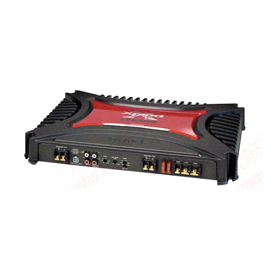
XM-2200GTX
+0
dB)
–3
x
ao
u163
y
i
http://www.xiaoyu163.com
2 9
8
SPECIFICATIONS
Q Q
3
6 7
1 3
1 5
Low-pass filter
Low boost
Power requirements
Power supply voltage
Current drain
Dimensions
Mass
Supplied accessories
Design and specifications are subject to change without
notice.
STEREO POWER AMPLIFIER
co
.
9 4
2 8
US Model
Canadian Model
AEP Model
UK Model
E Model
0 5
8
2 9
9 4
2 8
50 – 300 Hz, –12 dB/oct
0 – 10 dB (40 Hz)
12 V DC car battery
(negative ground)
10.5 – 16 V
at rated output : 48 A (at 4 Ω)
Remote input : 1 mA
Approx. 400 × 55 × 276 mm
(15
× 2
× 10
in.)
3/4
1/4
7/8
(w/h/d) not incl. projecting parts and controls
Approx. 4.6 kg (10 lb. 6 oz.) not incl. accessories
Mounting screws (4)
High level input cord (1)
Protection cap (1)
m
9 9
9 9
1
Advertisement
Table of Contents

Related Manuals for Sony XM-2200GTX


Summary of Contents for Sony XM-2200GTX
- Page 1 5 Hz – 50 kHz ( –3 Input level adjustment range 0.3 – 6.0 V (RCA pin jacks) 1.2 – 12.0 V (High level input) STEREO POWER AMPLIFIER u163 Sony Corporation 9-961-370-04 2005E04-1 e Vehicle Group © 2005. 05 Published by Sony Engineering Corporation http://www.xiaoyu163.com...
-
Page 2: Table Of Contents
LES COMPOSANTS IDENTIFIÉS PAR UNE MARQUE 0 SUR LES DIAGRAMMES SCHÉMATIQUES ET LA LISTE DES PIÈCES SONT CRITIQUES POUR LA SÉCURITÉ DE FONCTIONNEMENT. NE REMPLACER CES COMPOSANTS QUE PAR DES PIÈCES SONY DONT LES NUMÉROS SONT DONNÉS DANS CE MANUEL OU DANS LES SUPPLÉMENTS PUBLIÉS PAR SONY. http://www.xiaoyu163.com... -
Page 3: General
XM-2200GTX SECTION 1 GENERAL 3 7 63 1515 0 This section is extracted from instruction manual. Features Caractéristiques Low boost Amplification de basses fréquences • Maximum power output of 400 W per channel • Puissance de sortie maximale de 400 W par canal (at 4 Ω). -
Page 4: Connections
XM-2200GTX 3 7 63 1515 0 Connections Connexions 2-Speaker System Système à 2 haut-parleurs Caution Attention For details on the settings of switches and Car audio • Before making any connections, disconnect • Avant d’effectuer les connexions, débranchez controls, refer to “Location and Function of Autoradio Controls.”... - Page 5 XM-2200GTX 3 7 63 1515 0 Dual Mode System (With a Bridged Subwoofer) 2-way System Double mode de connexion (avec un haut-parleur Système 2 voies d’extrêmes graves en pont) Two output channels Deux canaux de sortie LINE OUT Car audio...
- Page 6 XM-2200GTX 3 7 63 1515 0 High Level Input Connection (2-Speaker System) Connexion d’entrée à haut niveau (Système à 2 haut-parleurs) White Left speaker output Blanc Sortie haut-parleur gauche Black-striped cord Car audio Cordon rayé noir Autoradio Gray Right speaker output...
-
Page 7: Disassembly
XM-2200GTX SECTION 2 DISASSEMBLY 3 7 63 1515 0 Note : This set can be disassemble according to the following sequence. 2-1. BOTTOM PLATE (Page 7) 2-2. MAIN BOARD SECTION (Page 8) 2-4. LED BOARD 2-3. MAIN BOARD (Page 9) (Page 8) Note : Follow the disassembly procedure in the numerical order given. -
Page 8: Xm-2200Gtx Qq
XM-2200GTX 3 7 63 1515 0 2-2. MAIN BOARD SECTION screw 3 x 8) three screws three screws 3 x 8) 3 x 8) 1 four screws 3 x 8) 5 MAIN board section heat sink (main) 6 CN810 L 13942296513 2-3. -
Page 9: Led Board
XM-2200GTX 3 7 63 1515 0 2-4. LED BOARD screw 2 LED board (+BT 3 x 6) light guide plate heat sink (main) L 13942296513 u163 http://www.xiaoyu163.com... -
Page 10: Electrical Adjustment
XM-2200GTX SECTION 3 ELECTRICAL ADJUSTMENT 3 7 63 1515 0 Bias Adjustment Note : In Bias Adjustment, adjust RV103 if any of Q108 through Q113 are replaced. Adjust RV203 if any of Q208 through Q213 are replaced. Condition : This adjustment should be performed about one minute after the remote mode is turned on at a room tempera- ture of about 25°C. -
Page 11: Diagrams
XM-2200GTX SECTION 4 DIAGRAMS 3 7 6 3 1 5 1 5 0 4-1. BLOCK DIAGRAM S801-1 PRE AMP PRE AMP FILTER IC101 (1/2) CNJ801-1,-3 IC102 (1/2) LOW BOOST LINE INPUT IC102 (2/2) (BTL) SWITCH CN804 Q102 DIFFERENTIAL DRIVE... -
Page 12: Schematic Diagram –Main Section (1/2)
XM-2200GTX 3 7 6 3 1 5 1 5 0 4-2. SCHEMATIC DIAGRAM — MAIN SECTION (1/2) — • Refer to page 15 for Common Note on Schematic Diagrams and IC Block Diagram. IC101(1/2) CNJ801 C101 IC102(1/2) C111 R101... -
Page 13: Schematic Diagram -Main Section (1/2)
XM-2200GTX Ver. 1.1 3 7 6 3 1 5 1 5 0 4-3. SCHEMATIC DIAGRAM — MAIN SECTION (2/2) — R135 C124 R131 R147 R801 C801 R155 Q112 IC102(2/2) Q105 R145 R800 Q103 Q110 R150 R143 D801 RV103 Q108... -
Page 14: Printed Wiring Boards -Main Section
XM-2200GTX 4-4. PRINTED WIRING BOARDS — MAIN SECTION — • Refer to page 15 for Common Note on Printed Wiring Boards and Semiconductor Location. 3 7 6 3 1 5 1 5 0 TP23 Q804 L905 Q212 Q210 TH808... - Page 15 XM-2200GTX 3 7 63 1515 0 • Semiconductor Location (MAIN BOARD) THIS NOTE IS COMMON FOR PRINTED WIRING BOARDS Ref. No. Location Ref. No. Location AND SCHEMATIC DIAGRAMS. D104 F-11 Q106 E-10 (In addition to this, the necessary note is...
-
Page 16: Exploded Views
XM-2200GTX SECTION 5 EXPLODED VIEWS 3 7 63 1515 0 NOTE: • The mechanical parts with no reference • Color Indication of Appearance Parts The components identified by mark 0 or dotted line with mark number in the exploded views are not supplied. -
Page 17: Main Board Section
XM-2200GTX Ver. 1.2 3 7 63 1515 0 5-2. MAIN BOARD SECTION not supplied Q209,210,213 Q109,110,113 Q208,211,212 not supplied Q108,111,112 L 13942296513 Ref. No. Part No. Description Remark Ref. No. Part No. Description Remark 3-262-163-01 PANEL, FRONT Q109 X-3383-028-1 FET PAIR ASSY (P) (IRF9540) (set of 3) -
Page 18: Electrical Parts List
XM-2200GTX SECTION 6 MAIN ELECTRICAL PARTS LIST 3 7 63 1515 0 NOTE: • Due to standardization, replacements in • Items marked “*” are not stocked since The components identified by mark 0 or dotted line with mark the parts list may be different from the they are seldom required for routine service. - Page 19 XM-2200GTX MAIN 3 7 63 1515 0 Ref. No. Part No. Description Remark Ref. No. Part No. Description Remark C906 1-164-161-11 CERAMIC CHIP 0.0022uF 10% 100V D208 8-719-016-74 DIODE 1SS352 C907 1-126-786-11 ELECT 47uF D209 8-719-016-74 DIODE 1SS352 C908 1-162-970-11 CERAMIC CHIP 0.01uF...
- Page 20 XM-2200GTX Ver. 1.2 MAIN 3 7 63 1515 0 Ref. No. Part No. Description Remark Ref. No. Part No. Description Remark < COIL > Q902 8-729-034-50 TRANSISTOR KTA1504 Q903 8-729-034-51 TRANSISTOR KTC3875 L901 1-456-139-12 COIL, CHOKE 35uH Q904 6-550-341-01 FET FKV550N...
- Page 21 XM-2200GTX MAIN 3 7 63 1515 0 Ref. No. Part No. Description Remark Ref. No. Part No. Description Remark R153 1-216-853-11 METAL CHIP 470K 1/10W R306 1-216-833-11 METAL CHIP 1/10W R154 1-216-065-11 RES-CHIP 4.7K 1/10W R307 1-216-827-11 METAL CHIP 3.3K...
- Page 22 XM-2200GTX MAIN 3 7 63 1515 0 Ref. No. Part No. Description Remark Ref. No. Part No. Description Remark R924 1-216-049-11 RES-CHIP 1/10W PARTS FOR INSTALLATION AND CONNECTIONS R927 1-216-049-11 RES-CHIP 1/10W *************************************** R928 1-216-001-00 METAL CHIP 1/10W R929...
- Page 23 XM-2200GTX 3 7 63 1515 0 US Model Canadian Model SERVICE MANUAL AEP Model UK Model E Model Ver. 1.3 2005. 05 SUPPLEMENT-1 File this supplement with the service manual. Subject : Change the MAIN and LED boards. Printed wiring board and schematic diagram of new type, and changed parts list are described in this Supplement-1.
- Page 24 XM-2200GTX 3 7 63 1515 0 TABLE OF CONTENTS 1. Printed Wiring Boards –Main Section– ........3 2. Schematic Diagram –Main Section (1/2)– ......4 3. Schematic Diagram –Main Section (2/2)– ......5 4. Electrical Parts List ..............6 •...
- Page 25 XM-2200GTX 3 7 6 3 1 5 1 5 0 1. PRINTED WIRING BOARDS — MAIN SECTION — • Refer to page 2 for Semiconductor Location. TP23 D827 L905 TP16 Q212 Q210 TH808 Q209 Q211 Q213 Q802 Q803 L906...
- Page 26 XM-2200GTX 3 7 6 3 1 5 1 5 0 2. SCHEMATIC DIAGRAM — MAIN SECTION (1/2) — • Refer to page 2 for IC Block Diagram. IC101(1/2) CNJ801 IC102(1/2) C101 C111 R101 C130 C109 R120 C231 R303 C131...
- Page 27 XM-2200GTX 3 7 6 3 1 5 1 5 0 3. SCHEMATIC DIAGRAM — MAIN SECTION (2/2) — R135 C124 R131 R147 R801 C801 R155 Q112 IC102(2/2) Q105 R145 R800 Q103 Q110 R150 R143 RV103 D801 Q108 D108 R802...
- Page 28 XM-2200GTX MAIN MAIN 3 7 6 3 1 5 1 5 0 4. ELECTRICAL PARTS LIST Ref. No. Part No. Description Remark Ref. No. Part No. Description Remark NOTE: C908 1-162-970-11 CERAMIC CHIP 0.01uF D701 8-719-978-33 DIODE DTZ-TT11-6.8B • Due to standardization, replacements in •...
- Page 29 XM-2200GTX MAIN 3 7 63 1515 0 Ref. No. Part No. Description Remark Ref. No. Part No. Description Remark < COIL > Q905 6-550-341-01 FET FKV550N Q906 6-550-341-01 FET FKV550N L901 1-456-139-12 INDUCTOR 35uH Q907 6-550-341-01 FET FKV550N L902 1-410-396-71 FERRITE 0.45uH...
- Page 30 XM-2200GTX MAIN 3 7 63 1515 0 Ref. No. Part No. Description Remark Ref. No. Part No. Description Remark R156 1-216-829-11 METAL CHIP 4.7K 1/10W R309 1-216-837-11 METAL CHIP 1/10W R160 1-216-827-11 METAL CHIP 3.3K 1/10W R310 1-216-837-11 METAL CHIP...
- Page 31 XM-2200GTX MAIN 3 7 63 1515 0 Ref. No. Part No. Description Remark R929 1-216-001-00 RES-CHIP 1/10W R930 1-216-001-00 RES-CHIP 1/10W R931 1-216-001-00 RES-CHIP 1/10W R932 1-216-001-00 RES-CHIP 1/10W R933 1-216-001-00 RES-CHIP 1/10W R936 1-216-825-11 METAL CHIP 2.2K 1/10W...
- Page 32 XM-2200GTX 3 7 63 1515 0 REVISION HISTORY Clicking the version allows you to jump to the revised page. Also, clicking the version at the upper on the revised page allows you to jump to the next revised page.