Advertisement
Quick Links
Download this manual
See also:
Owner's Manual
QQ
3 7 63 1515 0
TE
L 13942296513
www
.
PA
011437
19981101-45000
http://www.xiaoyu163.com
MULTITRACK CASSETTE RECORDER
CONTENTS
SPECIFICATIONS
DIMENSIONS
PANEL LAYOUT
CIRCUIT BOARD LAYOUT
BLOCK DIAGRAM
DISASSEMBLY PROCEDURE
IC BLOCK DIAGRAM
CIRCUIT BOARDS
INSPECTIONS
TROUBLE SHOOTING
CIRCUIT DIAGRAM
x
ao
u163
PARTS LIST
y
i
http://www.xiaoyu163.com
2 9
8
SERVICE MANUAL
4
3
1
2
3
4
GAIN
GAIN
GAIN
GAIN
LINE
MIC
LINE
MIC
LINE
MIC
LINE
MIC
HIGH
HIGH
HIGH
HIGH
–12
+12
–12
+12
–12
+12
–12
+12
MID
MID
MID
MID
–12
+12
–12
+12
–12
+12
–12
+12
LOW
LOW
LOW
LOW
–12
+12
–12
+12
–12
+12
–12
+12
AUX
AUX
AUX
AUX
1
1
1
1
0
10
0
10
0
10
0
10
AUX
AUX
AUX
AUX
2
2
2
2
0
10
0
10
0
10
0
10
MIX
CUE
MIX
CUE
MIX
CUE
MIX
CUE
0
10
0
10
0
10
0
10
MIC/LINE
TAPE
MIC/LINE
TAPE
MIC/LINE
TAPE
MIC/LINE
TAPE
to L
to R
to L
to R
MIC/
MIC/
MIC/
MIC/
TAPE
TAPE
TAPE
TAPE
LINE
LINE
LINE
LINE
Q Q
INPUT-FLIP
INPUT-FLIP
INPUT-FLIP
INPUT-FLIP
3
6 7
1 3
1 5
PAN
PAN
PAN
PAN
L
R
L
R
L
R
L
R
10
10
10
10
9
9
9
9
8
8
8
8
7
7
7
7
6
6
6
6
5
5
5
5
4
4
4
4
3
3
3
3
2
2
2
2
1
1
1
1
0
0
0
0
................................................ 3/4
........................................................... 4
....................................................... 15/17
co
.
9 4
2 8
STEREO INPUT
5
6
7
8
L
R
L
R
1
2
5
–6
7
–8
L
R
L
R
LEVEL
LEVEL
+6
+3
0
10
0
10
0
–5
–10
REC
MULTITRACK CASSETTE RECORDER
1
2
3
L
R
TAPE SPEED CONTROL
REC SELECT
PITCH
1
2
3
4
OFF
OFF
OFF
OFF
L
R
L
R
4.8/
9.5
+
–
ZERO STOP
ON
ON
OFF
OFF
SYNC
NOISE REDUCTION SYSTEM
MONITOR/PHONES
LEVEL
STEREO
0 5
8
2 9
9 4
2 8
ST+CUE
CUE
MIN
MAX
STEREO
10
9
8
7
6
5
4
3
2
1
0
REC
PLAY
REW
FF
.................................... 5
................. 8
............................ 9
............................ 10
.................................. 11
...................................... 12
............... 19
m
............................................... 21
HAMAMATSU, JAPAN
1.95K-998
Printed in Japan '98.10
9 9
+6
POWER
+3
0
–5
–10
4
METER SELECT
4TR
STEREO
9 9
STOP
PAUSE
Advertisement

Related Manuals for Yamaha MT400


Summary of Contents for Yamaha MT400
- Page 1 http://www.xiaoyu163.com 3 7 63 1515 0 MULTITRACK CASSETTE RECORDER SERVICE MANUAL STEREO INPUT –6 –8 GAIN GAIN GAIN GAIN LEVEL LEVEL POWER LINE LINE LINE LINE HIGH HIGH HIGH HIGH –5 –5 –12 –12 –12 –12 –10 –10 MULTITRACK CASSETTE RECORDER –12 –12 –12...
- Page 2 IMPOR TANT NOTICE This manual has been provided for the use of authorized Yamaha Retailers and their service personnel. It has been assumed that basic service procedures inherent to the industry, and more specifically Yamaha Products, are already known and under- stood by the users, and have therefore not been restated.
- Page 3 MT400 3 7 6 3 1 5 1 5 0 SPECIFICATIONS Tape Transport Tape Type C46–90 cassette tapes (Type II) Output Impedance: 1 k ohm STEREO OUT L, R Rated Load Impedance: 10 k ohm or higher Track Configuration 4-track/4-channel, One-way Record-Play Rated Output Level: –10 dB (10 k ohm load)
- Page 4 MT400 3 7 6 3 1 5 1 5 0 1 3 9 4 2 2 9 6 5 1 3 DIMENSIONS W:388 w w w u 1 6 3 Unit : mm http://www.xiaoyu163.com...
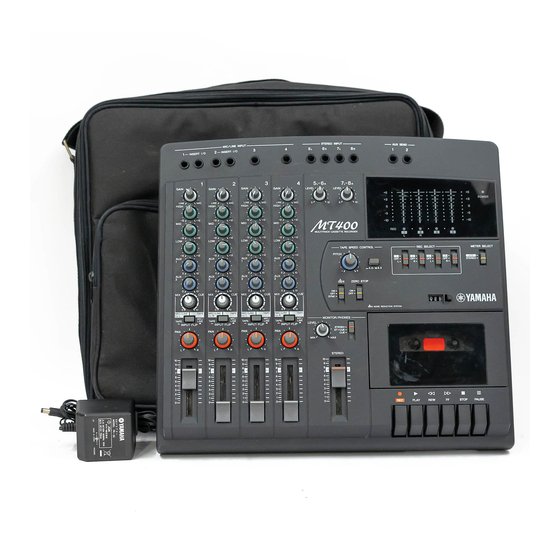
- Page 5 MT400 3 7 63 1515 0 PANEL LAYOUT Input channels GAIN GAIN control EQ control LINE HIGH AUX controls CUE control –12 INPUT-FLIP switch PAN control –12 Fader –12 MIC/LINE TAPE to L MIC/ TAPE LINE INPUT-FLIP L 13942296513...
- Page 6 MT400 3 7 63 1515 0 Recorder Section PITCH control Tape speed switch TAPE SPEED CONTROL REC SELECT METER SELECT REC SELECT switches PITCH STEREO METER SELECT switch 4.8/ dbx switch – ZERO STOP switch ZERO STOP Tape counter...
- Page 7 MT400 3 7 63 1515 0 Meter Section Level meters REC SELECT indicator POWER POWER indicator –5 –5 –10 –10 Input / Output Section STEREO INPUT L 13942296513 MIC/LINE INPUTs 1-4 INSERT I/O STEREO INPUTs AUX SEND Front Panel...
- Page 8 MT400 3 7 63 1515 0 CIRCUIT BOARD LAYOUT MIX 1/3 SUB 1/3 L 13942296513 MIX 2/3 MIX 3/3 SUB 2/3 REC 1/2 u163 REC 2/2 http://www.xiaoyu163.com...
- Page 9 MT400 3 7 6 3 1 5 1 5 0 BLOCK DIAGRAM IC101 IC103 IC104 IC106 IC107 IC108 IC109 IC110 IC201 IC110 IC303 IC105 1 3 9 4 2 2 9 6 5 1 3 IC111 w w w...
- Page 10 MT400 3 7 6 3 1 5 1 5 0 DISASSEMBLY PROCEDURE Lower Case SUB 2/3, 3/3 Circuit Boards Remove the seven (7) screws marked [320]. The Remove the lower case. (See Procedure 1.) lower case can then be removed. (Fig.1) Remove the three (3) screws marked [320d] and the two (2) screws marked [320e].
- Page 11 MT400 3 7 6 3 1 5 1 5 0 IC BLOCK DIAGRAM SUB 1/3 Circuit Board TC4069UBP IG001720 TC4066BP IX631591 NJM2068LD XM356A00 Remove the lower case. (See Procedure 1.) Hex Inverter Quad Bilateral Swich NJM4558L X614610 Remove the PITCH knob of the TAPE SPEED...
- Page 12 1 3 9 4 2 2 9 6 5 1 3 to MIX 2/3-CN112 to SUB 2/3-CN107 to MIX 2/3-CN109 to SUB 1/3-CN101 to MIX 3/3-CN110 w w w to SUB 1/3- CN102 u 1 6 3 to REC 1/2-CN504 Component side MIX : MT400-3400 http://www.xiaoyu163.com...
- Page 13 SUB-3/3 Circuit Board SUB-2/3 Circuit Board DC IN POWER SW. STEREO OUT MONITOR OUT SYNC from MIX 1/3-CN104 w w w u 1 6 3 to REC 1/2-CN506 Component side MIX : MT400-3400 Component side SUB : MT400-3600 from REC 1/2-CN507 http://www.xiaoyu163.com...
- Page 14 REC-2/2 Circuit Board PUNCH I/O PHONES 1 3 9 4 2 2 9 6 5 1 3 from REC 1/2-CN503 Component side to REC 2/2-CN508 Component side w w w u 1 6 3 from MIX 1/3-CN105 REC : MT400-3500 http://www.xiaoyu163.com...
- Page 15 MT400 3 7 63 1515 0 INSPECTIONS A. Preparation 1. Set Up Set the level controls and switches as follows (unless otherwise specified). 1-1 CH 1, 2, 3, 4 GAIN VOLUME LINE EQ/ HIGH, MID, LOW VOLUME CENTER AUX 1, 2 VOLUME...
- Page 16 MT400 3 7 63 1515 0 5. Test equipment required Low Frequency Oscillator AC voltmeter (level meter) DC voltmeter Oscilloscope Frequency Counter Mirror Cassette SONY: MC112C (TX911100) Torque meter SONY: TW-2231 (TX913450), etc. 6. Mechanical adjustment 6-1 Tape running Check that a tape curl is not created when playing the mirror tape.
- Page 17 MT400 3 7 63 1515 0 L 13942296513 u163 http://www.xiaoyu163.com...
- Page 18 MT400 3 7 63 1515 0 L 13942296513 u163 http://www.xiaoyu163.com...
-
Page 19: Troubleshooting
MT400 cannot be turned on. Make sure that a correct AC adapter is being used. Make sure that the MT400 POWER switch is set to the ON position. Make sure that the [INPUT-FLIP] switches and the monitor select switch are set to the appropriate positions. When an [INPUT-FLIP] switch is set to "MIC/LINE (... - Page 20 MT400 3 7 63 1515 0 L 13942296513 u163 http://www.xiaoyu163.com...
- Page 21 MT400 CIRCUIT DIAGRAM 1/4 ( MIX1/3 , 2/3 , 3/3 ) MT400 3 7 6 3 1 5 1 5 0 MIX3/3 MIX1/3 OPAMP OPAMP OPAMP OPAMP MIX2/3 OPAMP OPAMP OPAMP OPAMP OPAMP OPAMP OPAMP OPAMP OPAMP OPAMP OPAMP...
- Page 22 MT400 CIRCUIT DIAGRAM 2/4 ( REC1/2-1/2 ) MT400 3 7 6 3 1 5 1 5 0 to SUB1/3 CN103 REC1/2 OPAMP to MECHA HEAD HEAD SWITCH INVERTER ANALOG OPAMP SWITCH OPAMP INVERTER to MECHA HEAD HEAD SWITCH INVERTER...
- Page 23 3 7 6 3 1 5 1 5 0 MT400 CIRCUIT DIAGRAM 3/4 ( REC1/2-2/2 , REC2/2 ) MT400 REC1/2 REC2/2 INVERTER 1 3 9 4 2 2 9 6 5 1 3 INVERTER INVERTER to REC1/2-1/2 B5 OPAMP...
- Page 24 3 7 6 3 1 5 1 5 0 MT400 CIRCUIT DIAGRAM 4/4 ( SUB-1/3 , 2/3 , 3/3 ) MT400 SUB1/3 LED DRIVER LED DRIVER LED DRIVER LED DRIVER 1 3 9 4 2 2 9 6 5 1 3...
-
Page 25: Parts List
http://www.xiaoyu163.com 3 7 63 1515 0 MULTITRACK CASSETTE RECORDER PARTS LIST L 13942296513 CONTENTS OVERALL ASSEMBLY ..........2 CASSETTE MECHANISM ASSEMBLY ... 3 ELECTRICAL PARTS ..........5 Notes : DESTINATION ABBREVIATIONS : Australian model : Japanese model : British model M : South African model C : Canadian model Q : South-east Asia model... - Page 26 MT400 3 7 63 1515 0 OVERALL ASSEMBLY U110 U100 U130 U140 U160 U120 U150 L 13942296513 110 120 CN105 CN103 CN104 u163 http://www.xiaoyu163.com...
- Page 27 CX816280 Knob D.GRAY/YELLOW MT400-011-B dBx, ZERO STOP,METER SELECT CX816290 Fader Knob D.GRAY MT400-012-A CH Feder, STEREO Feder CX816300 Knob L.GRAY MT400-014-A CH Feder CX816310 Knob MT400-014-B STEREO Feder CX816320 Knob BLACK MT400-013 POWER ON/OFF AX818340 Rear Chassis MT400-100 AX818350 Holder, Jack...
- Page 28 MT400 3 7 63 1515 0 CASSETTE MECHANISM ASSEMBLY A120 A20b A20a A110 A160 A100 A150 A170 L 13942296513 A173 A130 u163 http://www.xiaoyu163.com...
- Page 29 Motor 6002 03 27 A20b NX820130 Erase Head N-E44A05 CX814531 Y Washer 9W13 00 010 CX816350 Knob MT400-004 REC,PLAY,FF, EX803191 Bind Tapping Screw-C M2X3 9P04 20 031 REW,STOP,PAUSE EX803201 Bind Tapping Screw-C M2X4 9P04 20 04 BX801160 Cassette Guide L...
- Page 30 MT400 3 7 6 3 1 5 1 5 0 ELECTRICAL PARTS PART NO. DESCRIPTION REMARKS PART NO. DESCRIPTION REMARKS REF NO. RANK REF NO. RANK ELECTRICAL PARTS MT400 C413 VF4 66600 Ceramic Capacitor UP050 10P SL J 50V...
- Page 31 MT400 3 7 63 1515 0 PART NO. DESCRIPTION REMARKS REF NO. RANK JK202 LX804910 Phone Jack YKB21-5074G Input 2 INSERT I/O JK301 LX804900 Phone Jack YKB21-5012G MIC/LINE INPUT 3 JK401 LX804900 Phone Jack YKB21-5012G MIC/LINE INPUT 4 Q101...
- Page 32 MT400 3 7 63 1515 0 PART NO. DESCRIPTION REMARKS REF NO. RANK R231 HF856820 Carbon Resistor RD16S 8.2K J 1/6W R232 HF857100 Carbon Resistor RD16S 10K J 1/6W R233 HF857390 Carbon Resistor RD16S 39K J 1/6W R241 HF855220...
- Page 33 MT400 3 7 63 1515 0 PART NO. DESCRIPTION REMARKS REF NO. RANK R519 HF858100 Carbon Resistor RD16S 100K J 1/6W R521 HF857100 Carbon Resistor RD16S 10K J 1/6W -523 HF857100 Carbon Resistor RD16S 10K J 1/6W R524 HF856330 Carbon Resistor RD16S 3.3K J 1/6W...
- Page 34 MT400 3 7 63 1515 0 PART NO. DESCRIPTION 部 品 名 REMARKS REF NO. RANK VR303 HX809250 Rotary Variable Resistor EVUF3KFK4B54 B50K HIGH CH3 VR304 HX809250 Rotary Variable Resistor EVUF3KFK4B54 B50K MID CH3 VR305 HX809200 Slide Variable Resistor...
- Page 35 MT400 3 7 63 1515 0 PART NO. DESCRIPTION 部 品 名 REMARKS REF NO. RANK C205 FX804410 Electrolytic Cap. UVR1A 220 M 10V UA654100 C206 Mylar Capacitor ECQB1H 0.01 J 50V C207 FX804380 Electrolytic Cap. UVR1H 3.3 M 50V...
- Page 36 MT400 3 7 63 1515 0 PART NO. DESCRIPTION REMARKS REF NO. RANK C334 UA654470 Mylar Capacitor ECQB1H 0.047 J 50V C335 UA653220 Mylar Capacitor ECQB1H 2200P J 50V C336 UA653100 Mylar Capacitor ECQB1H 1000P J 50V C337 FX804360 Electrolytic Cap.
- Page 37 MT400 3 7 63 1515 0 PART NO. DESCRIPTION REMARKS REF NO. RANK C516 FX804310 Electrolytic Cap. UVR1E 470 M 25V C517 V I 3 0 7 1 0 0 Ceramic Capacitor UP050 0.1 F Z 50V C518 ÅFX80432 0Ceramic Capacitor RPU07F 0.01 FZ 50...
- Page 38 MT400 3 7 63 1515 0 PART NO. DESCRIPTION REMARKS REF NO. RANK Q103 I X 8 0 8 9 0 0 Digital Transistor DTC314TS-TP Q104 I X 8 0 8 8 7 0 Digital Transistor DTC114TSA-TP Q105 I X 8 0 8 8 7 0...
- Page 39 MT400 3 7 63 1515 0 PART NO. DESCRIPTION REMARKS REF NO. RANK R131 HF856560 Carbon Resistor RD16S 5.6K J 1/6W R132 HF857120 Carbon Resistor RD16S 12K J 1/6W R133 HF857100 Carbon Resistor RD16S 10K J 1/6W R134 HF857330...
- Page 40 MT400 3 7 63 1515 0 PART NO. DESCRIPTION REMARKS REF NO. RANK R304 HF855100 Carbon Resistor RD16S 100 J 1/6W R305 HF859100 Carbon Resistor RD16S 1M J 1/6W R306 HF858100 Carbon Resistor RD16S 100K J 1/6W R307 HF858330...
- Page 41 MT400 3 7 63 1515 0 PART NO. DESCRIPTION REMARKS REF NO. RANK R430 HF858100 Carbon Resistor RD16S 100K J 1/6W R431 HF856560 Carbon Resistor RD16S 5.6K J 1/6W R432 HF857120 Carbon Resistor RD16S 12K J 1/6W R433 HF857100...
- Page 42 MT400 3 7 63 1515 0 PART NO. DESCRIPTION REMARKS REF NO. RANK -303 Connector Base Post 2P PH-B2B TP401 Connector Base Post 2P PH-B2B -403 Connector Base Post 2P PH-B2B TP501 Connector Base Post 2P PH-B2B TP601 Connector Base Post...
- Page 43 MT400 3 7 63 1515 0 PART NO. DESCRIPTION REMARKS REF NO. RANK D111 VU652800 Diode 1SR139-400(T-32) D201 VT525700 SLR-342VRTC7 CH2 Level Meter +6,+3,0 -203 VT525700 SLR-342VRTC7 D204 VT525600 SLR-342GTC7 CH2 Level Meter -5 D205 VT525600 SLR-342GTC7 CH2 Level Meter -10...
- Page 44 MT400 3 7 63 1515 0 PART NO. DESCRIPTION REMARKS REF NO. RANK SW301 KX804860 Slide Switch SSSU043-P06N1 REC SELECT 3 SW401 KX804860 Slide Switch SSSU043-P06N1 REC SELECT 4 VR101 HX809420 Rotary Variable Resistor EVJZ14F02B23 2KB PITCH VR102 HX809290...