Table of Contents
Advertisement
PK
001917
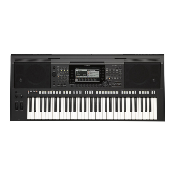
DIGITAL WORKSTATION
SERVICE MANUAL
CONTENTS
Specifications................................................................ 3
PANEL.LAYOUT................................................................... 5
CIRCUIT.BOARD.LAYOUT.&.WIRING. . ............................... 8
Disassembly.procedure. . ......................................... 12
CIRCUIT.BOARDS. . ........................................................... 21
TEST.PROGRAM. . ............................................................. 38
INITIAL.SETTING. . ............................................................. 54
PSR-S770.SYSTEM.BOOTING.FLOWCHART. . ................ 55
Psr-S970.System.booting.flowchart. . ................ 57
Psr-S770.Dmm.circuit.board.check.method.............. 59
Psr-S970.Dmh.circuit.board.check.method.............. 61
RESETTING.TO.THE.FACTORY-PROGRAMMED.SETTINGS............. 63
DATA.BACKUP................................................................... 64
VERSION.UPGRADE. . ....................................................... 65
PARTS.LIST
BLOCK.DIAGRAM
CIRCUIT.DIAGRAM
Copyright (c) Yamaha Corporation. All rights reserved. PDF
PSR-S770
PSR-S970
HAMAMATSU, JAPAN
'15.07
Advertisement
Table of Contents

Related Manuals for Yamaha PSR-S770


Summary of Contents for Yamaha PSR-S770
- Page 1 TEST.PROGRAM............... 38 INITIAL.SETTING............... 54 PSR-S770.SYSTEM.BOOTING.FLOWCHART....55 PSR-S970.SYSTEM.BOOTING.FLOWCHART....57 PSR-S770.DMM.CIRCUIT.BOARD.CHECK.METHOD....59 PSR-S970.DMH.CIRCUIT.BOARD.CHECK.METHOD....61 RESETTING.TO.THE.FACTORY-PROGRAMMED.SETTINGS..... 63 DATA.BACKUP..............64 VERSION.UPGRADE............65 PARTS.LIST BLOCK.DIAGRAM CIRCUIT.DIAGRAM 001917 HAMAMATSU, JAPAN Copyright (c) Yamaha Corporation. All rights reserved. PDF ’15.07...
-
Page 2: Specifications
This.manual.has.been.provided.for.the.use.of.authorized.Yamaha.Retailers.and.their.service.personnel..It.has.been.assumed.that.basic. service. procedures. inherent. to. the. industry,. and. more. specifically. Yamaha. Products,. are. already. known. and. understood. by. the. users,. For more information about collection and recycling of old products, please contact your local municipality, your waste disposal service or and.have.therefore.not.been.restated. - Page 3 Specifications PSR-S770/PSR-S970 ■ SPECIFICATIONS PSR-S970 PSR-S770 Product name Digital Keyboard Digital Keyboard 1,002 mm x 437 mm x 148 mm 1,002 mm x 437 mm x 148 mm Dimensions (W x D x H) (39-7/16” x 17-3/16” x 5-13/16”) (39-7/16” x 17-3/16” x 5-13/16”)
- Page 4 * The contents of this manual apply to the latest specifications as of the printing date. Since Yamaha makes continuous improvements to the product, this manual may not apply to the specifications of your particular product. To obtain the latest manual, access the Yamaha website then download the manual file. Since...
-
Page 5: Panel.layout
PSR-S770/PSR-S970 srs970_en_om.book Page 14 Friday, February 13, 2015 3:09 PM ■ PANEL LAYOUT Rear Panel • Rear Panel 12psrs970_en_om.book Page 15 Friday, February 13, 2015 3:09 PM 1 DC IN jack ............Page 16 5 [MIC/GUITAR INPUT] jack......Page 88 For connecting the power adaptor. -
Page 6: Panel Controls And Terminals
4 [MIC SETTING/VOCAL HARMONY] button (PSR-S970) / @ STYLE CONTROL buttons......Page 50 r [MIC.SETTING/VOCAL.HARMONY].button.(PSR-S970)./. !5 . [MODULATION].wheel [MIC SETTING] button (PSR-S770) .....Page 88 Controls Style playback. [MIC.SETTING].button.(PSR-S770). !6 . [PHONES].jack Calls up the display from which you can make settings for # [ASSIGN] button, LIVE CONTROL knobs.. - Page 7 PSR-S770/PSR-S970 ( [MIXER/EQ] button .........Page 95 G [MUSIC FINDER] button......... Page 80 Calls up various settings for the keyboard, Style and Song Calls up ideal panel setups for your performance. parts. H PART SELECT buttons ........Page 36 A [CHANNEL ON/OFF] button....Pages 56, 65 @4 .
- Page 8 PSR-S770/PSR-S970 ■ CIRCUIT BOARD LAYOUT & WIRING • Top view (PSR-S770) SPEAKER R (TWEETER) SPEAKER R (WOOFER) LOWER CASE ASSEMBLY SPEAKER L (WOOFER) SPEAKER L (TWEETER) • Bottom view (PSR-S770) AJACK EMKS61A UPPER CASE ASSEMBLY SHIELD COVER AJACK...
- Page 9 PSR-S770/PSR-S970 • Top view (PSR-S970) SPEAKER R (TWEETER) SPEAKER R (WOOFER) LOWER CASE ASSEMBLY SPEAKER L (WOOFER) SPEAKER L (TWEETER) • Bottom view (PSR-S970) AJACK EMKS61A UPPER CASE ASSEMBLY SHIELD COVER AJACK...
- Page 10 PSR-S770/PSR-S970 • Bottom view MK-H MK-L EMKS61A KEYBOARD ASSEMBLY • UPPER CASE ASSEMBLY KNOB • CENTER PANEL ASSEMBLY CRYSTAL DISPLAY...
- Page 11 PSR-S770/PSR-S970 ● PSR-S770 Unit Name Location Parts No. Parts Name Connection Remarks (ZP69140) Connector.Assembly.XH.S DMM.CN802.-.AJACK.CN102 6P.L=320 (ZP44110) Connector.Assembly.PH-GH.S AJACK.CN104.-.PNS.CN202 6P.L=110 (ZP44070) Connector.Assembly.PH-GH.S DMM.CN803.-.AJACK.CN100 12P.L=335 (ZP44090) Connector.Assembly.PH-GH.S DMM.CN004.-.AJACK.CN101 7P/6P.L=210 OVERALL.ASSEMBLY (ZP44100) Connector.Assembly.PH-GH.S DMM.CN003.-.EMKS61A.CN1 7P.L=180 (ZP44120) Connector.Assembly.GH.S DMM.CN002.-.PNM.CN100 10P.L=110 (ZP44170) Connector.Assembly.PH.S DMM.CN805.-.HP.CN200 7P.L=430...
-
Page 12: Disassembly.procedure
PSR-S770/PSR-S970 ■ DISASSEMBLY PROCEDURE Precautions * Disassembly or assembly should be performed on a cloth so as not to damage the LCD. * Install the filament tape and the harness clamp in the same way as they were before removal. -
Page 13: Circuit.boards
[460] on the rear and the seven (7) screws the test “068: NAND ROM Check2.” (p.48) (PSR-S970 only) marked [440A]. The DMH circuit board can then be removed. (Fig. 3) <Rear view> [440B] [460] PSR-S970 only <PSR-S970 Bottom view> [440A] [430A] AJACK [430A] [430A] UPPER CASE ASSEMBLY <PSR-S770 Bottom view> [440A] [430A] AJACK [430A] [430A] z UPPER CASE ASSEMBLY Fig. 3... - Page 14 Remove the encoder and volume knobs. (Fig. 5) 5-4. Remove the screw marked [510B]. The center panel When installing the AJACK circuit board, tighten the screws z and x shown in Fig. 3 in numerical order assembly can then be removed. (Fig. 5) and then tighten the other screws. When installing the center panel assembly, fit claws of the center panel into the holes in the upper case and install the center panel in the arrow direction. (Fig. 6) [510A] [510A] [440C] <PSR-S970 Bottom view> [430B] [430B] KEYBOARD ASSEMBLY [420B] UPPER CASE ASSEMBLY [510A] [440C] [510A] <PSR-S770 Bottom view> [430B] [420B] KEYBOARD ASSEMBLY UPPER CASE ASSEMBLY [430B] Fig. 4...
- Page 15 PSR-S770/PSR-S970 <Top view> SPEAKER GRILLE ASSEMBLY (L) VOLUME KNOB ENCORDER KNOB SPEAKER GRILLE ASSEMBLY (R) [510B] * This figure shows the PSR-S970. LIVE CONTROL KNOBS CENTER PANEL ASSEMBLY Fig. 5 CENTER PANEL ASSEMBLY CLAWS UPPER CASE ASSEMBLY Fig. 6 G CENTER PANEL ASSEMBLY...
- Page 16 PSR-S770/PSR-S970 Crystal Display PNM Circuit Board (Time required: About 7 minutes) (Time required: About 10 minutes) 6-1. Remove the lower case assembly. (See procedure 2.) 8-1. Remove the lower case assembly. (See procedure 2.) 6-2. Remove the center panel assembly. (See procedure 5.) 8-2. Remove the center panel assembly. (See procedure 5.) 6-3. Remove the two (2) screws marked [300A]. The LCD 8-3. Remove the LCD fixture L. (See procedure 6-3.) fixture L can then be removed. (Fig. 7) 8-4. Remove the LCD fixture R. (See procedure 6-4.) 6-4. Remove the two (2) screws marked [300B]. The LCD 8-5. Remove the twenty-six (26) screws marked [300D]. fixture R can then be removed. (Fig. 7) The PNM circuit board can then be removed. (Fig. 8) When installing the LCD fixture L and R, tighten When installing the PNM circuit board, apply the PNM screws while pushing it in the arrow direction.
- Page 17 PSR-S770/PSR-S970 Wheel, MOD Circuit Board PNC Circuit Board (Time required: About 4 minutes) (Time required: About 5 minutes) 12-1. Remove the lower case assembly. (See procedure 2.) 14-1. Remove the lower case assembly. (See procedure 2.) 12-2. Remove the two (2) screws marked [500B]. The MOD 14-2. Remove the keyboard assembly. (See procedure 10.) circuit board can then be removed with the wheel. 14-3. Remove the ten (10) screws marked [500D]. The PNC (Fig. 9) circuit board can then be removed. (Fig. 9) The wheel is not part of the MOD circuit board. When When installing the PNC circuit board, tighten the replacing the MOD circuit board, remove the wheel screws z and x shown in Fig. 9 in numerical order...
- Page 18 (Time required: About 4 minutes) be bent in the counterclockwise direction. 18-1. Remove the lower case assembly. (See procedure 2.) 18-2. Remove the four (4) screws marked [200]. The woofer can then be removed. (Fig. 10) The left and right woofers can be removed in the same method. • Top view * This figure shows the PSR-S770. LOWER CASE ASSEMBLY [200] [200] [210] [210] SPEAKER R (TWEETER) SPEAKER L (TWEETER)
- Page 19 PSR-S770/PSR-S970 Disassembling the Keyboard Assembly 20-6. Rubber Contact 20-6-1. R emove the rubber contact. (Fig. 12) (Photo 2) 20-1. Remove the lower case assembly. (See procedure 2.) 20-2. Remove the keyboard assembly. (See procedure 10.) 20-7. White and Black Keys 20-8. Remove the twenty-one (21) screws marked [140K], 20-3. EMKS61A Circuit Board then remove the black keys from the lower notes. (Time required: About 5 minutes) (Fig. 13) 20-3-1. Remove the two (2) screws marked [30]. The 20-8-1. Remove the white keys DFA and C’. (Fig. 13)
- Page 20 PSR-S770/PSR-S970 Assembling the Keyboard Assembly 21-4. Install the rubber contacts while pulling the keys up. (Fig. 14, Fig. 15) 21-1. Install the white keys CEGB from the lower notes. When fitting the rubber contacts, raise both ends (Fig. 13) of the frame so that keys do not push the rubber 21-2. Install the white keys DFA and C’. (Fig. 13) contact up. 21-3. Install the black keys from the higher notes, and 21-5. Install the MK-L and MK-H circuit boards in the...
- Page 21 PSR-S770/PSR-S970 ■ ■ CIRCUIT■BOARDS AJACK■Circuit■Board■(YG589F0)............26/27 DMM■Circuit■Board■(YG546C0).(PSR-S770)........22/23 DMH■Circuit■Board■(YG545C0).(PSR-S970)........24/25 EMKS61A■Circuit■Board■(X6637C0)............ 36/37 KNOB■Circuit■Board■(YG581D0)............30/31 HP■Circuit■Board■(YG589F0)..............35 MK-H■Circuit■Board■(XR565C0)..............37 MK-L■Circuit■Board■(XR564C0)..............36 MOD■Circuit■Board■(YG589F0)..............35 PB■Circuit■Board■(YG589F0)..............35 PNC■Circuit■Board■(YG588D0)..............32 PNL■Circuit■Board■(YG588D0)..............33 PNM■Circuit■Board■(YG581D0)............. 28/29 PNR■Circuit■Board■(YG588D0)..............34 PNS■Circuit■Board■(YG581D0)............. 30/31...
- Page 22 PSR-S770/PSR-S970 ■DMM■Circuit■Board■(PSR-S770) to SP Rch (Wo, Tw) to SP Lch (Wo, Tw) to AJACK-CN100 to HP-CN200 The Backup ROM, IC010, cannot be replaced individually with new one because the IC010 has a Component■side “Hardware ID” which is exclusive or unique to each DMM circuit board. A Hardware ID cannot be exported or imported due to Copy protection.
- Page 23 PSR-S770/PSR-S970 ■DMM■Circuit■Board■(PSR-S770) Pattern■side 2NA-ZN12380.
- Page 24 PSR-S770/PSR-S970 ■DMH■Circuit■Board■(PSR-S970) Scale:.90/100 to SP Rch (Wo, Tw) to SP Lch (Wo, Tw) to AJACK-CN100 to HP-CN200 Component■side * The Backup ROM, IC010, cannot be replaced individually with new one because the IC010 has a “Hardware ID” which is exclusive or unique to each DMH circuit board. A Hardware ID cannot be exported or imported due to Copy protection.
- Page 25 PSR-S770/PSR-S970 ■DMH■Circuit■Board■(PSR-S970) Scale:.90/100 Pattern■side 2NA-ZN12370.
- Page 26 PSR-S770/PSR-S970 ■AJACK■Circuit■Board Scale:.90/100 to DMH-CN802 (PSR-S970) to DMM-CN802 (PSR-S770) Component■side 2NA-ZN43330.
- Page 27 PSR-S770/PSR-S970 ■AJACK■Circuit■Board Scale:.90/100 Pattern■side 2NA-ZN43330.
- Page 28 PSR-S770/PSR-S970 ■PNM■Circuit■Board Scale:.70/100 Component■side to PNL-CN102 to KNOB-CN400 to DMH-CN002 (PSR-S970) to DMM-CN002 (PSR-S770) 2NA-ZN43310.
- Page 29 PSR-S770/PSR-S970 ■PNM■Circuit■Board Scale:.70/100 Pattern■side 2NA-ZN43310.
- Page 30 PSR-S770/PSR-S970 ■PNS■Circuit■Board to PNR-CN300 to PNC-CN200 Component■side ■KNOB■Circuit■Board to PNM-CN402 Component■side 2NA-ZN43310.
- Page 31 PSR-S770/PSR-S970 ■PNS■Circuit■Board Pattern■side ■KNOB■Circuit■Board Pattern■side 2NA-ZN43310.
- Page 32 PSR-S770/PSR-S970 ■PNC■Circuit■Board Scale:.75/100 Component■side Pattern■side 2NA-ZN43320...
- Page 33 PSR-S770/PSR-S970 ■PNL■Circuit■Board Scale:.75/100 Component■side Pattern■side 2NA-ZN43320...
- Page 34 PSR-S770/PSR-S970 ■PNR■Circuit■Board Scale:.90/100 Component■side Pattern■side 2NA-ZN43320...
- Page 35 PSR-S770/PSR-S970 ■HP■Circuit■Board Component■side Pattern■side ■MOD■Circuit■Board to PNL-CN101 Component■side Pattern■side ■PB■Circuit■Board to PNL-CN101 Component■side Pattern■side 2NA-ZN43330.
- Page 36 PSR-S770/PSR-S970 ■MK-L■Circuit■Board Scale:.90/100 to MK-H I’ I’ J’ J’ Component■side ■EMKS61A■Circuit■Board to MK-H Component■side to DMM-CN003 (PSR-S770) EMKS61A:. 2NA-WF31010 to DMH-CN003 (PSR-S970) MK-L:. 2NA-VV58380...
- Page 37 PSR-S770/PSR-S970 ■MK-H■Circuit■Board Scale:.90/100 to EMKS61A-CN3 K’ L’ K’ to MK-L L’ Component■side ■EMKS61A■Circuit■Board Pattern■side EMKS61A:. 2NA-WF31010 MK-H:. 2NA-VV58390...
- Page 38 PSR-S770/PSR-S970 ■ ■ TEST■PROGRAM * If you execute Test No. 81 Factory Set, the setting data and user data will be lost. Be sure to save these data for backup in advance. (See page 64.) 1.■ Measurement■condition 1-1.■ Environment Perform tests under following conditions. Ordinary temperature (5°C to 40°C) Ordinary humidity (20% to 90%) If the test results deviate from the test standard range, however, re-test under such conditions as the ordinary temperature (5°C to 40°C) and ordinary humidity (30% to 90% relative humidity).
- Page 39 PSR-S770/PSR-S970 2.■ Test■mode 2-1.■ Starting■Up■Test■mode There are two methods to start up the Test mode. Method■1 While pressing keys [C#2], [F2], [G#2] (C#2 major chord) simultaneously, turn on the [ ] (Standby/On) switch. When Test mode started successfully, “TEST” is shown on the LCD.
- Page 40 PSR-S770/PSR-S970 3.■ Test■program■list LCD■display Test■items■and■judging■conditions 001■:■Version Indicates the model name, designated country information and each ROM version (*.**). 1) Press the [START/STOP] button, and the versions are shown on the LCD. PSR-S770 Model■Name■ :■PSR-S770■(E) Main■Prog■ROM■ :■*.** Wave■Data■ROM■ :■*.** Hardware■ID■ :■***********...
- Page 41 PSR-S770/PSR-S970 LCD■display Test■items■and■judging■conditions 004 : NAND ROM Check1 Executes the simplified check of the NAND ROM connected to the CPU bus. (PSR-S970 only) 1) Press the [START/STOP] button to start the test. OK: OK NG:■NAND■ROM■(IC ) NG *** 2) Confirm that “OK” is shown on the LCD.
- Page 42 5) Press the [START/STOP] button to stop the sound and to exit the TEST item. 017 : EQ Low Check Checks the low-frequency sound. (PSR-S770 only) 1) Press the [START/STOP] button to produce the C1 sine wave sound. 2) Press the [START/STOP] button to stop the sound and to exit the TEST item.
- Page 43 PSR-S770/PSR-S970 LCD■display Test■items■and■judging■conditions 023■:■DAC■MUTE■Check Checks whether the DAC MUTE for the DAC IC’s output works properly or not. 1) Press the [START/STOP] button to produce the C5 sine wave sound. “OFF” is shown on the LCD. 2) Press the TAB [>] button to activate the DAC MUTE circuit.
- Page 44 PSR-S770/PSR-S970 LCD■display Test■items■and■judging■conditions 026 : SIOF Check Checks whether the two SIOF circuits, which are defined Line-A and Line-B in this test, are connected properly. Also, checks whether the control ports of AUDIO clock are connected properly. 1) Press the [START/STOP] button to start the test of Line-A and AUDIO-clock ports.
- Page 45 PSR-S770/PSR-S970 LCD■display Test■items■and■judging■conditions 032■:■All■LED■On■ Checks whether all the LED lamps light properly or not. 1) Press the [START/STOP] button to start the test. All the LED lamps are turned on, and “-■-” is shown on the LCD. 2) Confirm that all the LED lamps light.
- Page 46 PSR-S770/PSR-S970 LCD■display Test■items■and■judging■conditions 044■:■Pitch■Bend■Wheel■ Checks whether the PITCH BEND wheel control works properly or not. Check 1) Press the [START/STOP] button. “Pitch■Bend■Up■128” is shown on the LCD. 2) Roll the [Pitch Bend] wheel upward to the maximum position to produce the G3 beep.
- Page 47 PSR-S770/PSR-S970 LCD■display Test■items■and■judging■conditions 054■:■Pedal2■Check Checks whether the Foot Pedal plugged into FOOT PEDAL2 jack works properly or not. 1) Connect the foot pedal (FC7) to FOOT PEDAL 2 jack. 2) Press the [START/STOP] button to start the test. “Pedal2■Down” is shown on the LCD.
- Page 48 PSR-S770/PSR-S970 LCD■display Test■items■and■judging■conditions 068 : NAND ROM Check2 Executes the complete check of the NAND ROM. (It will take about 5 minutes.) (PSR-S970 only) 1) Press the [START/STOP] button to start the test. OK: OK NG:■NAND■ROM■(IC ) NG■ *** 2) Confirm that “OK” is shown on the LCD.
- Page 49 After restarting, the instrument return to the play mode and the main screen appears. NOTE: Never turn off the power until the Main display appears. Doing so may cause a malfunction. (It will take about 20 seconds.) 083■:■Test■Exit Let’s you exit from the Test mode to the normal mode. 1) Press the [START/STOP] button. The Test mode will end, then the PSR-S770/PSR-S970 will be restarted. NOTE: Never turn off the power until the Main display appears. Doing so may cause a malfunction.
- Page 50 PSR-S770/PSR-S970 4.■ Other■Inspections 4-1.■ AUX■IN Take measurement with the Test Program [028: AUX-IN Check] selected. Check that each terminal output is as shown in the table below when a signal is inputted into AUX IN. PHONES■(33■W■load) OUTPUT ■ INPUT AUX IN L: Sine wave (1 kHz, 0 dBu) +1.6 ±...
- Page 51 PSR-S770/PSR-S970 ● ● Switch■Test■Sequence Turn SW■Name/Display LED■made■to■turn■on Note■No. Turn SW■Name/Display LED■made■to■turn■on Note■No. SELECT TAB < SCORE TAB > LYRICS/TEXT GUIDE GUIDE REPEAT REPEAT EXTRA TR EXTRA TR (RED, GREEN) TR 2 TR2 LEFT (RED, GREEN) TR 1 TR1 RIGHT (RED, GREEN)
- Page 52 PSR-S770/PSR-S970 ● ● Panel■PCB■division■check■1■■ (PNC,■PNL■and■PNR■circuit■boards) Turn SW■Name/Display LED■made■to■turn■on Note■No. 125 REGIST. MEMORY 3 REGIST. MEMORY 3 (RED, GREEN) Turn SW■Name/Display LED■made■to■turn■on Note■No. 126 REGIST. MEMORY 4 REGIST. MEMORY 4 (RED, GREEN) REGIST. MEMORY 8 REGIST. MEMORY 8 (RED, GREEN) 127 REGIST. MEMORY 5 REGIST.
- Page 53 PSR-S770/PSR-S970 ● ● Panel■PCB■division■check■2■■ (PNM■and■PNS■circuit■boards) Turn SW■Name/Display LED■made■to■turn■on Note■No. Turn SW■Name/Display LED■made■to■turn■on Note■No. SELECT SCORE LYRICS/TEXT EXIT GUIDE GUIDE TAB < REPEAT REPEAT TAB > EXTRA TR EXTRA TR (RED, GREEN) TR 2 TR2 LEFT (RED, GREEN) TR 1 TR1 RIGHT (RED, GREEN)
- Page 54 PSR-S770/PSR-S970 ■ ■ INITIAL■SETTING • [MASTER VOLUME] dial: MIN • LIVE CONTROL 1, 2 knobs: CENTER • [MODULATION] wheel: • [GAIN]: • [MIC/GUITAR]:...
- Page 55 PSR-S770/PSR-S970 ■ ■ PSR-S770■SYSTEM■BOOTING■FLOWCHART If accessing Program Flash Power ON doesn’t start, SH7731 Initializing SH7731 port. (IC001) may be faulty. BL-ON = L (CN401, 3) BL-PWM =L (CN401, 4) BL_POW_EN = L (IC412, 4) Accessing Program Setting CPU registers. PSWO = H (IC013, 2) Flash (IC008) starts.
- Page 56 PSR-S770/PSR-S970 Access to SDRAM (IC207), SWP-NAND (IC600, IC601) and SWP-SDRAM (IC602) Has Factory Set started. been executed? (Data transferred from SWP NAND to SWP SDRAM and further to CPU SDRAM) When the owner name has been registered. For example, power Owner name displayed.
- Page 57 PSR-S770/PSR-S970 ■ ■ PSR-S970■SYSTEM■BOOTING■FLOWCHART If accessing Program Flash Power ON doesn’t start, SH7731 Initializing SH7731 port. (IC001) may be faulty. BL-ON = L (CN401, 3) BL-PWM =L (CN401, 4) BL_POW_EN = L (IC412, 4) Accessing Program Setting CPU registers. PSWO = H (IC013, 2) Flash (IC008) starts.
- Page 58 PSR-S770/PSR-S970 Access to NAND FLASH (IC202, 203) and SDRAM (IC207) started. Has Factory Set (Data transferred from CPU NAND to been executed? SDRAM) When the owner name has been registered. For example, power Owner name displayed. switch turned off while writing.
- Page 59 PSR-S770/PSR-S970 ■ ■ PSR-S770■DMM■CIRCUIT■BOARD■CHECK■METHOD The DMM Circuit Board is provided with test points for service check purposes. Check the test points on the DMM Circuit Board if the following symptoms appear. Symptoms and check items (1) No LCD display with Power SW ON --> Check items ① to ⑦ sequentially.
- Page 60 PSR-S770/PSR-S970 DMM■Circuit■Board■(ZN123800) Component side...
- Page 61 PSR-S770/PSR-S970 ■ ■ PSR-S970■DMH■CIRCUIT■BOARD■CHECK■METHOD The DMH Circuit Board is provided with test points for service check purposes. Check the test points on the DMH Circuit Board if the following symptoms appear. Symptoms and check items (1) No LCD display with Power SW ON --> Check items ① to ⑦ sequentially.
- Page 62 PSR-S770/PSR-S970 DMH■Circuit■Board■(ZN123700) Component side...
-
Page 63: Resetting.to.the.factory-Programmed.settings
3. Press the [8 ] (OK) button to apply the selected icon. [8 ] (CANCEL) button. PSR-S770/PSR-S970 ■ ■ RESETTING■TO■THE■FACTORY-PROGRAMMED■SETTINGS Resetting to the Factory-programmed Settings While holding the right-most key (C6) on the keyboard, turn the power on. This resets the settings of the entire instrument (referred to as the System Setup parameters) to their factory default settings. -
Page 64: Data.backup
PSR-S770/PSR-S970 ■ ■ DATA■BACKUP Data Backup You can back up all data saved in the USER drive (except Protected Songs and Expansion Voices/Styles) and all settings of the instrument to a USB flash drive as a single file. Connect a USB flash drive to the [USB TO DEVICE] terminal for NOTE the backup destination. -
Page 65: Version.upgrade
PSR-S770/PSR-S970 ■ ■ VERSION■UPGRADE Download the version upgrade program from the Yamaha official website. List■of■the■updating■Flash■ROM ■ ● Main Program IC008 PSR-S770 Wave Data IC600, IC601 Main Program IC008 PSR-S970 NAND Data IC202, IC203 Wave Data IC600, IC601 File■name ■ ●... - Page 66 PSR-S770/PSR-S970 * Follow the display on the LCD for this operation. ■ Press the [START/STOP] button to start the installations. ■ Press the [START/STOP] button again. ■ A progress bar for installation will appear. ■ When the installation is complete, the following message appears with a new firmware version.
-
Page 67: Parts List
DIGITAL WORKSTATION PARTS LIST CONTENTS PSR-S770 OVERALL ASSEMBLY ........2 PSR-S970 OVERALL ASSEMBLY ........4 UPPER CASE ASSEMBLY ..........6 CENTER PANEL ASSEMBLY .......... 9 LOWER CASE ASSEMBLY ..........12 KEYBOARD ASSEMBLY ..........14 PSR-S770 ELECTRICAL PARTS ......15–19 PSR-S970 ELECTRICAL PARTS ......20–24... - Page 68 PSR-S770/PSR-S970 ■ PSR-S770 OVERALL ASSEMBLY Upper case assembly : See page 6. Keyboard assembly : See page 14. Lower case assembly : See page 12.
- Page 69 PART NO. DESCRIPTION 部 品 名 REMARKS REF NO. OVERALL ASSEMBLY 総 組 立 PSR-S770 OVERALL ASSEMBLY 総 組 立 (ZP45870) UPPER CASE ASSEMBLY 上 ケ ー ス A s s ’ y (ZP36040) LOWER CASE ASSEMBLY 下 ケ ー ス A s s ’ y...
- Page 70 PSR-S770/PSR-S970 ■ PSR-S970 OVERALL ASSEMBLY Upper case assembly : See page 6. Keyboard assembly : See page 14. Lower case assembly : See page 12.
- Page 71 PSR-S770/PSR-S970 PART NO. DESCRIPTION 部 品 名 REMARKS REF NO. OVERALL ASSEMBLY 総 組 立 PSR-S970 OVERALL ASSEMBLY 総 組 立 (ZP34940) UPPER CASE ASSEMBLY 上 ケ ー ス A s s ’ y (ZP35000) LOWER CASE ASSEMBLY 下 ケ ー ス A s s ’ y...
- Page 72 PSR-S770/PSR-S970 ■ UPPER CASE ASSEMBLY 20 Center panel assembly :See page 9. Upper case sub assembly 300b 300a Wheel assembly...
- Page 73 品 名 REMARKS REF NO. UPPER CASE ASSEMBLY 上 ケ ー ス A s s ’ y PSR-S770 UPPER CASE ASSEMBLY 上 ケ ー ス A s s ’ y (ZP36040) ZP361100 UPPER CASE SUB ASSEMBLY 上 ケ ー ス サ ブ A s s ’ y...
- Page 74 PSR-S770/PSR-S970 PSR-S970 ● PART NO. DESCRIPTION 部 品 名 REMARKS REF NO. UPPER CASE ASSEMBLY 上 ケ ー ス A s s ’ y PSR-S970 UPPER CASE ASSEMBLY 上 ケ ー ス A s s ’ y (ZP35000) ZP350400 UPPER CASE SUB ASSEMBLY 上...
- Page 75 PSR-S770/PSR-S970 ■ CENTER PANEL ASSEMBLY Center panel sub assembly...
- Page 76 品 名 REMARKS REF NO. CENTER PANEL ASSEMBLY C パ ネ ル A s s ’ y PSR-S770 CENTER PANEL ASSEMBLY C パ ネ ル A s s ’ y (ZP36170) ZP361800 CENTER PANEL SUB ASSEMBLY C パ ネ ル サ ブ A s s ’ y...
- Page 77 PSR-S770/PSR-S970 PSR-S970 ● PART NO. DESCRIPTION 部 品 名 REMARKS REF NO. CENTER PANEL ASSEMBLY C パ ネ ル A s s ’ y PSR-S970 CENTER PANEL ASSEMBLY C パ ネ ル A s s ’ y (ZP35080) ZP350900 CENTER PANEL SUB ASSEMBLY C...
- Page 78 PSR-S770/PSR-S970 ■ LOWER CASE ASSEMBLY PSR-S770 PSR-S770 Lower case sub assembly * This figure shows the PSR-S970.
- Page 79 品 名 REMARKS REF NO. LOWER CASE ASSEMBLY 下 ケ ー ス A s s ’ y PSR-S770 LOWER CASE ASSEMBLY 下 ケ ー ス A s s ’ y (ZP54100) WZ899400 LOWER CASE SUB ASSEMBLY 下 ケ ー ス サ ブ A s s ’ y...
- Page 80 品 名 REMARKS REF NO. KEYBOARD ASSEMBLY 1 6 M 鍵 盤 E M K S A PSR-S770/PSR-S970 WB91420R KEYBOARD ASSEMBLY 16M C61-2M-EBUS 1 6 M 鍵 盤 E M K S A WF266600 BIND HEAD TAPPING SCREW-P 3.0X8 MFZN2B3 P...
- Page 81 PSR-S770/PSR-S970 ■ PSR-S770 ELECTRICAL PARTS AJACK/HP/MOD/PB PART NO. DESCRIPTION 部 品 名 REMARKS REF NO. ELECTRICAL PARTS 電 気 部 品 PSR-S770 ZP451400 CIRCUIT BOARD AJACK A J A C K シ ー ト (ZN43330)(YG589F0) ZP451500 CIRCUIT BOARD H P...
- Page 82 PSR-S770/PSR-S970 AJACK/HP/MOD/PB and DMM PART NO. DESCRIPTION 部 品 名 REMARKS REF NO. C430 UN866470 ELECTROLYTIC CAPACITOR BP 4.70 50.0V RX TP B P ケ ミ コ ン C432 UR867100 ELECTROLYTIC CAPACITOR 10.00 50.0V RX TP ケ ミ コ ン...
- Page 83 PSR-S770/PSR-S970 DMM and EMKS61A and KNOB/PNM/PNS PART NO. DESCRIPTION 部 品 名 REMARKS REF NO. IC008 YG840B00 IC S29GL512S10TFI020 I C NOR FLASH ROM 512M MAIN PROGRAM IC010 S29GL128S90TFI020 I C NOR FLASH ROM 128M BACKUP (YA121B0) IC018 YG621A00 IC MB88155PFT-G-112 I...
- Page 84 PSR-S770/PSR-S970 KNOB/PNM/PNS and MK-H and MK-L and PNC/PNL/PNR PART NO. DESCRIPTION 部 品 名 REMARKS REF NO. LD119 WJ491700 LED (CHIP) AMBER BL-HJF36J-TRB チ ッ プ L E D WORLD LD120 WJ491700 LED (CHIP) AMBER BL-HJF36J-TRB チ ッ プ L...
- Page 85 PSR-S770/PSR-S970 PNC/PNL/PNR PART NO. DESCRIPTION 部 品 名 REMARKS REF NO. ZP450900 CIRCUIT BOARD P N R シ ー ト (ZN43320)(YG588D0) LD100 WJ491700 LED (CHIP) AMBER BL-HJF36J-TRB チ ッ プ L E D ACMP LD101 WJ491600 LED (CHIP) AMBER/Y.GREEN BL-HJFGE36J-TRB チ...
- Page 86 PSR-S770/PSR-S970 ■ PSR-S970 ELECTRICAL PARTS AJACK/HP/MOD/PB PART NO. DESCRIPTION 部 品 名 REMARKS REF NO. ELECTRICAL PARTS 電 気 部 品 PSR-S970 ZP451400 CIRCUIT BOARD AJACK A J A C K シ ー ト (ZN43330)(YG589F0) ZP451500 CIRCUIT BOARD H P...
- Page 87 PSR-S770/PSR-S970 AJACK/HP/MOD/PB and DMH PART NO. DESCRIPTION 部 品 名 REMARKS REF NO. C430 UN866470 ELECTROLYTIC CAPACITOR BP 4.70 50.0V RX TP B P ケ ミ コ ン C432 UR867100 ELECTROLYTIC CAPACITOR 10.00 50.0V RX TP ケ ミ コ ン...
- Page 88 PSR-S770/PSR-S970 DMH and EMKS61A and KNOB/PNM/PNS PART NO. DESCRIPTION 部 品 名 REMARKS REF NO. IC002 YMW832-CZ I C SWP70 (YF447B0) IC004 X7701A00 IC BU4229G-TR I C SYSTEM RESET IC007 YC019A00 IC S-80944CNNB-G9ET2G I C SYSTEM RESET IC008 YG830C00 IC S29GL512S10TFI020 I...
- Page 89 PSR-S770/PSR-S970 KNOB/PNM/PNS PART NO. DESCRIPTION 部 品 名 REMARKS REF NO. LD104 WJ491700 LED (CHIP) AMBER BL-HJF36J-TRB チ ッ プ L E D BALLAD LD105 WJ491600 LED (CHIP) AMBER/Y.GREEN BL-HJFGE36J-TRB チ ッ プ 2 色 L E D MIC SETTING/VOCAL HARMONY...
- Page 90 PSR-S770/PSR-S970 KNOB/PNM/PNS and MK-H and MK-L and PNC/PNL/PNR PART NO. DESCRIPTION 部 品 名 REMARKS REF NO. R105 RD15518R CARBON RESISTOR (CHIP) 180.0 1/4 J TP チ ッ プ 抵 抗 R200 RD155120 CARBON RESISTOR (CHIP) 120.0 1/4 J TP チ...
-
Page 91: Circuit Diagram
DIGITAL WORKSTATION CIRCUIT DIAGRAM ■ ■ CONTENTS PSR-S770 BLOCK DIAGRAM ..............3 PSR-S970 BLOCK DIAGRAM ..............4 CIRCUIT DIAGRAM DMM (001–005) (PSR-S770) ............5–9 DMH (001–005) (PSR-S970) ............10–14 AJACK (AJACK, HP, MOD, PB) ............15 PN1 001 (PNM) .................. 16 PN1 002 (PNS) ................... - Page 92 PSR-S770/PSR-S970 Notation for Circuit Diagrams 1. How to identify inter-sheet connectors USB-IC 003:L8 This indicates the location of the counter inter-sheet connector. (The alphabet indicates horizontal direction and the number indicates vertical direction.) Signal name The 1-digit number indicates the destination page.
- Page 93 ■ PSR-S770 BLOCK DIAGRAM PSR-S770/PSR-S970 MAIN CPU address map Master Volume TR200–204 SW/LED SW101–159 FT200–204 /CS0 PRG-/CS SW/LED VR100 Matrix LD100–120 Matrix PORT /CS1 SW200–239 E_PNS3 PEDAL1-/IN LD200–228 IC200 (80P) /CS2 SDRAM-/CS PEDAL2-/IN Internal TR100–102, TR303 10MHz DRIVER /CS3 SDRAM-/CS Oscillator PEDAL1 FT100–104...
- Page 94 ■ PSR-S970 BLOCK DIAGRAM PSR-S770/PSR-S970 MAIN CPU address map Master Volume TR200–204 SW/LED SW101–159 FT200–204 /CS0 PRG-/CS SW/LED VR100 Matrix LD100–120 Matrix PORT /CS1 SW200–239 E_PNS3 PEDAL1-/IN LD200–228 IC200 (80P) /CS2 SDRAM-/CS PEDAL2-/IN Internal TR100–102, TR303 10MHz DRIVER /CS3 SDRAM-/CS Oscillator PEDAL1 FT100–104...
- Page 95 ■ DMM 001 CIRCUIT DIAGRM (PSR-S770) PSR-S770/PSR-S970 SWP70 MAIN CPU IC002 NOR FLASH ROM 512M NOR FLASH ROM 128M YMW832-CZ A[1] IC001 A[1] 3:R9 A[2] R8A77310D333BG A[2] 3:R9 BOOT/PROGRAM BACKUP A[1] R116 A[3] B1 CA0 A[3] 3:R9 A[2] A[4] C2 CA1 A[4] 3:R9 AC11...
- Page 96 ■ DMM 002 CIRCUIT DIAGRM (PSR-S770) PSR-S770/PSR-S970 MAIN CPU IC001 R8A77310D333BG SDR-SDRAM 256M SDR-SDRAM 128M SDR-SDRAM 256M HPD63/PTN7 +3.3SH EM203 HPD62/PTN6 NFM21PC105B1A3D WORK WORK WORK HPD61/PTN5 HPD60/PTN4 HPD59/PTN3 HPD58/PTN2 HPD57/PTN1 C236 CS3(x32)-LH C294 CS2(x16)-LL C308 CS3(x32)-LL HPD56/PTN0 DGND HPD55/PTB7 IC206 IC207 IC208 HPD54/PTB6 W9825G6JH-6...
- Page 97 ■ DMM 003 CIRCUIT DIAGRM (PSR-S770) PSR-S770/PSR-S970 MAIN CPU +3.3D R435 R436 R432 2.2K 1/16W XTALUSB R474 R476 EXTALUSB R433 to LCD R434 5.6K VBUS +3.3D To Host (Full Speed) REFRIN JC0.5 not installed +3.3D AG33 C425 C429 AV33 0.1u DGND DGND R481 0...
- Page 98 ■ DMM 004 CIRCUIT DIAGRM (PSR-S770) PSR-S770/PSR-S970 NAND FLASH ROM 2G NAND FLASH ROM 2G WAVE-L WAVE-H +3.3TG +3.3TG C703 C702 IC600 IC601 S34ML04G100TFI000 S34ML04G100TFI000 1 NC 1 NC DGND DGND 2 NC 2 NC 3 NC 3 NC DGND DGND 4 NC 4 NC...
- Page 99 ■ DMM 005 CIRCUIT DIAGRM (PSR-S770) PSR-S770/PSR-S970 +12A IC804 NE5532DR OP AMP IC812 +3.3TG C915 PCM1803ADBR 4 V- 0.1u MODE1 VINL MODE0 VINR IC804 AGND C875 NE5532DR IC804 FMT1 VREF1 R868 NE5532DR 1/50 C902 FMT0 VREF2 R873 R882 R885 R912 MICIN 1/16W 1.5K 100P L814 0.5%...
- Page 100 ■ DMH 001 CIRCUIT DIAGRM (PSR-S970) PSR-S770/PSR-S970 SWP70 MAIN CPU IC002 NOR FLASH ROM 512M NOR FLASH ROM 128M YMW832-CZ A[1] IC001 A[1] 3:R9 A[2] R8A77310D333BG A[2] 3:R9 A[1] R116 A[3] B1 CA0 A[3] 3:R9 BOOT/PROGRAM BACKUP A[2] A[4] C2 CA1 A[4] 3:R9 AC11...
- Page 101 ■ DMH 002 CIRCUIT DIAGRM (PSR-S970) PSR-S770/PSR-S970 MAIN CPU IC001 SDR-SDRAM 128M SDR-SDRAM 128M SDR-SDRAM 256M SDR-SDRAM 128M SDR-SDRAM 128M R8A77310D333BG RD[63] WORK WORK WORK WORK WORK HPD63/PTN7 RA201 RD[62] +3.3SH +3.3SH HPD62/PTN6 EM203 EM202 47*4 RD[61] NFM21PC105B1A3D NFM21PC105B1A3D HPD61/PTN5 RD[60] HPD60/PTN4 RD[59] HPD59/PTN3...
- Page 102 ■ DMH 003 CIRCUIT DIAGRM (PSR-S970) PSR-S770/PSR-S970 MAIN CPU +3.3D R435 R436 2.2K R432 XTALUSB R474 R476 EXTALUSB R433 to LCD R434 5.6K VBUS +3.3D To Host (Full Speed) REFRIN not installed JC0.5 +3.3D AG33 C425 C429 AV33 To LCD UNIT C401 0.1u DGND...
- Page 103 ■ DMH 004 CIRCUIT DIAGRM (PSR-S970) PSR-S770/PSR-S970 NAND FLASH ROM 8G NAND FLASH ROM 8G WAVE-L WAVE-H +3.3TG +3.3TG C703 C702 IC600 IC601 S34ML08G101TFI000 S34ML08G101TFI000 1 NC 1 NC DGND DGND 2 NC 2 NC 3 NC 3 NC DGND DGND 4 NC 4 NC...
- Page 104 ■ DMH 005 CIRCUIT DIAGRM (PSR-S970) PSR-S770/PSR-S970 +3.3TG OP AMP IC809 IC804 NE5532DR IC804 AK5357ET-E2 C875 R868 NE5532DR 1/50 1.5K C902 R873 R885 R912 MICIN BK1005HM601-T CKS0 AINR R882 100P 1/16W L814 CKS2 AINL 0.5% SWP70 CKS1 1:G13;O4;O7 DAC-IC VCOM +12A SCLK AGND C866 0.1u...
- Page 105 ■ AJACK CIRCUIT DIAGRAM (PSR-S770/PSR-S970) PSR-S770/PSR-S970 +12M GAIN:0 ~ +33.5dB C200 not installed GUITAR LPF:fc=43kHz(GAIN MAX) 220/25 SSSF121900 AJACK NE5532DR J202 not installed 6.0mm SW400 C201 JK200 OP AMP CN200 220/25 R155 IC403 MSJ-064-15A_B_AG PH7P L116 SBT-0210T to DMM-CN805 (PSR-S770) C443 HP-L J201...
- Page 106 ■ PN1 001 (PNM) CIRCUIT DIAGRAM (PSR-S770/PSR-S970) PSR-S770/PSR-S970 to KNOB-CN400 <Page 18: B-3> not installed GUIDE SELECT SCORE LYRICS/TEXT SW135 SW111 SW120 SW125 S[15] S[16] S[15] S[15] CN100 S[15] BM10B-GHS-TBT D116 D125 D135 KDS4148U-RTK/P KDS4148U-RTK/P KDS4148U-RTK/P E-IC E-IC KDS4148U-RTK/P to DMM-CN002 (PSR-S770) L101 S[0] D143...
- Page 107 ■ PN1 002 (PNS) CIRCUIT DIAGRAM (PSR-S770/PSR-S970) PSR-S770/PSR-S970 S[2] C226 100/16 not installed C250 100/16 C251 100/16 D[2] C209 0.1u D[3] R200 L[6] 1/4W D[6] D[7] FT201 FT203 UMB10NTN VSSL US6K1TR US6K1TR C227 0.1u TR200 R201 L[7] 1/4W R224 R236 R241 R248 VSSL UMB10NTN TR200...
- Page 108 ■ PN1 003 (KNOB) CIRCUIT DIAGRAM (PSR-S770/PSR-S970) PSR-S770/PSR-S970 KNOB not installed ASSIGN SW400 DGND DGND L[23-24] S[0] S[0] D[0-9] to PNM-CN402 +5DA LD301 LD304 LD309 LD312 LD315 KDS4148U-RTK/P KNOB1_CENTER BL-HJF36J-TRB BL-HJF36J-TRB BL-HJF36J-TRB BL-HJF36J-TRB BL-HJF36J-TRB <Page 16: I-1> KNOB1 D400 AVSS KNOB2 2 NC 2 NC...
- Page 109 ■ PN2 (PNC/PNL/PNR) CIRCUIT DIAGRAM (PSR-S770/PSR-S970) PSR-S770/PSR-S970 to MOD-CN402 to PB-CN401 <Page 15: E-11> <Page 15: G-11> to PNM-CN101 <Page 16: N-12> (4-7P) (1-3P) FADE 0.1u AUTO IN/OUT OTS LINK FILL IN C100 not installed SW102 SW104 SW106 ACMP S[11] S[11] S[11] DGND SW100...
- Page 110 ■ EMKS61A, MK-H, MK-L CIRCUIT DIAGRAM (PSR-S770/PSR-S970) PSR-S770/PSR-S970 EMKS61A E-LKS to DMM-CN003 (PSR-S770) <Page 5: D-11> to DMH-CN003 (PSR-S970) <Page 10: D-11> Not installed 28CC1-2000005437 MK-H (A#3~C6) VU648200 MK-L (C1~A3) VU648100 ■ EMKS61A, MK-H, MK-L CIRCUIT DIAGRAM (PSR-S770/PSR-S970)