Table of Contents
Advertisement
Quick Links
Specifications
Operating temperature
range:
Operating humidity range:
Region number:
+5 to +35°C (+41 to +95°F)
5-85% RH (no condensation)
Region No.1
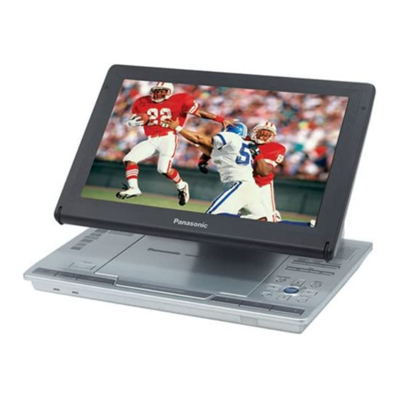
Portable DVD/CD PLAYER
DVD-LS90PP
DVD-LS93P
RAE1905Z-2C Mechanism Series
Colour
(S).................Silver Type
Discs played
[8cm (3") or 12cm (5")]:
Signal system:
LCD screen:
Composite-video output:
© 2005 Matsushita Electric Industrial Co., Ltd. All
rights
reserved.
distribution is a violation of law.
ORDER NO.CHM0503005CE
DVD (DVD-Video)
DVD-RAM (DVD-VR, JPEG(*1, 5))
DVD-R (DVD-Video)
DVD-RW (DVD-Video, DVD-VR)
+R/RW (Video)
CD, CD-R/RW [CD-DA, Video-CD,
SVCD(*1), MP3(*2, 5), WMA(*3, 5),
JPEG (*4, 5), HighMAT Level 2
(Audio and Image)]
*1: Conforming to IEC62107
*2: Compatible compression rate:
between 32 kbps and 320 kbps
*3: Compatible compression rate:
between 48 kbps and 320 kbps
*4: Exif Ver 2.1 JPEG Baseline files
Picture resolution: between 320×240
and 6144×4096 pixels (sub sampling
is 4:2:2 or 4:2:0)
*5: The total combined maximum
number of recognizalbe audio and
picture contents and groups: 4000
audio and picture contents and 400
groups.
NTSC
9"
-Si, TFT wide-screen LCD
Unauthorized
copying
B12
and
Advertisement
Table of Contents

Related Manuals for Panasonic DVD-LS93P


Summary of Contents for Panasonic DVD-LS93P
-
Page 1: Specifications
ORDER NO.CHM0503005CE Portable DVD/CD PLAYER DVD-LS90PP DVD-LS93P RAE1905Z-2C Mechanism Series Colour (S)....Silver Type Specifications Operating temperature Discs played DVD (DVD-Video) [8cm (3”) or 12cm (5”)]: range: +5 to +35°C (+41 to +95°F) DVD-RAM (DVD-VR, JPEG(*1, 5)) Operating humidity range: 5-85% RH (no condensation) - Page 2 DVD-LS90PP / DVD-LS93P Output level: 1Vp-p (75Ω) Voltage: 7.2V Output terminal: Mini-jack Capacity: 8600mAh Number of terminals: 1system Dimensions (excluding protrusions and battery): Audio output: DVD-LS90: 235.4(W) x 178.6(D) x 39.0*(H) mm Output level: 1.5Vrms (1kHz, 0dB, 10kΩ) ” (W) x 7 ”...
-
Page 3: Table Of Contents
DVD-LS90PP / DVD-LS93P CONTENTS Page Page 1 SAFETY PRECAUTIONS 12 Abbreviations 1.1. GENERAL GUIDELINES 13 VOLTAGE CHART 2 PREVENTION OF ELECTRO STATIC DISCHARGE (ESD) TO 13.1. MAIN P.C.B. ELECTROSTATICALLY SENSITIVE (ES) DEVICES 13.2. INVERTER P.C.B. 3 PRECAUTION OF LASER DIODE... -
Page 4: Safety Precautions
DVD-LS90PP / DVD-LS93P 1 SAFETY PRECAUTIONS 1.1. GENERAL GUIDELINES 1. When servicing, observe the original lead dress. If a short circuit is found, replace all parts which have been overheated or damaged by the short circuit. 2. After servicing, see to it that all the protective devices such as insulation barriers, insulation papers shields are properly installed. -
Page 5: Precaution Of Laser Diode
DVD-LS90PP / DVD-LS93P 8. Minimize bodily motions when handling unpackaged replacement ES devices. (Otherwise hamless motion such as the brushing together of your clothes fabric or the lifting of your foot from a carpeted floor can generate static electricity (ESD) sufficient to damage an ES device). -
Page 6: How To Replace The Lithium Battery
This model is using a lithium battery for the remote control ass’y. NOTE: The lithium battery is a critical component. ( Type No.: CR2025 Manufactured by Panasonic. ) It must never be subjected to excessive heat or discharge. It must therefore only be fitted in equipment designed specifically for its use. -
Page 7: Handling Precautions For Traverse Deck
DVD-LS90PP / DVD-LS93P 7 HANDLING PRECAUTIONS FOR TRAVERSE DECK The laser diode in the optical pickup may break down due to It has already been adjusted. potential difference caused by static electricity of clothes or human body. So be careful of electrostatic break down during repair of the optical pickup. -
Page 8: Disassembly, Reassembly And Service Position
DVD-LS90PP / DVD-LS93P 8 DISASSEMBLY, REASSEMBLY AND SERVICE POSITION... -
Page 9: Disassembly
DVD-LS90PP / DVD-LS93P 8.1. Disassembly... -
Page 10: Location
DVD-LS90PP / DVD-LS93P 8.2. P.C.B. location <Removing battery pack> Release the lock lever and remove the battery pack in the direction of the arrow. 1. Remove the 11 screws from the bottom of the unit. 8.3. Main cabinet of the unit... -
Page 11: Traverse Assembly
DVD-LS90PP / DVD-LS93P 8.4.2. Reinstalling traverse assembly 8.4. Traverse assembly 1. Reinstall the traverse assembly to the specified pin of the unit. 2. Reinstall the flexible cable of the optical pickpup unit and lock it securely. 3. Remove the solder of each laser short land of the flexible cable. -
Page 12: Optical Pick-Up Unit
DVD-LS90PP / DVD-LS93P 8.5. Optical pick-up unit 8.5.2. Reinstalling optical pick-up unit The optical pick-up unit is factory adjusted. Do not touch the 8.5.1. Removing optical pick-up unit adjustment screw. 1. Reassemble the disassembled parts in the reverse order of disassembly. -
Page 13: Main P.c.b
DVD-LS90PP / DVD-LS93P 8.7. Main P.C.B. 8.9. Monitor assembly 1. Unlock the connector and remove the flexible cable. 2. Remove the 3 connectors. 3. Remove the 4 screws and remove the main P.C.B.. 1. Unlock the connector and remove the flexible cable. -
Page 14: Disc Cover
DVD-LS90PP / DVD-LS93P 8.11. Monitor cover <Caution to be taken when installing monitor assembly> 1. Roll the flexible cable as shown figure. 1. Remove the 5 screws 2. Install the monitor assembly on the cabinet. 2. Remove the monitor cover into the direction of the arrow. -
Page 15: Mono Arm
DVD-LS90PP / DVD-LS93P 8.12. Mono arm 5. Release the latches and remove the mono arm 1. Remove the 2 screws. 2. Release the latches and remove the shaft covers. 3. Release the friction hinge from boss and remove the mono arm assembly. -
Page 16: Inverter P.c.b
DVD-LS90PP / DVD-LS93P 8.13. Inverter P.C.B. <Caution to be taken when installing mono arm> 1. Roll the flexible cables as shown figure and install it to 1. Unlock the connector and remove the flexible cable. mono arm cover. 2. Remove the connector and remove the inverter P.C.B. -
Page 17: Service Position
DVD-LS90PP / DVD-LS93P 8.15. Service position 8.15.1. Board checks 1. Connect the main P.C.B and the traverse assembly with an extension cable. 2. Install the traverse assembly to the tilt adjustment jig using three screws and three washers. Caution: · Remove the rubber cushion from the traverse assembly to prevent it from getting damaged. -
Page 18: Self-Diagnosis Function And Service Mode
DVD-LS90PP / DVD-LS93P 9 SELF-DIAGNOSIS FUNCTION AND SERVICE MODE 9.1. Optical Pickup Breakdown Diagnosis As a new feature, this unit has an “optical pick-up problem diagnosis function” and “a tilt adjustment confirmation function” built in. Use the following procedure to efficiently determine the problem and adjust tilt.If "NO DISC" is displayed, before exchanging the optical pick-up, carry out problem diagnosis first. -
Page 19: Uhf Displays
DVD-LS90PP / DVD-LS93P Cautions to be taken when replacing the optical pickup for short-circuiting or removing the laser diode. (Recommended soldering iron) HAKKO ESD Product The optical pickup may break down due to the static electricity of human body. Take proper protection measures 4. -
Page 20: Service Mode Table
DVD-LS90PP / DVD-LS93P 9.3. Service Mode Table 1 The service modes can be activated by pressing various button combination on the player and remote control unit. Player buttons Remote control unit buttons Application Note PAUSE Displaying the UHF display F_ _ _ Refer to section 9.2. -
Page 21: Last Error Code Saved During No Play
DVD-LS90PP / DVD-LS93P Error Code Error Content Additional error explanation Defect 1 Defect 2 Defect 3 Defect 4 F612 Access failure to ID data in DVD series (IC3001) specific time F630 No reply to KEY DET (for internal use only) -
Page 22: Service Mode Table
DVD-LS90PP / DVD-LS93P 9.6. Service mode table Pressing various button combinations on the player and remote control unit can activate the service modes. -
Page 23: Lens Cleaning
DVD-LS90PP / DVD-LS93P 9.7. Lens cleaning When cleaning the lens, use the lens cleaner which product part No. SZZP1038C. -
Page 24: Service Precautions
DVD-LS90PP / DVD-LS93P 10 SERVICE PRECAUTIONS 10.1. Recovery after the dvd player is repaired · When FROM or main P.C.B. is replaced, carry out the recovery processing to optimize the drive. Playback the recovery disk to process the recovery automatically. -
Page 25: Adjustment Procedures
DVD-LS90PP / DVD-LS93P 11 ADJUSTMENT PROCEDURES <Caution> Be sure to take static electricity countermeasures before adjusting the optical system. Adjust the optical systems according to the prescribed procedure. 11.1. Service Tools and Equipment Application Name Number Tilt adjustment DVD test disc... -
Page 26: Optical Adjustment
DVD-LS90PP / DVD-LS93P 11.4. Optical adjustment 11.4.1. Optical pick gate adjustment Measurement point Adjustment point Mode Disc Tangential adjustment screw Tracking servo "ON" DVDT-S01/S15 ----- (Adjustment screw A) Radial tilt adjustment screw Tracking servo "ON" (Adjustment screw B) Measuring apparatus... - Page 27 DVD-LS90PP / DVD-LS93P 11.4.1.2. Adjustment 1. Play back the disc (DVDT-S01/S15) and make sure the RF signal is outputted. 2. Play back the areas within a radius of 40 ± 1 mm of the disc (middle circumference). 3. Turn the adjustment screw C to minimize the jitter value in the radial direction.
-
Page 28: Electrical Adjustment (Lcd)
DVD-LS90PP / DVD-LS93P 11.5. Electrical adjustment (LCD) 11.5.2. Adjusting DC offset of impressed voltage [How to enter into the LCD panel adjustment mode] Adjustment is required when Check point Play back the specified video signal (10 steps, color bas Noise such as horizontal stripes TL8401 signal). -
Page 29: Electrical Check (Video Output Check)
DVD-LS90PP / DVD-LS93P 11.5.5. Adjusting amplitude of impressed 11.5.9. Adjusting color voltage Adjustment is required when Check point ----- TL8604 Adjustment is required when Check point Adjustment procedure Adjustment UP Adjustment ----- TL8401 DOWN Adjustment procedure Adjustment UP Adjustment Use “5” on remote control unit. -
Page 30: Abbreviations
DVD-LS90PP / DVD-LS93P 12 Abbreviations INITIAL/LOGO ABBREVIATIONS INITIAL/LOGO ABBREVIATIONS A0~UP ADDRESS ERROR TORQUE CONTROL ACLK AUDIO CLOCK ERROR TORQUE CONTROL AD0~UP ADDRESS BUS REFERENCE ADATA AUDIO PES PACKET DATA ENCSEL ENCODER SELECT ADDRESS LATCH ENABLE ETMCLK EXTERNAL M CLOCK (81MHz/40.5MHz) - Page 31 DVD-LS90PP / DVD-LS93P INITIAL/LOGO ABBREVIATIONS INITIAL/LOGO ABBREVIATIONS READ ENABLE VBLANK V BLANKING RFENV RF ENVELOPE COLLECTOR POWER SUPPLY RF PHASE DIFFERENCE OUTPUT VOLTAGE (CD-ROM) REGISTER SELECT VCDCONT VIDEO CD CONTROL (TRACKING RSEL RF POLARITY SELECT BALANCE) RESET DRAIN POWER SUPPLY VOLTAGE...
-
Page 32: Voltage Chart
DVD-LS90PP / DVD-LS93P 13 VOLTAGE CHART Note: · Indicated voltage values are the standard values for the unit measured by the DC electronic circuit tester (high-impedance) with the chassis taken as standard. Therefore, there may exist some errors in the voltage values, depending on the internal impedance of the DC circuit tester. - Page 33 DVD-LS90PP / DVD-LS93P IC3001 Ref No. MODE PLAY STOP IC3001 Ref No. MODE PLAY STOP Ref No. IC3001 MODE PLAY STOP IC3001 Ref No. MODE PLAY STOP IC3001 Ref No. MODE PLAY STOP IC3001 Ref No. MODE PLAY STOP IC3051 Ref No.
- Page 34 DVD-LS90PP / DVD-LS93P IC6201 Ref No. MODE PLAY STOP IC6301 Ref No. MODE PLAY STOP Ref No. IC6301 MODE PLAY STOP IC6301 IC6351 Ref No. MODE PLAY STOP Ref No. IC8001 MODE PLAY STOP IC8001 Ref No. MODE PLAY STOP IC8001 Ref No.
-
Page 35: Inverter P.c.b
DVD-LS90PP / DVD-LS93P Ref No. QR1413 QR1601 Q4001 QR4002 MODE PLAY STOP QR4003 QR4004 QR4005 QR4006 Ref No. MODE PLAY -2.0 STOP QR4007 QR4008 QR4009 QR4011 Ref No. MODE PLAY -1.0 -0.6 -0.6 STOP -0.7 QR4012 QR4013 QR5221 Ref No. - Page 36 DVD-LS90PP / DVD-LS93P...
-
Page 37: Block Diagram
DVD-LS90PP / DVD-LS93P 14 BLOCK DIAGRAM NOTE Circuit voltage and waveform described herein shall be regarded as reference information when probing defect point, because it may differ from an actual measuring value due to difference of Measuring instrument and its measuring condition and product itself. -
Page 38: Power Supply Block Diagram
DVD-LS90PP / DVD-LS93P 14.2. POWER SUPPLY BLOCK DIAGRAM IC6001 (OPERATION MPU) R.SKIP S6020 2 STICK F.SKIP S6019 AV SELECT Q1402 S6018 IP1401 D1401 D1404 JK1401 JK1401 DC IN POWER DC IN IC1401 OPERATION P.C.B. QR1402 STOP S6803 FP6801 FP6001 1 KEY... -
Page 39: Servo Block Diagram
DVD-LS90PP / DVD-LS93P 14.3. SERVO BLOCK DIAGRAM RF SIGNAL MOTOR DRIVE SIGNAL TRACKING ERROR SIGNAL FOCUS ERROR SIGNAL IC2601 OPTICAL PICK UP UNIT IC3001 (DV2.1) (TRAVERSE MOTOR DRIVE) VIN5 PHOTO DETECTOR VIN6 VIN7 HEAD VIN8 VIN1 VIN2 TRDRV VIN1 PWM1... -
Page 40: Audio Block Diagram
DVD-LS90PP / DVD-LS93P 14.4. AUDIO BLOCK DIAGRAM IC4001-14,15 IC3001-171 4.0Vp-p(0.5msec./div.) 5.5Vp-p(5usec./div.) IC4003 IC3001 IC4001 :AUDIO SIGNAL (AUDIO POWER AMP/DC VOLUME CONTROL) (DV2.1) (AUDIO DAC) DATA VOUTR ADOUT3 (DMIX OUT) AUDIO SRCK SERIAL PORT LRCK LRCK R-IN VOLUME BIAS CONTROL R-OUT-... -
Page 41: Video Block Diagram
DVD-LS90PP / DVD-LS93P 14.5. VIDEO BLOCK DIAGRAM IC8001-57 IC8001-52 :VIDEO SIGNAL IC8001-26 IC8001-21 IC8001-19 1.1Vp-p 1.2Vp-p 4.0Vp-p 4.0Vp-p 3.8Vp-p (20usec./div.) (20usec./div.) (20usec/div.) (20usec/div.) (20usec/div.) IC8001 LCD PANEL (VIDEO SIGNAL PROCESSOR) Q8001 Y IN PICTURE TRAP CONTROL R-OUT C IN DEMOD... - Page 42 DVD-LS90PP / DVD-LS93P...
-
Page 43: Interconnection Schematic Diagram & Schematic Diagram Notes
DVD-LS90PP / DVD-LS93P 15 INTERCONNECTION SCHEMATIC DIAGRAM & SCHEMATIC DIAGRAM NOTES 15.1. INTERCONNECTION SCHEMATIC DIAGRAM FP6801 FP6001 OPR+5V OPA+5V REMOIRQ REMOIRQ DGND DGND KEY2 KEY2 PLAY PLAY FP8005 FP1901 P1902 VCOM VCOM OPERATION P.C.B. STH1 STH1 GND(STH2) GND(STH2) GREEN GREEN... -
Page 44: Schematic Diagram Notes
DVD-LS90PP / DVD-LS93P 15.2. SCHEMATIC DIAGRAM NOTES This schematic diagram may be modified at any time with the development of new technology. Important safety notice: Components identified by mark have special characteristics important for safety. Furthermore, special parts which have purpose of fire-retardant (resistors), high-quality sound (capacitors), low-noise (resistors), etc. -
Page 45: Schematic Diagram
DVD-LS90PP / DVD-LS93P 16 SCHEMATIC DIAGRAM 16.1. CHARGE BATTERY SECTION (MAIN P.C.B. (1/9)) SCHEMATIC DIAGRAM (ADAPTOR) DC-IN BATTERY (SWTCHING) (SWTCHING) (SWTCHING) :CHG SECTION :PWR SECTION :SRV SECTION :OPU SECTION :DV2 SECTION :VOUT SECTION :AOUT SECTION :OPR SECTION :LCD SECTION (SWTCHING) -
Page 46: Power Supply Section (Main P.c.b. (2/9)) Schematic Diagram
DVD-LS90PP / DVD-LS93P 16.2. POWER SUPPLY SECTION (MAIN P.C.B. (2/9)) SCHEMATIC DIAGRAM (PWR-NG DET) (PWR-NG DET) (REG CONTROL) (REG A+5V) :CHG SECTION :PWR SECTION :SRV SECTION :OPU SECTION :DV2 SECTION :VOUT SECTION :AOUT SECTION :OPR SECTION :LCD SECTION (SWITCHING) (REG LCD+5V) -
Page 47: Servo Section (Main P.c.b. (3/9)) Schematic Diagram
DVD-LS90PP / DVD-LS93P 16.3. SERVO SECTION (MAIN P.C.B. (3/9)) SCHEMATIC DIAGRAM TO TRAVERSE MECHANISM UNIT :CHG SECTION :PWR SECTION :SRV SECTION :OPU SECTION :DV2 SECTION :VOUT SECTION :AOUT SECTION :OPR SECTION :LCD SECTION DVD-LS90PP/93P SERVO SECTION (MAIN P.C.B.(3/9)) SCHEMATIC DIAGRAM... -
Page 48: Optical Pick Up Section (Main P.c.b. (4/9))
DVD-LS90PP / DVD-LS93P 16.4. OPTICAL PICK UP SECTION (MAIN P.C.B. (4/9)) SCHEMATIC DIAGRAM (SWITCHING) RF SIGNAL PICK-UP UNIT (SWITCHING) (DVD LD SWITCHING) (DVD LD SWITCHING) :CHG SECTION :PWR SECTION :SRV SECTION :OPU SECTION :DV2 SECTION :VOUT SECTION :AOUT SECTION (CD LD SWITCHING) -
Page 49: Dv2 Section (Main P.c.b. (5/9)) Schematic Diagram
DVD-LS90PP / DVD-LS93P 16.5. DV2 SECTION (MAIN P.C.B. (5/9)) SCHEMATIC DIAGRAM :CHG SECTION RFKWPS81Z160 (16M FLASH ROM) :PWR SECTION VIDEO SIGNAL :SRV SECTION :OPU SECTION AUDIO SIGNAL :DV2 SECTION RF SIGNAL :VOUT SECTION :AOUT SECTION :OPR SECTION :LCD SECTION (FOR FLASH ROM WRITING) (EEPROM) (DV2.1) -
Page 50: Video Out Section (Main P.c.b. (6/9)) Schematic Diagram
DVD-LS90PP / DVD-LS93P 16.6. VIDEO OUT SECTION (MAIN P.C.B. (6/9)) SCHEMATIC DIAGRAM VIDEO SIGNAL (VIDEO DRIVE) VIDEO OUT :CHG SECTION :PWR SECTION :SRV SECTION :OPU SECTION :DV2 SECTION :VOUT SECTION DVD-LS90PP/93P :AOUT SECTION VIDEO OUT SECTION :OPR SECTION (MAIN P.C.B.(6/9)) -
Page 51: Audio Out Section (Main P.c.b. (7/9)) Schematic Diagram
DVD-LS90PP / DVD-LS93P 16.7. AUDIO OUT SECTION (MAIN P.C.B. (7/9)) SCHEMATIC DIAGRAM AUDIO SIGNAL HEAD PHONES (AUDIO POWER AMP) (MUTE) (MUTE) HEAD PHONES (MUTE) (MUTE) (REG) (MUTE) OPT OUT (MUTE) AUDIO OUT (MUTE) (AUDIO DAC) (JACK-IN DET) (AMP) :CHG SECTION... -
Page 52: Operation Section (Main P.c.b. (8/9)) Schematic Diagram
DVD-LS90PP / DVD-LS93P 16.8. OPERATION SECTION (MAIN P.C.B. (8/9)) SCHEMATIC DIAGRAM TO FP6801 OPERATION P.C.B. (OPERATION MPU) (VOL AMP) :CHG SECTION :PWR SECTION :SRV SECTION :OPU SECTION :DV2 SECTION :VOUT SECTION :AOUT SECTION :OPR SECTION :LCD SECTION DVD-LS90PP/93P OPERATION SECTION (MAIN P.C.B.(8/9)) -
Page 53: Lcd If Section (Main P.c.b. (9/9)) Schematic Diagram
DVD-LS90PP / DVD-LS93P 16.9. LCD IF SECTION (MAIN P.C.B. (9/9)) SCHEMATIC DIAGRAM 3300 (REG) TO FP1901 INVERTER P.C.B. TL8602 TL8603 TL8604 G1C1R5JA0041 (CONTROLLER) (REG 5V) SPEAKER(L) SPEAKER(R) (BUFFER) 002192 (I NV.) (EEPROM) (AMP) :CHG SECTION (AMP) :PWR SECTION :SRV SECTION... -
Page 54: Operation Section (Operation P.c.b.) Schematic Diagram
DVD-LS90PP / DVD-LS93P 16.10. OPERATION SECTION (OPERATION P.C.B.) SCHEMATIC DIAGRAM TO FP6001 MAIN P.C.B. DVD-LS90PP/93P OPERATION P.C.B. SCHEMATIC DIAGRAM... -
Page 55: Inverter Section Schematic Diagaram
DVD-LS90PP / DVD-LS93P 16.11. INVERTER SECTION SCHEMATIC DIAGARAM VIDEO SIGNAL TO FP8005 MAIN P.C.B. LCD PANEL (INV.CTL) (INV.) TO BACK LIGHT PANEL DVD-LS90PP/93P INVERTER P.C.B. SCHEMATIC DIAGRAM... - Page 56 DVD-LS90PP / DVD-LS93P...
-
Page 57: Circuit Board Assembly
DVD-LS90PP / DVD-LS93P 17 CIRCUIT BOARD ASSEMBLY 17.1. MAIN P.C.B. (1/2) (COMPONENT SIDE) MAIN P.C.B. (1/2) DVD-LS90PP/93P (COMPONENT SIDE) MAIN P.C.B. (1/2) (RFKBLS90MP) -
Page 58: Main P.c.b. (2/2) (Foil Side)
DVD-LS90PP / DVD-LS93P 17.2. MAIN P.C.B. (2/2) (FOIL SIDE) MAIN P.C.B. (2/2) MAIN P.C.B. Transistors IC3051 F CL3007 C CL5204 Q1001 C IC3201 F CL3008 C CL5205 Q1002 C IC4001 C CL3009 C CL6001 Q1003 C IC4002 C CL3010 C CL6002... -
Page 59: Operation & Inverter P.c.b
DVD-LS90PP / DVD-LS93P 17.3. OPERATION & INVERTER P.C.B. OPERATION P.C.B. INVERTER P.C.B. (1/2) INVERTER P.C.B. (2/2) OPERATION P.C.B. LCD P.C.B. Test Points Transistor TL6801 Q1901 TL6802 Integrated Circuit TL6803 IC1901 TL6804 Test Points TL6805 TL1901 TL6805 TL1902 TL6807 TL1903 TL6808... - Page 60 DVD-LS90PP / DVD-LS93P...
-
Page 61: Exploded Views
DVD-LS90PP / DVD-LS93P 18 EXPLODED VIEWS 18.1. Casing Parts & Mechanism Section Exploded View... -
Page 62: Mechanism Section Exploded View
DVD-LS90PP / DVD-LS93P 18.2. Mechanism Section Exploded View... -
Page 63: Packing & Accessories Exploded View
DVD-LS90PP / DVD-LS93P 18.3. Packing & Accessories Exploded View... -
Page 64: Replacement Parts List
DVD-LS90PP / DVD-LS93P 19 REPLACEMENT PARTS LIST Notes: Ref. Part No. Part Name & Remarks Description *Important safety notice: RMB0833 OPEN SPRING Components identified mark have special RMB0834 OPEN BUTTON SPRING RMG0681-K SPEAKER RUBBER characteristics important for safety. RML0699 LOCK LEVER... - Page 65 DVD-LS90PP / DVD-LS93P Ref. Part No. Part Name & Remarks Ref. Part No. Part Name & Remarks Description Description C1063 F1K1C106A062 16V 10U C2034 ECJ1XB1C104K 16V 0.1U C1066 ECJ1VB1H103K 50V 0.01U C2501 F1H1H101A799 50V 100P C1067,6 ECJ1VF1C104Z 16V 0.1U C2601...
- Page 66 DVD-LS90PP / DVD-LS93P Ref. Part No. Part Name & Remarks Ref. Part No. Part Name & Remarks Description Description C4007,0 ECJ1VB1H102K 50V 1000P C8013- ECJ1XB1C104K 16V 0.1U C4009,1 ECJ1VB0J474K 6.3V 0.47U C8016- ECJ1VB0J105K 6.3V 1U C4011,1 F2G0G331A012 4V 330U C8020- ECUM1A225KBN 10V 2.2U...
- Page 67 DVD-LS90PP / DVD-LS93P Ref. Part No. Part Name & Remarks Ref. Part No. Part Name & Remarks Description Description D1401,0 JVCRB051L40T DIODE B0JCPE000004 IC8801 AN78L05M-E1 AN78L05ME1 IC8802 C0CBABC00147 D1404 JVCRB051L40T DIODE B0JCPE000004 D1405 SFPA-73V DIODE B0JCPD000003 IP1401 K5H3121A0004 IC PROTECTOR...
- Page 68 DVD-LS90PP / DVD-LS93P Ref. Part No. Part Name & Remarks Ref. Part No. Part Name & Remarks Description Description LB8801- ERJ3GEY0R00 1/10W 0 R1040 ERJ3RBD122 1/16W 1.2K R1044,4 ERJ3GEYJ102V 1/10W 1K LB8808- J0JHC0000045 COIL R1060 ERJ3GEYJ151V 1/10W 150 R1061 ERJ3GEYJ822 1/10W 8.2K...
- Page 69 DVD-LS90PP / DVD-LS93P Ref. Part No. Part Name & Remarks Ref. Part No. Part Name & Remarks Description Description R3013 ERJ3GEYJ105V 1/10W 1M R5208,0 ERJ3GEYJ331 1/10W 330 R3014 ERJ3GEYJ271 1/10W 270 R5210 ERJ3GEYJ100 1/10W 10 R3015 ERJ3GEY0R00 1/10W 0 R5211 ERJ3GEYJ2R2 1/10W 2.2...
- Page 70 DVD-LS90PP / DVD-LS93P Ref. Part No. Part Name & Remarks Ref. Part No. Part Name & Remarks Description Description R8221 ERJ3GEYJ151V 1/10W 150 S6806 K0H1BA000432 SWITCH R8222 ERJ3GEYJ101 1/10W 100 D0GB101JA002 S6807 K0H1BA000432 SWITCH R8223 ERJ3GEYJ820 1/10W 82 S6808 K0H1BA000432...