Table of Contents
Advertisement
SERVICE MANUAL
Ver 1.1 2002.06
Hcd-Gr8/Rx90 is the tuner, deck, CD and
amplifier section in MHC-GR8/RX90.
*
Dolby noise reduction manufactured
under license from Dolby Laboratories
Licensing corporation.
"DOLBY" and the double-D symbol a
are trademarks of Dolby Laboratories
Licensing Corporation.
Amplifier section
DIN power output (RX90)
80+80 watts
(8 ohms, at 1kHz, DIN)
Continuous RMS power output
RX90:
100+100 watts
(8ohms at 1kHz, 10% THD)
GR8:
90+90 watts
(8ohms at 1kHz, 10% THD)
Peak music power output
GR8:
1500 watts
Music power output
RX90:
160+160 watts
(8ohms at 1kHz, 10% THD)
Inputs
VIDEO/MD IN (phono jacks):
voltage 250 mV, impedance
47 kilohms MIX MIC (phone
jack): sensitivity 1 mV,
impedance 10 kilohms
Outputs
VIDEO/MD OUT (phone
jacks): voltage 250 mV
impedance 1 kilohms
PHONES (stereo phone jack):
accepts headphones of 8 ohms
or more.
SPEAKER:
accepts impedance of 8 to 16
ohms
Sony Corporation
9-960-881-12
2002F0500-1
Home Audio Company
C 2002.06
Published by Sony Engineering Corporation
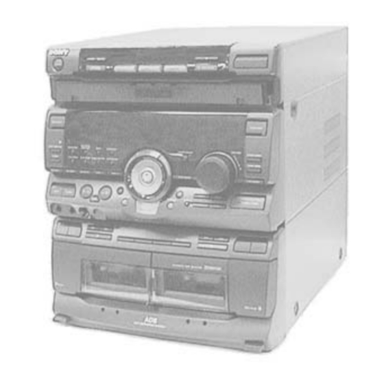
HCD-GR8/RX90
Photo: HCD-RX90
CD
Section
Tape deck
Section
SPECIFICATIONS
SURROUND SPEAKER:
accepts impedance of 16
ohms.
SUPER WOOFER:
Voltage 1 V, impedance 1 kilo
ohm
CD player section
System
Compact disc and digital
audio system
Laser
Semiconductor laser
(λ=780 nm)
Emission duration: continuous
Laser output
Max. 44.6 µW*
*This output is the value
measured at a distance of 200
mm from the objective lens
surface on the Optical Pick-up
Block with 7 mm aperture.
Frequency response 2 Hz – 20 kHz (±0.5 dB)
Wavelength
780 – 790 nm
MINI Hi-Fi COMPONENT SYSTEM
Australian Model
Model Name Using Similar Mechanism
CD Mechanism Type
Base Unit Name
Optical Pick-up Name
Model Name Using Similar Mechanism
Tape Transport Mechanism Type
Signal-to-noise ratio More than 90 dB
Dynamic range
CD OPTICAL DIGITAL OUT
(Square optical connector jack, rear panel)
Wavelength
Output Level
Tape player section
Recording system
Frequency response 60 – 13,000 Hz (±3 dB),
(DOLBY NR OFF) using Sony TYPE I casstte
Wow and flutter
AEP Model
UK Model
HCD-RX90
E Model
Tourist Model
HCD-GR8
HCD-GR7/RX70
CDM38L-5BD29AL
BU-5BD29AL
KSS-213D/Q-NP
HCD-H881
TCM-220WR2
More than 90 dB
600 nm
–18 dBm
4-track 2-channel stereo
60 – 14,000 Hz (±3 dB),
using Sony TYPE II cassette
±0.15% W.Peak (IEC)
0.1% W.RMS (NAB)
±0.2% W.Peak (DIN)
– Continued on next page –
Advertisement
Table of Contents

Related Manuals for Sony HCD-GR8


Summary of Contents for Sony HCD-GR8
- Page 1 UK Model HCD-RX90 Ver 1.1 2002.06 E Model Australian Model Tourist Model HCD-GR8 HCD-GR8/RX90 is the tuner, deck, CD and amplifier section in MHC-GR8/RX90. Photo: HCD-RX90 Dolby noise reduction manufactured Model Name Using Similar Mechanism HCD-GR7/RX70 under license from Dolby Laboratories Licensing corporation.
- Page 2 Approx. 9.5 kg Supplied accessories: AM loop aerial (1) EA3 : Saudi Arabia Remote RM-SD80 (1) EA4 : Israeli Sony SUM-3 (NS) : East European Batteries (2) : German FM lead aerial (1) HK : Hong Kong Speaker cords (4)
- Page 3 LINE WITH MARK ! ON THE SCHEMATIC DIAGRAMS AND IN THE PARTS LIST ARE CRITICAL TO SAFE OPERATION. REPLACE THESE COMPONENTS WITH SONY PARTS WHOSE PART NUMBERS APPEAR AS SHOWN IN THIS MANUAL OR IN SUPPLEMENTS PUB- LISHED BY SONY.
- Page 4 TABLE OF CONTENTS SERVICING NOTES NOTES ON HANDLING THE OPTICAL PICK-UP Servicing Notes ................BLOCK OR BASE UNIT The laser diode in the optical pick-up block may suffer electrostatic GENERAL ..............break-down because of the potential difference generated by the charged electrostatic load, etc.
- Page 25 SECTION 2 DISASSEMBLY • This set can be disassembled in the order shown below. FRONT PANEL OPTICAL CD MECHANISM BASE UNIT BD BOARD CASE SECTION PICK-UP DECK SECTION (Page 27) (Page 29) (Page 25) (Page 25) (Page 26) (Page 29) MAIN BOARD (Page 27) SLED...
- Page 26 CD MECHANISM DECK SECTION 1 two connectors (CN203, 204) 3 two screws (BVTP 3 × 8) 2 flat wire 4 CD mechanism deck section (CN202) Note: The CD mechanism deck will fall if three screws are removed. Support it by hand, then remove three screws.
- Page 27 BASE UNIT 2 boss 1 two yoke bracket 3 base unit MAIN BOARD 4 four screws (BVTP 3 × 8) 1 connector (CN901) 2 connector (CN105) 3 flat wire (CN201) IC201 6 main board 4 two screws (BVTP 3 × 8) 5 connector (CN101) –...
- Page 28 TRAY SECTION claw A claw B 3 flat wire (CN705) flat wire Note: When installing the tray, pull around the flat 4 two claws wire to pass through the claw A and claw B , as shown in the figure. 2 Pull the tray.
- Page 29 BD BOARD 1 two screws 1 two screws (PTPWH M2.6 × 6) (PTPWH M2.6 × 6) 2 optical pick-up section 3 two springs 3 two springs 5 screw 4 flat wire (BVTP 2.6 × 8) (CN101) 6 Removal 7 BD board the four solders.
- Page 30 AUDIO BOARD 1 connector 2 two rivets (CN651) 4 four screws (BTP 2.6 × 4) 3 Break the soldering of two flexible flat cables. 5 AUDIO board CAPSTAN MOTOR 4 Removal the capstan motor to direction of the arrow. 2 two screws (BTP 2.6 ×...
- Page 31 SECTION 3 TEST MODE [MC Cold Reset] [Change-over of AM Tuner Step between 9kHz and 10kHz] • The cold reset clears all data including preset data stored in the • A step of AM channels can be changed over between 9kHz and RAM to initial conditions.
- Page 32 [Aging Mode] 7. In the aging mode, the aging is executed in a sequence given in “2-2. Operation during Aging Mode”. This mode can be used for operation check of CD section and tape The aging continues unless an alarm occurred. deck section.
-
Page 33: Mechanical Adjustments
SECTION 4 SECTION 5 MECHANICAL ADJUSTMENTS ELECTRICAL ADJUSTMENTS PRECAUTION DECK SECTION 0 dB=0.775V 1. Clean the following parts with a denatured-alcohol-moistened swab: 1. Demagnetize the record/playback head with a head demagne- record/playback head pinch roller tizer. (Do not bring the head demagnetizer close to the erase erase head rubber belts head.) - Page 34 2. Turn the adjustment screw and check output peaks. If the peaks Tape Speed Adjustment DECK A do not match for L-CH and R-CH, turn the adjustment screw Note: Start the Tape Speed adjustment as below after setting to the so that outputs match within 1dB of peak.
- Page 35 Record bias Current Adjustment DECK B Adjustment Location: main board Procedure: [MAIN BOARD] (Component Side) 1. Mode: record Pin 6 (L-CH) of IC1501 on the main board. RV1501 Pin #¶ (L-CH) of IC1501 on the main board. 1) 315 Hz IC1501 ...
- Page 36 TUNER SECTION 0 dB=1 µV (GR8: Tourist/RX90 only) Note: As a front-end (FE1) is difficult to repair if faulty, replace it with new one. AM Section Adjustment Setting: loop antenna loop antenna (Supplied accessories) AM RF SSG 30% amplitude modulation by AM ANTENNA 60 cm 400 Hz signal...
- Page 37 SW OSC Voltage Adjustment Adjustment Location: (GR8: Tourist only) [TCB BOARD] (Component Side) Setting: Band: SW RV41 D1, CV2, T2 Procedure: SW OSC Voltage 1. Connect digital Voltmeter to diode D1 center lead and ground. Adjustment 2. Adjust for a following value reading on digital voltmeter. CV2 CV1 frequency part...
- Page 38 FM Polar Adjustment (RX90: EE, CIS only) Procedure : 1. Set the modulation of FM RF SSG to AUDIO 1 kHz, 10 kHz deviation according to "Connection 1". Connection 1: 2. Tune the set to 69 MHZ. FM RF SSG 3.
- Page 39 S Curve Check CD SECTION oscilloscope Note: 1. CD Block is basically designed to operate without adjustment. BD board Therefore, check each item in order given. TP (FEO) 2. Use YEDS-18 disc (3-702-101-01) unless otherwise indicated. TP (VC) – 3. Use an oscilloscope with more than 10M impedance. 4.
- Page 40 E-F Balance (1 Track Jump) check Adjustment Location: (Without remote commander) [BD BOARD] (Conductor Side) oscilloscope BD board TP (TEO) TP (VC) – IC101 Procedure: 1. Connect oscilloscope to test point TP (TEO) on BD board. 2. Turned Power switch on. 3.
- Page 41 SECTION 6 DIAGRAMS • Circuit Boards Location TRANS board TCB board (GR8: Tourist/RX90) ENCAPSULATED COMPONENT (EXCEPT GR8: Tourist/RX90) DECO board CD SW board PANEL board HP/MIC board DJ board MAIN board TC SW board POWER AMP board SENSOR board MOTOR (TURN) board CONNECTOR board MOTOR board BD board...
-
Page 55: Ic Block Diagrams
• IC Block Diagrams IC21 LC72130 (TCB BOARD) PHASE DETECTOR CHARGE PUMP UNLOCK POWER DETECTOR RESET REFERENCE SWALLOW COUNTER DIVIDER 1/16, 1/17 4BITS 12BITS PROGRAMMABLE DRIVER UNIVERSAL DATA SHIFT REGISTER LATCH COUNTER 3 4 5 6 IC41 LA1835 (TCB BOARD) 17 16 DECODER RF. - Page 56 IC1701 IR3R42 (TCB BOARD) 19 18 14 13 PHASE COMPARATOR PHASE PHASE COMPARATOR 2 TRIGGER WAVEFORM SEP. REGULATOR SAMPLE MUTE GATE & HOLD BUFFER IC1702 MC14053BCP (TCB BOARD) B.COM OPEN A.COM C.COM OPEN OPEN – 83 –...
- Page 57 IC101 CXA1992AR (BD BOARD) – RF SUMMING PD2 IV PD1 IV FE_BIAS SENS2 ↓ – SENS1 LASER POWER CONTROL F IV AMP FE AMP C. OUT – E IV AMP – DFCT XRST – LEVEL S DATA FO. BIAS WINDOW MIRR COMP.
- Page 58 IC102 BA5941FP-E2 (BD BOARD) – + – + – LEVEL SHIFT LEVEL SHIFT LEVEL SHIFT – LEVEL SHIFT – – + – – + – MUTE IC103 CXD2519Q (BD BOARD) 80 79 78 77 76 75 74 73 72 71 70 69 68 67 66 65 64 63 62 61 60 59 58 57 56 55 54 53 52 51 LRCK AVSS WDCK...
- Page 59 IC281 µPC1237HA (MAIN BOARD) IC751 M65850P (HP/MIC BOARD) OVER LOAD DET MUTE OFFSET DET OSCILLATOR LPF2 1/2 VCC LATCH/ CLOCK AUTORESET AUTO MAIN 20KBIT RESET RESET CONTROL SRAM AC OFF LPF1 IC602 µPC1330HA (AUDIO BOARD) INVERTER COMPARATER SW R1 GND SW P1 CONT GND SW P2 GND SW R2...
- Page 60 IC901 LA5617 (MAIN BOARD) CURRENT CURRENT START ON/OFF ON/OFF LIMITER LIMITER CIRCUIT VREF VMUTE OVER HEAT PROTECT VREF ERROR VREF ~ _ 1.8V ERROR IC1502 LB1641(MAIN BOARD) T.S.D O.C.P MOTOR MOTOR DRIVE DRIVE FWD/REV/STOP CONTROL LOGIC IC401 MSM6653A-485RS (DJ BOARD) I3/PORT1 544KBIT ROM I2/PORT0...
- Page 61 6-15. IC PIN FUNCTION DESCRIPTION MAIN BOARD IC301 µPD780018YGF-011-3BA (MASTER CONTROL) Pin No. Pin Name Function TA-MUTE Line mute signal output DBFB-H/L DBFB H/L select signal output 427-LAT Latch signal output for IC201 (M62427FP) K-CON-LAT Not used K-CON-ON F-RELAY Main speaker relay control output R-RELAY Surround speaker relay control output PL-RELAY...
- Page 62 Pin No. Pin Name Function COM-DOUT Common serial data output COM-CLK Common serial clock output CD-POWER CD power on signal output CD-DATA CD data output CD-CLK CD clock output MSM-CND DJ effect command output MSM-BUSY Busy signal input MSM-LAT Serial latch pulse output MSM-NAR NAR signal input MSM-CH...
- Page 63 Pin No. Pin Name Function PB-A/B PB Deck A/Deck B select output EQ-H/N Equalizer H/N select output BIAS Bias ON/OFF signal output REC-MUTE REC mute ON/OFF selection output NR-ON/OFF NR ON/OFF signal output R/P-PASS REC/PB/PASS selection output TC-MUTE TC mute ON/OFF selection output A-PLAY-SW Deck A play detect B-PLAY-SW...
- Page 64 PANEL BOARD IC601 TMP87CH75F-6543 (GRAPHIC CONTROL) Pin No. Pin Name Function SEG-35 Fluorescent display tube segment signal output V-LOAD – –30V for Fluorescent display tube 3-10 LED1-LED8 LED driver output – Ground X-OUT X'tal (8MHz) X-IN X'tal (8MHz) RESET Reset signal input from master control 15, 16 LED9, LED10 LED driver output TEST...
-
Page 65: Exploded Views
Ver 1.1 SECTION 7 EXPLODED VIEWS NOTE: • -XX and -X mean standardized parts, so they • Items marked “*” are not stocked since they The components identified by mark ! or dotted line with mark ! are are seldom required for routine service. Some may have some difference from the original critical for safety. - Page 66 Ver 1.1 Ref. No. Part No. Description Remark Ref. No. Part No. Description Remark 4-990-129-01 SPRING (OPEN A) (GR8: EA3, EA4, MY, SAF, TH) 4-989-904-11 SPRING (B DECK) 4-990-129-11 SPRING (OPEN A) (EXCEPT GR8: EA3, EA4, MY, X-4947-923-1 LID (B) ASSY, CASSETTE (BLACK) SAF, TH) (GR8: E2, MX/RX90: AEP, AED, G, UK) 4-951-620-01 SCREW (2.6X8), +BVTP...
- Page 67 Ver 1.1 (2) FRONT PANEL SECTION GR8: EA3 not supplied not supplied not supplied supplied with S602 – 94 –...
- Page 68 (RX90: AEP, AED, G, UK) 4-984-085-01 SPRING (ENTER), COMPRESSION * 68 A-4392-382-A PANEL BOARD, COMPLETE (RX90: EE, CIS) 4-962-708-21 EMBLEM (4-A), SONY * 68 A-4392-383-A PANEL BOARD, COMPLETE (GR8: E2, E3, HK, IA, MX, SP, TW, AUS, JE) 4-986-859-11 WINDOW (CD)
- Page 69 (3) CHASSIS SECTION CDM38L-5BD29AL E3, IA, E, IA, MX, JE GR8: HK, AUS RX90: UK EA3, SP, AEP, AED, EE, CIS, G, EA3, EA4, HK, MY, not supplied SAF, SP, TW T901 M901 not supplied – 96 –...
- Page 70 Ref. No. Part No. Description Remark Ref. No. Part No. Description Remark * 101 A-4392-375-A POWER AMP BOARD, COMPLETE 1-773-012-11 WIRE (FLAT TYPE) (15 CORE) (GR8: E3, EA3, (RX90: AEP, AED, EE, CIS, G, UK) HK, IA, MY, SAF, SP, TW, JE/RX90) * 101 A-4392-376-A POWER AMP BOARD, COMPLETE * 109...
- Page 71 (4) CD MECHANISM DECK SECTION-1 (CDM38L-5BD29AL) M701 Ref. No. Part No. Description Remark Ref. No. Part No. Description Remark 4-917-583-21 BRACKET, YOKE 4-977-941-01 BEARING (WORM) 4-977-945-01 TRAY (TURN) * 209 1-658-576-11 SENSOR BOARD X-4946-665-1 SHAFT ASSY, WORM 4-934-376-01 SHAFT (ROLLER) 4-977-943-01 BELT (TURN) (1.2) 4-977-944-01 TRAY (SLIDE) 4-977-956-01 WHEEL, WORM...
- Page 72 (5) CD MECHANISM DECK SECTION-2 (CDM38L-5BD29AL) M801 BU-5BD29AL S811 Ref. No. Part No. Description Remark Ref. No. Part No. Description Remark 4-917-583-71 BRACKET, YOKE 4-951-620-41 SCREW (2.6), +BVTP 4-977-954-01 PULLEY (SL) * 265 X-4946-666-1 HOLDER (BU) ASSY 4-977-953-01 GEAR (SL-A) 4-989-494-01 SCREW (SLIDER), STEP 4-977-955-01 GEAR (SL-B) 4-989-492-11 SLIDER (38) (GR8: EA3, EA4, MY, SAF, TH)
- Page 73 (6) BASE UNIT SECTION (BU-5BD29AL) M101 M102 The components identified by mark ! or dotted line with mark ! are critical for safety. Replace only with part number specified. Ref. No. Part No. Description Remark Ref. No. Part No. Description Remark ! 301 8-820-020-01 OPTICAL PICK-UP KSS-213D/Q-NP...
- Page 74 (7) TAPE MECHANISM DECK SECTION-1 (TCM-220WR2) (including r C) HP101 (including r A) not supplied not supplied not supplied HRPE101 (including r B) not supplied not supplied not supplied not supplied Ref. No. Part No. Description Remark Ref. No. Part No. Description Remark 3-908-560-01 SPRING, AZIMUTH ADJUSTMENT...
- Page 75 (8) TAPE MECHANISM DECK SECTION-2 (TCM-220WR2) r C: MOTOR board supplied Ref. No. Part No. Description Remark Ref. No. Part No. Description Remark 3-908-597-01 CAM (A) X-3370-171-1 FLYWHEEL (BR) ASSY 3-908-608-11 SCREW, STEP 3-908-600-01 LEVER (REV-B) X-3372-930-1 ARM (A) ASSY, FR * 416 1-650-669-11 LEAF SWITCH BOARD X-3370-169-1 FLYWHEEL (AR) ASSY...
- Page 76 SECTION 8 AUDIO ELECTRICAL PARTS LIST NOTE: • Due to standardization, replacements in the • Items marked “*” are not stocked since they The components identified by mark ! or dotted line with mark ! are parts list may be different from the parts speci- are seldom required for routine service.
- Page 77 AUDIO Ref. No. Part No. Description Remark Ref. No. Part No. Description Remark R314 1-247-882-11 CARBON 130K 1/4W C107 1-164-161-11 CERAMIC CHIP 0.0022uF 10% 100V R315 1-247-850-11 CARBON 6.2K 1/4W C108 1-164-232-11 CERAMIC CHIP 0.01uF R331 1-249-430-11 CARBON 1/4W C109 1-164-232-11 CERAMIC CHIP 0.01uF C110...
- Page 78 CD SW Ref. No. Part No. Description Remark Ref. No. Part No. Description Remark < CONNECTOR > R136 1-216-073-00 METAL CHIP 1/10W CNU101 1-777-937-11 CONNECTOR, FFC/FPC 16P R137 1-216-065-00 METAL CHIP 4.7K 1/10W CNU102 1-778-874-11 CONNECTOR, FFC(LIF(NON-ZIF))19P R138 1-216-025-91 METAL GLAZE 1/10W R156 1-216-081-00 METAL CHIP...
- Page 79 CD SW CONNECTOR DECO Ref. No. Part No. Description Remark Ref. No. Part No. Description Remark D628 8-719-056-13 DIODE SML79423C-TP15 S654 1-554-303-21 SWITCH, TACTILE (· ∏) (DISC IN/PLAY: DISC 2) D629 8-719-056-13 DIODE SML79423C-TP15 ************************************************************* (DISC IN/PLAY: DISC 2) D630 8-719-056-13 DIODE SML79423C-TP15 1-658-575-11 CONNECTOR BOARD (DISC IN/PLAY: DISC 3)
- Page 80 HP/MIC Ref. No. Part No. Description Remark Ref. No. Part No. Description Remark C403 1-126-963-11 ELECT 4.7uF C761 1-162-282-31 CERAMIC 100PF C404 1-164-159-11 CERAMIC 0.1uF C762 1-126-961-11 ELECT 2.2uF C407 1-126-963-11 ELECT 4.7uF C764 1-126-964-11 ELECT 10uF C765 1-126-960-11 ELECT <...
- Page 81 HP/MIC LEAF SWITCH MAIN Ref. No. Part No. Description Remark Ref. No. Part No. Description Remark < INDUCTOR > < RESISTOR > L751 1-410-521-11 INDUCTOR 100uH (GR8: EA3) R1001 1-247-818-11 CARBON 1/4W R1002 1-247-820-11 CARBON 1/4W < RESISTOR > R1003 1-249-414-11 CARBON 1/4W R1004...
- Page 82 MAIN Ref. No. Part No. Description Remark Ref. No. Part No. Description Remark C191 1-126-963-11 ELECT 4.7uF C291 1-126-959-11 ELECT 0.47uF C192 1-164-159-11 CERAMIC 0.1uF C301 1-126-967-11 ELECT 47uF C201 1-136-169-00 FILM 0.22uF C302 1-164-159-11 CERAMIC 0.1uF C202 1-136-169-00 FILM 0.22uF C303 1-136-165-00 FILM...
- Page 83 MAIN Ref. No. Part No. Description Remark Ref. No. Part No. Description Remark C1523 1-126-933-11 ELECT 100uF D307 8-719-987-63 DIODE 1N4148M D902 8-719-024-99 DIODE 11ES2-NTA2B C1531 1-164-159-11 CERAMIC 0.1uF D903 8-719-024-99 DIODE 11ES2-NTA2B C1532 1-164-159-11 CERAMIC 0.1uF D904 8-719-024-99 DIODE 11ES2-NTA2B C1533 1-164-159-11 CERAMIC 0.1uF...
- Page 84 MAIN Ref. No. Part No. Description Remark Ref. No. Part No. Description Remark L393 1-410-515-11 INDUCTOR 33uH R131 1-260-076-11 CARBON 1/2W (RX90) < TRANSISTOR > R132 1-260-076-11 CARBON 1/2W (RX90) Q101 8-729-141-30 TRANSISTOR 2SC3623A-LK R133 1-260-091-11 CARBON 1/2W Q102 8-729-900-63 TRANSISTOR DTA124ES Q103 8-729-900-36 TRANSISTOR DTC124ES R134...
- Page 85 MAIN Ref. No. Part No. Description Remark Ref. No. Part No. Description Remark R293 1-249-417-11 CARBON 1/4W R218 1-249-413-11 CARBON 1/4W R294 1-249-441-11 CARBON 100K 1/4W R219 1-249-429-11 CARBON 1/4W R295 1-247-903-00 CARBON 1/4W R221 1-249-425-11 CARBON 4.7K 1/4W R301 1-249-413-11 CARBON 1/4W R222...
- Page 86 MAIN Ref. No. Part No. Description Remark Ref. No. Part No. Description Remark R342 1-247-807-31 CARBON 1/4W R1506 1-249-421-11 CARBON 2.2K 1/4W R343 1-247-807-31 CARBON 1/4W R344 1-247-807-31 CARBON 1/4W R1507 1-249-428-11 CARBON 8.2K 1/4W R1521 1-249-430-11 CARBON 1/4W R345 1-247-807-31 CARBON 1/4W R1522...
- Page 87 MOTOR MOTOR (SLIDE) MOTOR (TURN) PANEL Ref. No. Part No. Description Remark Ref. No. Part No. Description Remark < IC > MOTOR BOARD IC701 8-759-633-65 IC M54641L ************* (Included in AUDIO BOARD, COMPLETE) < RESISTOR > < CAPACITOR > R706 1-249-411-11 CARBON 1/4W C651...
- Page 88 PANEL Ref. No. Part No. Description Remark Ref. No. Part No. Description Remark C636 1-126-160-11 ELECT < IC > C637 1-136-161-00 FILM 0.047uF 5% C638 1-124-464-11 ELECT 0.22uF IC601 8-759-446-27 IC TMP87CH75F-6543 C639 1-124-464-11 ELECT 0.22uF IC602 8-759-332-18 IC GP1U27XB C640 1-162-306-11 CERAMIC 0.01uF...
- Page 89 PANEL Ref. No. Part No. Description Remark Ref. No. Part No. Description Remark R631 1-249-417-11 CARBON 1/4W R685 1-249-419-11 CARBON 1.5K 1/4W R632 1-249-419-11 CARBON 1.5K 1/4W R686 1-247-897-11 CARBON 560K 1/4W R633 1-249-421-11 CARBON 2.2K 1/4W R687 1-249-437-11 CARBON 1/4W R634 1-249-419-11 CARBON...
- Page 90 PANEL POWER AMP Ref. No. Part No. Description Remark Ref. No. Part No. Description Remark S633 1-554-303-21 SWITCH, TACTILE (MOVIE) < CONNECTOR > S634 1-554-303-21 SWITCH, TACTILE (MUSIC) S635 1-554-303-21 SWITCH, TACTILE (EFFECT ON/OFF) CN801 1-778-981-11 CONNECTOR, BOARD TO BOARD 13P S636 1-554-303-21 SWITCH, TACTILE (KARAOKE PON/MPX) <...
- Page 91 POWER AMP SENSOR TC SW Ref. No. Part No. Description Remark Ref. No. Part No. Description Remark R861 1-249-417-11 CARBON 1/4W R736 1-249-421-11 CARBON 2.2K 1/4W R862 1-249-431-11 CARBON 1/4W R737 1-247-843-11 CARBON 3.3K 1/4W R863 1-249-441-11 CARBON 100K 1/4W R738 1-249-427-11 CARBON 6.8K...
- Page 92 Ref. No. Part No. Description Remark Ref. No. Part No. Description Remark 1-163-031-11 CERAMIC (2012) 10000PF 1-163-038-91 CERAMIC (2012) 100000PF (GR8: JE/RX90) (GR8: JE) 1-163-038-91 CERAMIC (2012) 100000PF 1-163-162-00 FILM 0.056uF 5% (GR8: JE/RX90) (GR8: JE) 1-163-038-91 CERAMIC (2012) 100000PF 1-163-077-00 CERAMIC CHIP 0.1uF (GR8: JE/RX90)
- Page 93 Ref. No. Part No. Description Remark Ref. No. Part No. Description Remark 1-126-967-11 ELECT 47uF C1755 1-126-964-11 ELECT 10uF (GR8: JE/RX90) (RX90: AEP, G, UK, AED) C120 1-163-105-00 CERAMIC CHIP 33PF C1756 1-126-961-11 ELECT 2.2uF (RX90: AEP, G, UK AED) (RX90: AEP, G, UK, AED) C1701 1-162-294-31 CERAMIC...
- Page 94 Ref. No. Part No. Description Remark Ref. No. Part No. Description Remark < IC > < TRANSISTOR > IC21 8-759-288-54 IC LC72130 (GR8: JE/RX90) 8-729-201-27 TRANSISTOR 2SC2715Y-TE85L (GR8: JE/RX90) IC41 8-759-176-03 IC LA1835 (GR8: JE/RX90) 8-729-201-27 TRANSISTOR 2SC2715Y-TE85L (GR8: JE/RX90) IC1701 8-759-063-04 IC IR3R42 (RX90: EE, CIS) 8-729-201-27 TRANSISTOR 2SC2715Y-TE85L (GR8: JE/RX90) IC1702 8-759-140-53 IC MC14053BCP (RX90: EE, CIS)
- Page 95 Ref. No. Part No. Description Remark Ref. No. Part No. Description Remark 1-249-417-11 CARBON 1/4W (RX90: EE, CIS) 1-247-843-11 CARBON 3.3K 1/4W 1-216-049-00 METAL CHIP 1/10W (GR8: JE) (GR8: JE/RX90: AEP, G, UK, AED) 1-249-417-11 CARBON 1/4W 1-249-417-11 CARBON 1/4W (RX90) (RX90: EE, CIS) 1-216-061-00 CHIP (2012)
- Page 96 TRANS Ref. No. Part No. Description Remark Ref. No. Part No. Description Remark R1715 1-216-067-00 METAL CHIP 5.6K 1/10W (RX90: EE, CIS) 1-664-026-11 TRANS BOARD R1716 1-216-097-91 METAL CHIP 100K 1/10W ************ (RX90: EE, CIS) < CONNECTOR > R1717 1-216-097-91 METAL CHIP 100K 1/10W (RX90: EE, CIS)
- Page 97 ! 301 8-820-020-01 OPTICAL PICK-UP KSS-213D/ Q-NP 4-979-371-01 COVER, BATTERY (for RM-SD80) 1-769-069-11 WIRE (FLAT TYPE) (16 CORE) 8-917-582-90 REMOCON, SONY RM-SD80//M SET HP101 1-500-093-11 HEAD, MAGNETIC (PLAYBACK) (DECK A) (GR8: IA, SAF, JE) HRPE1011-500-094-11 HEAD, MAGNETIC (REC/ PB/ ERASE) (DECK B)
- Page 98 HCD-GR8/RX90 Printing Method for Large Sized Documents Such As Circuit Diagrams Printing the page that exceeds A4-size two pages (or letter size) is possible by specifying the print range. (Acrobat Reader Version 4.0 or later) 1. The enlarged print is made, if a smaller range than A4 size is specified and the A4 size is selected as a print paper.
-
Page 99: Revision History
HCD-GR8/RX90 REVISION HISTORY Clicking the version allows you to jump to the revised page. Also, clicking the version at the upper right on the revised page allows you to jump to the next revised page. Ver. Date Description of Revision 1997.02...